

Abstract
This report describes a multi-disciplinary program to develop a pediatric blood pump, motivated by the critical need to treat infants and young children with congenital and acquired heart diseases. The unique challenges of this patient population require a device with exceptional biocompatibility, miniaturized for implantation up to 6 months. This program implemented a collaborative, prescriptive design process, whereby mathematical models of the governing physics were coupled with numerical optimization to achieve a favorable compromise among several competing design objectives. Computational simulations of fluid dynamics, electromagnetics, and rotordynamics were performed in two stages: first using reduced-order formulations to permit rapid optimization of the key design parameters; followed by rigorous CFD and FEA simulations for calibration, validation, and detailed optimization. Over 20 design configurations were initially considered, leading to three pump topologies, judged on the basis of a multi-component analysis including criteria for anatomic fit, performance, biocompatibility, reliability, and manufacturability. This led to fabrication of a mixed-flow magnetically levitated pump, the PF3, having a displaced volume of 16.6 cc, approximating the size of a AA battery and producing a flow capacity of 0.3–1.5 L/min. Initial in vivo evaluation demonstrated excellent hemocompatibility after 72 days of implantation in an ovine. In summary, combination of prescriptive and heuristic design principles have proven effective in developing a miniature magnetically levitated blood pump with excellent performance and biocompatibility, suitable for integration into chronic circulatory support system for infants and young children; aiming for a clinical trial within 3 years.
Keywords: Mechanical circulatory support, Ventricular assist, Magnetic levitation, Pediatric cardiology, Hemodynamics, Hemocompatibility, Biocompatibility, Computational fluid dynamics, Finite element analysis, Design optimization
INTRODUCTION
Cardiac assist devices designed for adults are inappropriate for most children, particularly the youngest, who comprise the majority of children in need of mechanical circulatory support. It is not a trivial matter to simply to simply scale-down an adult pump. This has therefore motivated the development of a cardiac assist device de novo that specifically accounts for the physical, biological, and physiological requirements posed by this patient population.
This report describes the development of a miniature turbodynamic blood pump, the PediaFlow™ PF3, intended to provide chronic (6 months) circulatory support for the high-risk population of infants and young children between 3 and 15 kg (from birth to 2 years of age) who experience cardiac failure and circulatory collapse due to congenital or acquired cardiovascular disease. In addition to the description of the device itself, this paper focuses on the design process that was undertaken to expedite the development, minimize the cost, and optimize the outcomes.
VADs for Pediatric Cardiac Support
Each year in the USA, nearly 1800 infants die as a result of congenital heart defects and another 350 develop cardiomyopathy, which for many will lead to cardiac failure.10 Since 1982, more than 6000 pediatric heart transplants have occurred worldwide with increasing success due to improvements in perioperative care.46 Insufficient supply of donor hearts result in increasing numbers of children who die while on the transplant waiting list. The analogous shortage of organs in the adult population has motivated over five decades of development of mechanical circulatory assist devices, such as artificial hearts and ventricular assist devices (VADs). Over the past 20 years, a variety of such devices have reached clinical use, and has rescued several thousands of adult patients with end-stage heart failure.22
Unfortunately, the youngest patients have not been offered the same opportunity. Until recently, there has been limited attention to pediatric VAD development.68 To address this need, the National Institutes of Health in 2004 contracted five research groups, including ours, to develop cardiopulmonary assist devices for the pediatric population. The result of the past 5 years of development from our group is the PediaFlow VAD, described herein, intended for the smallest patients—for whom there is the greatest need.69
The PediaFlow™ PF3
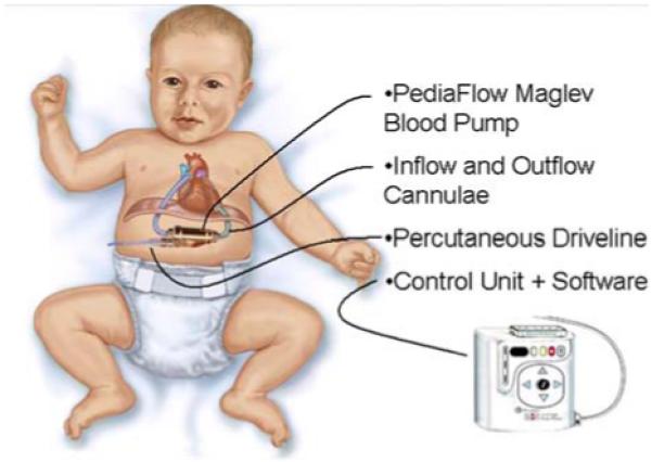
The PediaFlow ventricular assist system is comprised of an implanted blood pump (PF3), attached to the circulatory system through two blood conduits (cannula), and electrically connected to an external controller unit through a percutaneous drive line (see Fig. 1).
FIGURE 1. PediaFlow™ ventricular assist system, comprised of implanted blood pump, cannulae, connected to external controller by percutaneous driveline.
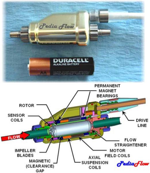
The PF3, the focus of this report, is a mixed-flow turbodynamic pump that propels blood by the rotation of a magnetically levitated impeller. Its size approximates that of an AA-battery (see Fig. 2). Magnetic suspension provides support to the rotor in five degrees of freedom. Radial, pitch, and yaw support are achieved by two sets of permanent magnet (PM) rings, referred to as “PM bearings,”54 located fore and aft. These magnets create instability along the axis of the rotor, which is countered by a feedback-controlled electromagnetic (voice) coil. This active system uses eddy-current sensors in the front and rear housings to detect the axial position of the rotor, and amplifiers within the external control unit to drive the voice-coil. The rotor is actuated by a 4-pole brushless DC motor, comprised of electromagnetic field coils in the chassis which couples to permanent magnets within the rotor. Thin titanium shells on the exterior of rotor and inner bore of the housing protect the magnetic components from exposure to blood, and vice versa.
FIGURE 2. The PediaFlow PF3 magnetically levitated mixed-flow blood pump, approximating the size of an AA-cell battery (top). Partial sectional view displays the principal subsystems (bottom).
METHODS
Design Philosophy
The development of a new ventricular assist device is an endeavor traditionally costing many millions of dollars. Consequently, the absence of an implantable pediatric VAD despite several decades of development of adult VADs can be attributed to economics.
Given the relatively small market size for these devices, it is difficult to recover large up-front investments with reasonable margins on sales. There is a need to limit risk of a protracted development process, and therefore a need for a highly efficient design process—one which does not rely solely on trial-and-error which has historically been a trait associated with this field.
Accordingly, the design philosophy of the Pedia-Flow group has been to adopt a prescriptive design algorithm: one in which begins with a meticulous breakdown of the design objectives, followed by a quantitative assessment of design options in terms of the desired engineering specifications.23 Succinctly, “form follows function.” The main components of this approach include (1) Generating an Objective Tree, (2) Conducting a Function-Means Analysis, (3) Mathematical Modeling, and (4) Optimization, described briefly in the following sections.
Objective Tree—“First Do No Harm”
According to the prescriptive design approach, it is essential to first clearly understand the definition of “success,” often called a utility function or design objective. This important step includes a characterization of the user requirements and constraints—both expressed and implied. Ideally, it should also consider the perspectives of all users and stakeholders: not just the surgeon and patient, but caregivers, family doctors, clinical technicians, nurses, third-party payers, etc. Accordingly this task was conducted by over 20 members of the PediaFlow team representing a variety of aspects of the product life cycle: from manufacturing through distribution and tracking.
A useful tool that assisted the team to navigate through this process, known as an Objective Tree, was used to distill detailed engineering specifications from high-level user requirements. It functions by successively breaking down the master objectives into sub-objectives. By progressing from “why to how,” the user requirements are translated into engineering objective functions. These functions can be eventually mapped to quantitative specifications that define the measurable goals of the design process and ultimate utility of the device. A portion of the objective tree for the PediaFlow is shown in Fig. 3. It indicates the top-level objectives: (1) Performance, (2) Biocompatibility, (3) Reliability, (4) Quality of Life, (5) Manufacturability/Cost, and (6) Development Risk. These were chosen collaboratively to represent the independent elements of Safety and Efficacy, which was the unanimously agreed-upon starting point. Each of these objectives was, in turn, broken down into a list of descriptive characteristics, which may be interpreted as subordinate objectives. An example is provided in Fig. 4 for the high-level objective Biocompatibility, given a relative weight of 40% and further refined into eight components. Again, these were mutually accepted as independent and completely defining the higher level objective. The Objective Tree exercise was performed at two stages in the development process: at the very start of the project before an initial configuration for the pump was determined, and again to discriminate between specific embodiments of a preferred topology.
FIGURE 3. Portion of objective tree used for evaluating design options.

FIGURE 4. Breakdown of weighted objectives for comparison of design options.

Pump Topology
There have been a myriad of blood pump designs proposed over the past 50 years, roughly falling into two categories: positive displacement pumps which mimic the function of the natural heart, and turbodynamic (also known as “rotary”) pumps which propel blood through the use of a rotating impeller. The choice to develop the PediaFlow as a turbodynamic pump was one not explicitly grounded in quantitative analysis, but based on extensive experience of the design team. The advantages were found to be plainly evident: minimal moving parts (one); absence of valves and flexing diaphragms; silent operation; not requiring a vent to atmosphere or compliance chamber; not limited by stroke volume; and others. For the same reason, the team was also predisposed to the use of magnetic bearings, as opposed to hydrodynamic or contact bearings. According to members of the team who have had favorable experience with magnetically levitated pumps, the reduction of shear stress, Coulomb heat generation, and avoidance of seals or purge system outweighed the cost of added complexity.2,11,12,21,40,44
Within the category of turbodynamic pumps, there are numerous configurations or topologies, even more with the added complexity of magnetic levitation. The choice of topology is a critical one, for it will define the trajectory of the ensuing development process—which might extend for several years.
The most dominant feature of a turbodynamic pump is the shape of the impeller, and consequently the route by which fluid is accelerated. On one extreme are the purely-axial pumps which operate much like a fan, adding energy by deflecting the flow in the circumferential direction. Purely centrifugal pumps are characterized typically by disk-shaped impellers with fluid entering at the center “eye” of the impeller and exiting at the outer periphery. Energy is added by a combination of centrifugal force and circumferential velocity. Between these extremes, there is a virtually infinite continuum of “mixed flow” pumps, also known as “diagonal” pumps.66 Depending on the type of impeller, there are a variety of stators and/or volutes that may be added to the flow path to recover kinetic energy imparted by the impeller.
For each choice of flow path, there are numerous configurations of magnetic elements that may provide the necessary suspension and actuation of the rotor. To consider a wide range of possible configurations, a shape grammar was utilized. This design tool permitted rapid evaluation of topologies by generating a family of pump layouts using the principal elements: (a) pump impeller blades, (b) pump stator blades, (c) motor permanent magnets, (d) motor windings, (e) active thrust coil(s), (f) axial thrust permanent magnets, (g) radial permanent magnets, and (h) structural elements (see Fig. 5). A total of approximately 20 configurations were initially considered. These were reduced to three based on a set of heuristic precepts, summarized in Table 1, which aims to provide a streamlined flow path and robust suspension, while limiting the complexity of the overall system. These final three topologies were then subjected to first-order engineering analysis and presented to the entire design team for comparison.
FIGURE 5. Examples of shape grammar used to evaluate topological configurations of electromagnetic and fluidic elements. RPM, radial permanent magnet; MW, motor winding; MPM, motor permanent magnet; ATC, active thrust coil; ATPM, active thrust permanent magnet; PI, pump impeller; FS, flow straightener; and SH, stationary hub. Solid line indicates mechanical coupling, dashed line indicates magnetic coupling. (a) A conical bearing configuration, (b) the Streamliner™ hemoglide configuration, (c) the Levacor™ system, and (d) the preferred PediaFlow topology.
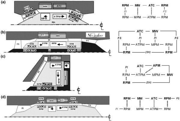
TABLE 1. Heuristic design precepts.
| Suspension |
| Efficiently use space (avoid “wasted” space) |
| Restrict magnetics to outer diameter |
| Avoid excessively large magnetic gaps |
| Avoid magnetics within spindle |
| Avoid microscopically small magnets and coil |
| Maximize surface area of magnetic gaps |
| Favor motor efficiency over voice coil for efficiency |
| Maintain motor components at the outermost diameter |
| Combined use of magnets |
| Flow path |
| Provide streamlined, uninterrupted main flow path |
| Minimize shear exposure |
| Avoid small clearances and |
| Limit surface velocity |
| Maintain small clearances at minor diameter |
| Avoid flow stagnation |
| Assure all surfaces are “washed” |
| Avoid extended (and repetitive) exposure to artificial surfaces |
| Avoid journals if possible |
| Avoid retrograde flow if possible |
| Minimize surface area |
| System |
| Maintain overall size within anatomic constraints |
| Use space to serve dual functions |
| Avoid central spindle |
| Minimize seams and redundant mating surfaces |
| Minimize number of magnetic components |
Weighting and Ranking the Objectives
While high-level design decisions rely heavily on experience, heuristics, and “creativity,” the detailed designs, or features, may be compared quantitatively. This is facilitated by the use of weighted objectives analysis (WOA), a two-step process. The first step entails quantitatively apportioning weights {wi, 0.0–1.0} to each of the individual components of each high-level objective based on their relative importance. This is performed progressively, analogous to the objective tree, until each specification has received a weight based on an absolute scale. The sum of all the weights, wi, are then equal to 1.0
| (1) |
where N is the total number of design criteria. This is also a collaborative procedure, performed interactively during a design review session of key investigators.
The second step of the procedure requires assignment of objective indices, or scores, to each of the design criteria of each embodiment or design alternative. Then the overall composite score for any particular embodiment is the weighted sum:
| (2) |
where represents the individual score for the ith criterion of the jth design alternative. Since the set of objective indices are comprised of a wide variety of dimensioned variables and subjective scores, they were first converted to a normalized scale of 0.0 (worst) to 1.0 (best). In the simplest cases, a linear monotonically decreasing scale was employed:
| (3) |
where ϕ is a dimensioned variable, ϕopt is the associated optimal value, receiving full merit of 1.0, and ϕM is the upper (maximum) limit, receiving zero merit. Above the upper limit, the function either assumes a negative value (penalty), or is clipped at zero, depending on the circumstance.
For many of the design variables in this study, it was more appropriate to assign a nonlinear mapping function between the dimensional value and the normalized score. For example, <efficiency> which ranges from 0 to 100%, cannot be simply scaled, since an efficiency of 0% is completely unacceptable, and an efficiency of 100% is not practically achievable. In such cases, one of two nonlinear scaling functions was used:
- A quadratic, unimodal, convex function:
where ϕopt is the extremum, receiving a score of 1.0 and ϕm is a lower bound corresponding to zero score, and the upper bound, ϕM = ϕm + ϕopt.(4) - An exponential function, providing a sharp constraint at ϕM:
(5)
In situations where quantitative metrics were impractical or unavailable, such as <orientation of inflow port>, a subjective scale was used, for example {excellent = 1.0, very good = 0.75, good = 0.5, fair = 0.25, bad = 0.0}. Finally, a confidence coefficient {ci, 0–100%}, was introduced to account for any uncertainty in the particular performance scores. These were chosen subjectively, based on the completeness of data upon which the score was derived. For example, a score based on definitive experimental data received 100% confidence, while those based on past experience or speculation received lesser confidence, as low as 10%. Therefore the overall objective for each of the design options was computed as:
| (6) |
and was presented graphically to the design team for approval, and ultimately selection of a single leading design for further development.
Multi-Disciplinary System-Level Optimization
It is evident from the topologies in Fig. 5, that electromagnetic and fluidic elements are closely integrated. For example, magnetic gaps are shared by fluid passages, wherein magnetic efficiency requires these dimensions to be small, while prevention of hemotrauma requires them to be large. There are in fact several critical design features that affect multiple subsystems, depicted in Fig. 6, and likewise require compromises among objectives. The pump, for example, comprised of the impeller and flow straighteners (if present) is characterized by a relationship between pressure, flow, and rotational speed. The motor, which is integrated into the pump rotor, shares the same speed; therefore the torque–speed–current relationship of the motor must be optimized to match the operating point (or range) of the pump—to optimize the overall efficiency, hence power consumption.
FIGURE 6. Inter-relationships between subsystems illustrating key design parameters affecting multiple sub-systems. Design constraints and objective functions (italics) represent the fundamental variables involved in multi-disciplinary optimization.

The physical dimensions are likewise coupled: the outer diameter of the impeller dictates the diameter of the motor rotor, which indirectly affects the diameter of the flow passage, and ultimately the overall size of the devices. The efficiency of the motor is inversely related to the size of the magnetic gap between rotor and windings; since this gap is occupied by blood, its dimension also dictates the shear stress in the fluid annulus (clearance) interconnecting impeller and aft flow straightener. Since shear stress is inversely proportional to the gap dimension, hemolysis may become unacceptably high if the gap is made too small—depending on the speed of the rotor. The function of the passive magnetic bearings is also dependent upon the physical gap between the rotating and stationary ring, which is likewise occupied with blood. The radial stiffness of these bearings is optimized by minimizing the gap, thereby extending the stable range of operation, and optimizing shock load capacity. However the axial stiffness is directly related to radial stiffness, and must be overcome by the voice coil actuator. Excessive stiffness would require unacceptably high electrical current to launch the magnetic suspension. An additional consequence of stiffness is the axial travel of the rotor, which in turn is related to the nominal clearance between the tips of the impeller blades, and the cowl.
The tip clearance is an especially critical element of hemocompatibility.4,41,77 The use of virtually-zero-power (VZP) feedback control for the voice coil causes the rotor to migrate against the pressure gradient2; therefore pulsations of pressure caused by the native heart will cause the tip clearance to likewise vary throughout the cardiac cycle. This in turn will alter the fluid dynamic shear caused by the blade tips, which could become excessive unless the magnetic suspension is appropriately stiff. The permissible limits of the tip clearance are dependent upon the height of the impeller blade, which in turn affects the diameter of impeller, hence the speed of the rotor, efficiency of the motor, and so on, ad infinitum.
A multi-disciplinary mathematical approach was implemented to reconcile these competing demands for performance, hemocompatibility, space, complexity, etc. A methodology, developed in prior Levacor™ VAD11 and Streamliner™ VAD2 programs, entails the use of multiple reduced-order algebraic models for the fluid path(s), motor, suspension, rotordynamics, and heat transfer. These equations were implemented using Microsoft Excel® and MathCAD (PTC, Needham, MA, USA).
Mean line fluid analysis was used to predict pump performance, derived from standard theory of turbodynamics66 coupled with empirical formulae specifically relevant to miniature blood pumps.63 Pump efficiency, rotor speed, and rotor torque were computed as a function of flow, pressure head, and the physical dimensions of the pump features. The electromagnetics and rotordynamics relied upon closed form solutions for the forces and stiffnesses between electromagnetic components, described previously.21,54 Briefly, the technique is based on replacing each magnet in the structure with a pair of hypothetical current sheets that create an equivalent magnetic field. This permits the computation of force and stiffness arising from the interaction of any two current sheets by superposition. The magnetic force per unit length of the current sheet interaction is then:
| (7) |
where μ0 is the permeability of free space, Hc, H’c coercivity of the magnets, Δr is the radial separation between faces, Wz and W’z are the widths of the two magnets, z is the axial coordinate, Δz is the axial separation between the two magnets, and R is the distance between the centers of the two sheets. Then the sum of the interactions for all the equivalent current sheets in the rotor and stator is computed to determine the magnetic bearing force and stiffness. The net force from one magnet array acting on another magnet ensemble is calculated as the sum of the forces of all their representative current sheets. The expression can also be differentiated with respect Δz to obtain the axial stiffness, and the radial stiffness may be obtained by application of Earnshaw’s theorem.25 Similar analytical models were developed for the toroidally wound motor that rotates the impeller and for the voice coil actuator that provides axial (thrust) suspension to the rotor.
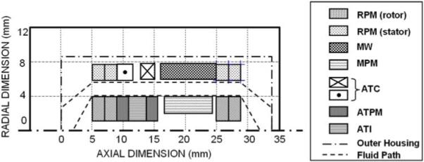
Although there were over 100 independent design parameters for the design configurations considered in this study (25 associated with the pump, and 80 with the electromagnetics), the relative simplicity of reduced-order models allowed rapid iterative solutions to be computed, hence numerically optimized for numerous design scenarios. The cost functions for these computations were derived from the design objectives summarized in Table 2. Electromagnetic components were optimized using a nonlinear conjugate gradient solver available in MathCAD software (PTC, Needham, MA, USA); and the corresponding pump equations were solved in Microsoft Excel® using the embedded Generalized Reduced Gradient (GRG2) nonlinear optimization code (Frontline Systems, Inc., Incline Village, NV, USA). The coupling there between, represented in Fig. 6, was performed manually by imposing constraints from the result of one optimization upon the associated optimization of the coupled counterpart. Additional external constraints were also imposed to provide bounds on the variables such that they remain nonnegative and do not increase without limit. The output of the optimization was displayed both in tabular format and schematically (see Fig. 7). This provided a “reality check” of the results, as well as a means to rapidly evaluate the effect of compromises among the constraints or weights of the objective functions. For example, a small reduction in required efficiency of the motor from 95 to 90% can have a dramatic effect on its size. Several sensitivity analyses of this type were performed to re-assess the design specifications which had been previously prescribed presumptively.
TABLE 2. Metrics of design objectives.
| Anatomic |
| Max. diameter |
| Max. length |
| Inlet/outlet direction (wrt outlet graft) |
| Shape/form factor - wrt fit and erosion |
| Weight/mass |
| Implantability in newborn pts |
| Performance |
| H-Q slope |
| Overall efficiency (BEP) |
| Overall efficiency (off-design) |
| Disk-friction (windage) losses |
| Volumetric losses (leakage) |
| Motor efficiency (BEP) |
| Motor efficiency (off-design) |
| Volute/stator losses |
| Axial thrust |
| Radial imbalance |
| Biocompatibility |
| Normalized index of hemolysis |
| Stability at low flow |
| Inherent recirculating or retrograde flow |
| Blood wetted surface area |
| Number of blind crevices |
| Number of seams |
| Max. temperature rise of blood surfaces |
| Max. temperature rise of tissue surfaces |
| Reliability |
| First critical speed margin |
| Shock tolerance |
| Performance of touchdown bearings (est.) |
| Required sensor accuracy |
| Small magnetic gaps |
| Manufacturability |
| Number of components |
| Number of seams/welds |
| Machining complexity |
| Min. tolerance requirement |
| Avoid infinitesmally thin shells |
| Tolerance stack-up |
| Max. acceptable radial run out |
| Max. acceptable axial offset |
| Ability to dynamically balance |
| Gap shared by fluid and magnetics (y/n) |
FIGURE 7. Output of lumped-parameter optimization of the electromagnetic elements of the pump. ATI, active thrust iron; RPM, MW, MPM, ATC, and ATPM defined in Fig. 5.
CFD Analysis and Optimization
The semi-empirical relationships used in mean line analysis of the pump involved numerous assumptions and failed to account for small, although important, details such as the thickness of the blades and associated radii of the impeller tip and root, wrap angle of the impeller blade, angle of the trailing edge, and several others. Therefore computational fluid dynamics was used to both calibrate the mean line formulae, and to optimize the unspecified features of the blood flow path. The procedure, described previously18,19,74-76 utilized a commercial CFD program (CFX 11, ANSYS, Inc., Canonsburg, PA, USA) employing both k–ε and SST turbulent models, that is coupled to an external optimization algorithm (see Fig. 8). Briefly, an initial geometry is programed based on the design parameters derived from mean line analysis, which are supplemented by initial guesses for the remaining detail parameters mentioned above. CFD simulation is performed to predict the internal velocity and pressure fields, from which shear stress is computed along with the derived objective functions. The latter are comprised of a sub-set of metrics precipitating from the objective tree analysis, described previously, and primarily relate to efficiency, hemolysis, and thrombogenicity. Efficiency was computed directly from the ratio of hemodynamic power (pressure × flow) to shaft power (torque × speed). Potential trauma to blood cells (hemolysis) was computed using an Eulerian hemolysis model, introduced by Garon and Farinas,30 based on the empirical model of Giersiepen et al.31
| (8) |
where τ(x, t) is a scalar norm of the shear exposure history recommended by Bludszuweit,15 v(x, t) is the velocity field, D is the normalized fraction of hemoglobin (Hb) released into the plasma (from 0 to 1), DI is a linearized damage variable that is integrable along a streamline, and σ is the damage production rate per unit time. The advantage of this method, as compared to a Lagrangian method, is that it is rapidly computed, covers the entire flow domain, and can better predict the transient stresses.
FIGURE 8. CFD simulation and optimization algorithm.
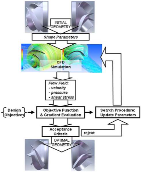
A definitive numerical index that defines thrombosis potential does not currently exist, therefore the flow field was also evaluated qualitatively for evidence of stagnant, recirculating, or disturbed flow—known from prior experience to be associated with deposition of blood elements.
CFD simulations were performed iteratively in which the free variables were altered until a satisfactory compromise between efficiency and HI was achieved, and the flow field was absent of recirculation or stagnation.
Finite Element Simulation
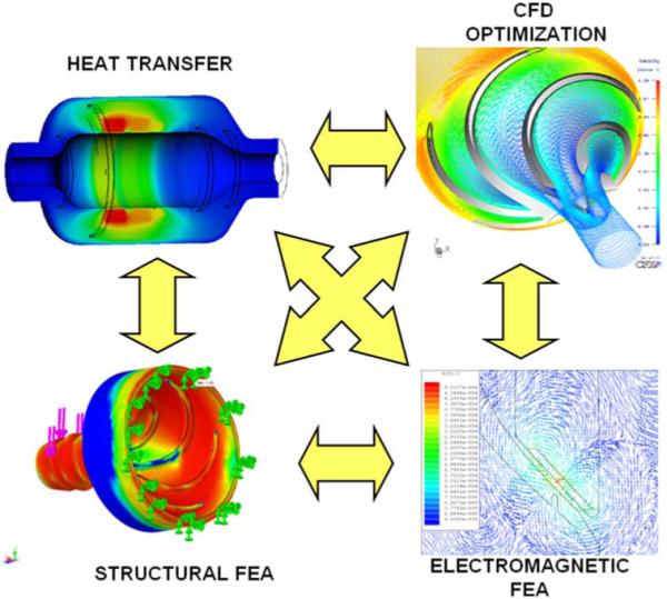
In addition to CFD, numerical simulations were also performed for the electromagnetic and structural components and assemblies. Finite element analysis was conducted using commercial software (ANSYS, Canonsburg, PA, USA) to calibrate and validate the closed-form solutions used in system-level optimization. These simulations effectively provided more accurate approximations of the empirical coefficients, which in turn are affected by secondary variables, such as shape, edge effects, inter-component coupling, etc. Analogous to the reduced-order analyses, varying degrees of coupling was involved between numerical simulations, requiring their shared variables to be reconciled—either sequentially, or collaboratively through the imposition of constraints (see Fig. 9).
FIGURE 9. Numerical analysis and optimization of fluid dynamics, electromagnetics, heat transfer, and structural stresses.
Experimental Verification and Validation
The computationally-intensive design approach described above is intended to reduce the need for expensive and time-consuming experimental design iterations. Nevertheless, imperfections in these mathematical models introduce risk of costly mistakes propagating downstream in the development process. To manage these risks, experiments were conducted on the key sub-systems of the device, namely the motor, magnetic suspension, sensor, and pump. Bench-top studies with prototypes of these assemblies were performed throughout the course of development, and were used to validate and calibrate the mathematical models. For example, flow visualization studies were performed with a transparent, shaft-driven replica of the impeller to corroborate numerical predictions of efficiency, pressure distribution, and streamlines.62
Following fabrication of a complete prototype pump, additional bench-top studies were performed with blood, and a blood analog solution, to confirm hemodynamic performance and sufficiently low hemolysis, thereby permitting in vivo studies to be performed. One such study was performed with the final prototype PediaFlow pump, PF3. The prototype was implanted a healthy lamb in accordance with the Institutional Animal Care and Use Committee guidelines at the University of Pittsburgh. The pump was introduced into the circulation as a left ventricular assist device, interposed between the left ventricle and descending thoracic aorta. The surgical procedure involved inserting a modified wire-reinforced polyurethane cannula (18fr, DLP, Medtronic, Minneapolis, MN, USA) into the apex of the left ventricle through a stab incision and secured with a sewing ring fashioned from thick surgical felt (PTFE, C.R. Bard, Murray Hill, NJ, USA). The outflow from the PF3 was 6 mm diameter polyester vascular graft (Vascutek, Terumo, Inc.) anastomosed to the descending thoracic aorta. The pump was operated at a fixed speed of 14500 RPM. The flow rate was measured via an ultrasonic transit-time flow probe (Transonic, Inc., Ithaca, NY, USA) attached to the outflow graft. Throughout the study, pump flow, power consumption, and carotid blood pressure were recorded. Hemorheology and serum chemistry values were collected regularly to assess the biological impact of the pump on blood damage and organ function.
RESULTS
Topology
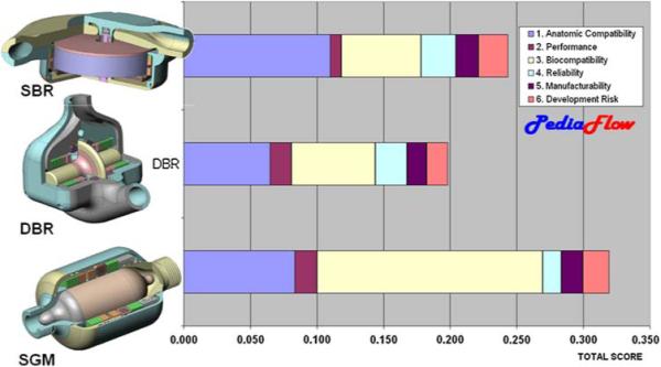
The conclusion of the topological exercise resulted in three leading design configurations incorporating a variety of magnetic suspension, motor, and fluid path arrangements. All of the selected topologies utilized permanent magnet radial and moment bearings, an active axial thrust bearing, and a brushless DC motor. The three topologies were distinguished by their fluid paths: a Symmetric, Dual-Bladed Radial (DBR) configuration; an asymmetric, Single-Bladed Radial (SBR) configuration; and a Single Gap Mixed-Flow pump (SGM) (see Fig. 10). Initial reduced-order analyses of these three options were combined with subjective assessments by the design team to formulate weighted objective scores. The candidate design received relatively even scores for reliability, manufacturability, and development risk. The distinguishing metrics were anatomic compatibility in which the SBR design was favored due to its discoid shape; and biocompatibility in which the SGM was favored, predominantly due to its single antegrade flow path, absent of any small journals or recirculating flow passages. The reliability score of this design was slightly penalized due to the large magnetic gaps that it requires, which would adversely affect rotordynamics stability. Nevertheless, the SGM was the clear “winner” and ultimately received unanimous approval of the team.
FIGURE 10. Weighted objective comparison of three leading design options.
The fluid dynamic and electromagnetic suspension subsystems of the SGM design was subjected to reduced-order analysis as described in the Methods. Due to the disparity of software platforms, the optimization of the subsystems were initially performed sequentially, whereby the rotor speed and torque were first computed by the pump formulae (in Excel), based on an initial guess for the rotor diameter, and transmitted as constraints to the electromagnetic program (in MathCAD) for optimization of multiple cost functions. As experience was accumulated through subsequent iterations, the process became less sequential and more contemporaneous, approaching a collaborative optimization approach. Nevertheless, the process was not completely autonomous but required at least two manual steps in each iteration. This was found necessary due to the relatively large number of free parameters which gave rise to many local minima within the parameter space. Therefore the initial starting guess for the parameters was critically important for finding reasonable solutions. These initial values were based on intuitive estimates of approximate sizes of components gleaned from previous designs and engineering experience gained from those designs.
Final Detailed Design of PediaFlow™ PF3
Three generations of PediaFlow prototypes were fabricated and tested in vivo, all based on the same topology and differing primarily in the sizing of components. The third and final design, PediaFlow PF3, is shown in Fig. 2. The prototype, fabricated primarily from Ti6Al4V alloy, NdFeB magnets, iron, copper, provides detachable barbs at both ends for connections to an inflow cannula and outflow graft. The magnetic components are encased in a two-part housing: a cover and an end body. These components are shaped asymmetrically to conserve volume while providing space for routing and terminating the conductors from a cable feed-through assembly on the housing end body near the cannula outflow adapter. The single streamlined annular flow path includes a mixed-flow (diagonal) impeller integrated with a principally cylindrical rotor (8 mm diameter) within a cylindrical bore (11 mm diameter) having a conical diffuser and collector at the fore and aft ends respectively. Flow straighteners (stay vanes) are machined on the interior bore of the aft housing that cooperate with the conical tail of the rotor to recover pressure from the dynamic head induced by the circumferential velocity of the blood exiting the impeller.
The PF3 represents a size reduction of approximately 53% from its predecessors,38 and closely approximates the size of a AA size battery. This dramatic reduction in size was a result of a change in one of the fundamental rotordynamic assumptions that was made early in the development program. It was originally assumed that rotational speed should avoid the natural resonances of the system, and therefore a constraint was imposed that maintained a critical speed margin to provide a sufficient factor of safety. However, by relaxing this constraint, it became possible to maintain stable rotordynamics above the critical speeds. This scenario permitted much greater range of rotor speed, which in turn reduced the stiffness requirements of the magnetic bearings, and allowed a smaller lower-torque high-speed motor to be used.
An additional benefit of super-critical design is the relatively large gap in the annular region (approximately 1.5 mm) of the flow path, which maintains shear stress below an acceptable level (<50 Pa at nominal pressure and flow). This is an important distinguishing feature of the PF3 design that obviates any secondary or tertiary flow paths common in previous turbodynamic blood pumps. Additional specifications of the final PF3 pump are provided in Table 3.
TABLE 3. Physical characteristics of PF3.
| Total displaced volume | 16.6 cc |
| Total mass (w/o conductors) | 50 g |
| Blood-wetted surface area | 25.8 cm2 |
| Priming volume | 2.0 cc |
| Total no. of magnets | 45 |
| Impeller speed | 18000 RPM |
| Nominal flow rate | 1.0 lpm (at 90 mmHg) |
| Normalized index of hemolysis | 0.047 |
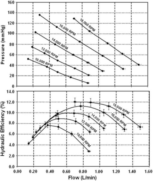
In vitro bench top experiments with the PF3 prototype performed with a blood-analog solution of water and glycerol confirmed acceptable hemodynamic performance (see Fig. 11). At an operating speed of 18000 RPM, the pump was able to produce a nominal flow rate of 1.2 lpm against a pressure head of 75 mmHg, which corresponds to the hemodynamic requirements of a healthy 8 kg infant (based on a cardiac index of 3.0 L/min/m269 and 50th percentile mean blood pressure.47 Subsequent experiment with ovine blood also demonstrated an acceptably low level of hemolysis, computed in terms of normalized index of hemolysis, NIH = 0.0467, defined previously.48 The corresponding hydrodynamic efficiency is slightly greater than 10%, which combined with a motor efficiency of 85%, translates to an electrical power requirement of 1.8 W.
FIGURE 11. Hemodynamic performance of PediaFlow PF3.
In Vivo Experiments
The initial in vivo validation study of the PF3 was conducted for 72 days, and was terminated electively with no complications (Fig. 12). The average serum chemistry and hematology measurements were indistinguishable from pre-operative baseline values, indicating normal organ function (see Table 4). Hemolysis, as evidenced by plasma free hemoglobin (9.2 ± 2.2 mg/dL) was also close to baselines levels at all points throughout the study (Table 4).
FIGURE 12. Implantation of PediaFlow PF3 in ovine prior to 72-day in vivo study (top). Lateral X-ray, post-operative day 2 (bottom).
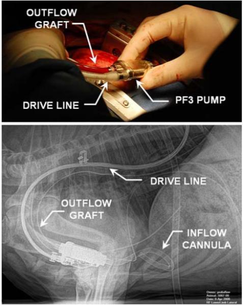
TABLE 4.
Serum chemistry and hematology for 72 day in vivo study (pre-operative baseline values in parenthesis)
| Mean ± SD (baseline) |
Reference ranges |
|
|---|---|---|
| WBC (×1000/mm3) | 7.3 ± 1.2 (7.2) | 4–12 |
| RBC (×106/mm3) | 7.6 ± 0.5 (10.3) | 9–15 |
| Hgb (gm/dL) | 8 ± 0.9 (9.9) | 9–15 |
| HCT (%) | 23.3 ± 2.7 (26.5) | 27–45 |
| Platelets (×1000/mm3) | 626 ± 248 (2000) | 250–750 |
| MCV (μm3) | 29.7 ± 1.8 (26) | 28–40 |
| MCH (pg) | 10.3 ± 0.6 (9.6) | 8–12 |
| MCHC (%) | 34.9 ± 1.2 (37.4) | 31–34 |
| Neutrophils (×1000/mm3) | 3 ± 1.3 (1.7) | 0.7–6.0 |
| Lymphocytes (×1000/mm3) | 3.7 ± 1.5 (4.6) | 2–9 |
| PT (s) | 22.1 ± 6.2 (26.6) | N/A |
| INR | 2.2 ± 3.5 (2.3) | N/A |
| PTT (s) | 61.2 ± 22.7 (29.7) | N/A |
| Fibrinogen (mg/dL) | 233 ± 90 (200) | 100–500 |
| plfHb (mg/dL) | 9.2 ± 2.2 (16.8) | <50 |
| BUN (mg/dL) | 21 ± 15.3 (16) | 10.3–26 |
| Glucose (mg/dL) | 91.9 ± 15.1 (88) | 44–81.2 |
| Creatinine (mg/dL) | 1.4 ± 1.5 (0.8) | 0.9–2.0 |
| Ca (mg/dL) | 10 ± 0.9 (10.5) | 9.3–11.7 |
| Mg (mEQ/L) | 1.1 ± 0.2 (1.6) | 2.0–2.7 |
| Cl (mmol/L) | 111 ± 4.7 (105) | 100.8–113.0 |
| K (mmol/L) | 6.1 ± 1.6 (4.4) | 4.3–6.3 |
| Na (mmol/L) | 143 ± 4 (144) | 141.6–159.6 |
| SGPT(ALT) (IU/L) | 11 ± 9 (13) | 14.8–43.8 |
| SGOT(AST) (IU/L) | 76 ± 46 (71) | 49.0–123.0 |
| Albumin (g/dL) | 2.7 ± 0.6 (3) | 2.4–3.0 |
| Tot. bilirubin (mg/dL) | 0.1 ± 0 (0.2) | 0.1–0.5 |
| GGT (IU/L) | 44 ± 13 (57) | 10–118 |
| LDH (IU/L) | 437 ± 146 (325) | 238–560 |
| Phos (mg/dL) | 8.1 ± 1 (7.5) | 4.0–7.3 |
| Cholesterol (mg/dL) | 71.1 ± 26 (40) | 44.1–90.1 |
| ALP (IU/L) | 82.7 ± 23.6 (139) | 26.9–156.1 |
| CPK (IU/L) | 500 ± 1181 (111) | 47–4212 |
| Tot. protein (g/dL) | 5.9 ± 0.2 (6.2) | 5.9–7.8 |
Gross postmortem examination revealed a well encapsulated pump and inflow and outflow tubing with all components intact. No adverse reactions were found to the cannula position in the ventricle or evidence of thrombotic embolism in the lungs, liver, or spleen. A minor cortical infarction was noted on the left kidney that appeared to be old and well-healed, suggesting that it originated at the time of implantation. Further examination of the disassembled pump and its components revealed clean surfaces on the housing and impeller with no evidence of thrombus or scratches that could cause embolic complications. Overall, the first in vivo study was viewed to have achieved all of the intended positive outcomes.
DISCUSSION
The emphasis of this report was intentionally placed upon the design approach as contrasted with the features of resulting product. This reflects the fact that the tools and algorithms used for designing new ventricular assist devices continue to evolve as new technologies are brought online and new products are introduced. This is a necessary evolution to meet the modern demands for rapid, cost effective introduction of innovative cardiovascular devices.
Evolution Toward Simulation-Based, Prescriptive Design
The era of trial-and-error that persisted during the five decades since the implantation of the first total artificial heart in humans in 1957 and the current millennium is giving way to a new period of simulation-based design. The recognition of this transformation by the community is evidenced by the recent inauguration of a joint workshop in June of 2008 by the FDA, NHLBI and NSF titled Computer Methods for Cardiovascular Devices.28 Indeed the birth this very journal represents a growing need for dialog among scientists, engineers, and physicians on the theories and methodologies driving the development of cardiovascular devices.
Remarkable progress has been made toward introducing cardiac assist devices into the mainstream of cardiac therapy. Nevertheless, clinical practice has yet to achieve the tens to hundreds of thousands of cases anticipated by the 1982 Office of Technology Assessment report.45 Many will agree that the deficit is largely due to the shortcomings of the technology itself. Yet the imperfections of the technology are clearly not due to lack of effort, but the very difficulty of the challenge. And the difficulty has consistently been underestimated.
Further evidence of the immaturity of the field of blood pump design is the wide diversity of devices that have been developed, or proposed, for this single application. The choice of a pump for most commercial applications is dictated by relatively unambiguous rules. However, there has yet to be a consensus on the optimal design of a pump destined to replace or augment the function of the heart.29,36,63 It is also intriguing that the first three decades of artificial heart and VAD development focused almost exclusively on pulsatile, positive displacement devices, almost to the exclusion of turbodynamic (“rotary”) pumps. The first recorded suggestion of such a device was made in 1960 by Saxton and Andrews61; however, it was not until 1990 that ardent development of turbodynamic blood pumps for chronic use was undertaken.3,20,51,60 Ironically, developers of pneumatic blood pumps had envisioned the use of turbodynamic pumps to pressurize hydraulic fluid to supplant compressed air.32 Following the success of Wampler’s catheter-deployed Hemopump,72 a geometric growth in rotary blood pump development was observed. Today, turbodynamic pumps are regarded by many as “second generation” and even “third generation” technology. Considering the venerable history of turbodynamic technology, dating back to Archimedes (ca 287–212 BC), one might question why this family of blood pumps was not considered from the outset.
A valid explanation relates to the differences between the prescriptive and descriptive approaches to design.23 The latter is a generally heuristic process that draws from years of trial and error leading to fundamental design precepts that help generate solution concepts early; and applying known solutions to related problems. For example, the germinal notion to replace one positive displacement pump (the heart) with another (pneumatic) is an intuitive starting point. In this particular case, the ensuing 30 years of development of artificial hearts and VADs along this path, ultimately transitioning to turbodynamic blood pumps, may be viewed as a very long trial-and-error process.
Creativity, therefore, introduces risk of the unknown. When time and resources are limited, as is the case of pediatric pump development, the risks of attempting something radically different from the norm might outweigh the potential benefits. The management of this risk is precisely the role of engineering models, and the prescriptive design approach. It is an algorithmic method, which begins with carefully characterizing the design objectives, and translating from function to form in an analytical fashion. It is closely related to the well-known waterfall model, which is a central component of the design guidance documents provided by the FDA.27
Referring back to the Weighted Objectives exercise depicted in Figs. 3 and 4, it was implied that an optimal solution may be identified if (a) there exists a rich set of prospective designs to choose from, (b) there is a clear mapping between user requirements and engineering specifications, and (c) the performance (and biocompatibility) data of each alternative are available. Historically, the means of generating ideas was through intuition, experience, and perhaps mimicry of nature; and the means of obtaining performance data was through sequential prototype testing: in vitro, in vivo, and clinically. The consequence is to proceed through the development process, and even to clinical trials, with great uncertainty, yet hopeful that the assumptions made earlier were correct; or at least caught early enough to allow another iteration before time and funding are exhausted.
In the case of the PediaFlow, considering the large quantity of free parameters represented in Figs. 2, 7, 8, and 9, and sparseness of formalized guidance for prescribing these details, the odds are stacked against getting it right on the first pass. A modern engineer would never contemplate constructing an aircraft in this manner; yet, the early years of aviation was replete with failed attempts at flight until the self-taught Wright Brothers invoked principles of prescriptive design. Today’s airliners are designed almost entirely on a computer before testing.26
The development of modern design tools to facilitate prescriptive design is an ongoing activity within engineering design research. Finite element simulations, for example, have been employed for decades in the aerospace and automotive industries; however, their entry into the medical device industry has lagged considerably. Likewise, conceptual design tools such as design agents and shape grammars have found a valuable role in many industries1,52,53 but have yet to be adopted for cardiovascular applications.
The simulation models used in the PediaFlow development allowed the designers to explore “what if” scenarios with minimal penalty of time and resources. In particular, the transition to supercritical operation would never have been pursued based on speculation alone. An added advantage of mathematical simulations that was exploited in the PediaFlow development was the use of numerical optimization. The details of such algorithms have been described elsewhere.3,17,18,33,54 Particularly, the use of reduced-order and closed-form models permitted rapid exploration of over 100 variables—far beyond the capabilities of a human designer.
Limitations of Mathematical Models
Engineering models, by definition, are not exact. They are abstractions and approximations of real world systems. Model results can provide rich details of great apparent precision. They can thereby seem incontrovertible when they may in fact be fraught with uncertainty. However, the resemblance to reality is limited by the accuracy of the underlying assumptions and approximations. To quote Henry Petrosky, “The computer is both a blessing and a curse for it makes possible calculations once beyond the reach of human endurance while at the same time also making them virtually beyond the hope of human verification…58” It is therefore vital to be wary of the limitations of computational results, and to seek measures to mitigate risks through calibration and cross-validation with alternative approaches.
In the context of cardiovascular device design, this limitation is particularly acute when attempting to predict blood trauma and thrombosis. The current project employed a semi-empirical model for hemolysis described by Garon and Farinas,30 with origins dating to the early 1970’s,59 in turn referring to observations by Blackshear et al. in the late 1960s.14 Although such models of hemolysis have been extensively developed over the past decades6,13,15,31,35,43,78 they universally treat blood as a single continuum, like water or oil, and do not account for its cellular composition. Such models have found many practical applications; however when the dimensional scales approach that of an individual cell or ten’s of cells, the continuum assumption becomes less reliable. For example, it has been shown experimentally that the trajectory of individual cells flowing within small channels and across the tip of an impeller blade may not follow the streamlines of the plasma.4,79,80 Consequently, the history of shear exposure of any individual cell passing through a ventricular assist device may vary greatly from the pathlines computed by a homogenized model. This thwarts the development of a universally predictive model for general situations; therefore, investigators continue to seek more unified hemolysis models to supplant those of the early 1970s.7,34,57
The greatest and most vexing engineering challenge, by far, is the elimination of unwanted thrombosis. Because of the complexity of the fluid dynamic interactions and biochemistry of the coagulation cascade, the prospect of developing an accurate, predictive model of this phenomenon has been elusive. Accordingly, mathematical models for simulating platelet activation, protein adsorption, and thrombus deposition in cardiovascular devices are still in their infancy.8,37,39,56,64,65,73 The hemodynamic modeling within the PediaFlow program has therefore relied upon surrogate indicators of thrombogenic potential, such as stagnant flow, recirculation zones, and other forms of disturbed flow. Pragmatically, the risk of thrombosis is reduced by the use of appropriate biomaterials and coatings; avoidance of surface irregularities and crevices; and ultimately the use of some form of anticoagulation.
Clearly, this current state of affairs demonstrates that there remains room for improvement of both the engineering models, and the devices themselves. While the benefits can be great, there is a nonnegligible cost associated with both developing accurate models and implementing them. Accordingly, computational-based design is still dependent upon experimental verification and validation, and there remain many circumstances where experimentation on physical prototypes, although costly, is much more expedient.
Ongoing and Future Work
Although the PediaFlow PF3 has reached a significant milestone, a great deal of work remains to both perfect the pump and to prepare the peripheral components for clinical use. Improvements to the PF3 pump will aim to expand its upper range of operation, and to accommodate pulsating and reverse flow. However, the blood pump itself is a fraction of overall engineering effort involved in bringing a pediatric circulatory system to market. Ongoing and future work therefore will focus on “all the other stuff,”1 such as the cannulae, power cables, and connectors, the control consoles, communication links, power systems, sterilization, packaging, etc. There has been far less written about the detailed design of these peripherals, however they are subject to the same rigorous requirements as the pump itself; for the chain is only as strong as its weakest link.
Despite the best efforts to optimize hardware and mitigate risks, the ultimate test of efficacy and safety of the PediaFlow system must rely on clinical testing. These clinical outcomes will reflect all the technical decisions made along the development path, including the initial choice to pursue a turbodynamic pump design—as opposed to a positive-displacement pump. This choice was based on several factors, but discounted the physiological importance of hemodynamic pulsatility. This has been a topic of intense research for several decades,24 and prompted extended scientific debate throughout the 1990s on the potential sequella of diminished pulsatility: hypertension, lymphatic stasis, end-organ hypoperfusion, impairment of baroreflex, and others.9,42,49,50,67,70 The positive clinical experience reported in recent years16,55 has allayed some of this trepidation. Nevertheless the remaining uncertainty of long-term effects motivate continued study, particularly in the pediatric population for which there is far less clinical experience.71
CONCLUSIONS
This report described a prescriptive, multi-disciplinary, collaborative approach to develop, de novo, a miniature turbodynamic blood pump specifically for infants and toddlers with congenital and acquired heart diseases. The result is believed to be the world’s smallest maglev blood pump. The use of engineering models and numerical optimization has hastened the progress of this project, and demonstrated the value of a prescriptive design approach. However, the demand for perfection, and the penalty for failure, are exceedingly high. And the complexity, uncertainty, and imperfection of physiological models cannot completely eliminate some degree of empiricism and trial- and-error.
Although “absolute certainty about the fail-proofness of a design can never be attained, for we can never be certain that we have been exhaustive in asking questions about its future,58” it is hoped that the perpetual advances in biomedical engineering and adoption of modern engineering practices will continue to increase the functionality, reliability, and biocompatibility of these devices. Though it is unlikely that mechanical blood pumps will ever approach the exquisite perfection of the native heart, future improvements will be increasingly dependent upon refinement of engineering tools with which to design them, and effective communication between medical and engineering disciplines.
ACKNOWLEDGMENTS
The author is grateful for the contribution of the many members of the PediaFlow consortium, past and present including: Dorian Arnold, Tim Bachman, Gill Bearnson PhD, Shawn Bengston, Amanda Daly, Chenguang Diao PhD, Arielle Drummond PhD, Jeff Gardiner, Samuel Hund, Gordon Jacobs, Carl Johnson, Daniel Noh PhD, Bradley Keller MD PhD, Pratap Khanwilkar PhD, John Kirk, Robert Kormos MD, Peter Kouretas MD, Chung-Ming Li, James Long MD PhD, Tim Maher, Phillip J. Miller, Victor Morell MD, Salim Olia, Ed Prem, Fangjun Shu PhD, Trevor Snyder PhD, Stijn Vandenberghe PhD, William Wagner PhD, Steven Webber MBChB, Joshua Woolley, and Jingchun Wu, PhD; and former members of the StreamLiner design team including Greg Burgreen PhD, Zhongjun Wu PhD, J. Andrew Holmes, Bartley P. Griffith MD, and many other collaborators with whom he has worked and studied. We thank World Heart Inc. for their contributions to this program. We are also grateful to the National Institute of Health for financial support under Contract HHSN268200448192C (NO1-HV-48192), “Pediatric Circulatory Support,” and Grant R01 HL089456-01 “Multiscale Model of Thrombosis in Artificial Circulation.”
Footnotes
Kenneth C. Butler, President of Nimbus, Inc.
REFERENCES
- 1.Aladahalli C, Cagan J, Shimada K. Objective function effect based pattern search—theoretical frame-work inspired by 3D component layout. ASME J. Mech. Des. 2007;129(3):243–254. [Google Scholar]
- 2.Antaki J, Banda S, Paden B, Piovoso M. Award winning control applications. IEEE Control Syst. Mag. 2002;22:8–20. [Google Scholar]
- 3.Antaki JF, Butler KC, Kormos RL, Kawai A, Konishi H, Kerrigan JP, Borovetz HS, Maher TR, Kameneva MV, Griffith BP. In vivo evaluation of the Nimbus axial flow ventricular assist system. Criteria and methods. ASAIO J. 1993;39(3):M231–M236. [PubMed] [Google Scholar]
- 4.Antaki JF, Diao CG, Shu FJ, Wu JC, Zhao R, Kameneva MV. Microhaemodynamics within the blade tip clearance of a centrifugal turbodynamic blood pump. Proc. Inst. Mech. Eng. H. 2008;222(4):573–581. doi: 10.1243/09544119JEIM352. [DOI] [PubMed] [Google Scholar]
- 5.Antaki JF, Ghattas O, Burgreen GW, He B. Computational flow optimization of rotary blood pump components. Artif. Organs. 1995;19(7):608–615. doi: 10.1111/j.1525-1594.1995.tb02389.x. [DOI] [PubMed] [Google Scholar]
- 6.Apel J, Paul R, Klaus S, Siess T, Reul H. Assessment of hemolysisrelated quantities in a microaxial blood pump by computational fluid dynamics. Artif. Organs. 2001;25:341–347. doi: 10.1046/j.1525-1594.2001.025005341.x. [DOI] [PubMed] [Google Scholar]
- 7.Arora D, Behr M, Pasquali M. A tensor-based measure for estimating blood damage. Artif. Organs. 2004;28(11):1002–1015. doi: 10.1111/j.1525-1594.2004.00072.x. [DOI] [PubMed] [Google Scholar]
- 8.Ataullakhanov FI, Panteleev MA. Mathematical modeling and computer simulation in blood coagulation. Pathophysiol. Haemost. Thromb. 2005;34(2–3):60–70. doi: 10.1159/000089927. [DOI] [PubMed] [Google Scholar]
- 9.Badner NH, Doyle JA. Comparison of pulsatile versus nonpulsatile perfusion on the postcardiopulmonary bypass aortic-radial artery pressure gradient. J. Cardiothorac. Vasc. Anesth. 1997;11(4):428–431. doi: 10.1016/s1053-0770(97)90049-5. [DOI] [PubMed] [Google Scholar]
- 10.Baldwin JT, Borovetz HS, Duncan BW, Gartner MJ, Jarvik RK, Weiss WJ, Hoke TR. The National heart, lung, and blood institute pediatric circulatory support program. Circulation. 2006;113(1):147–155. doi: 10.1161/CIRCULATIONAHA.105.571422. [DOI] [PubMed] [Google Scholar]
- 11.Bearnson GB, Jacobs GB, Kirk J, Khanwilkar PS, Nelson KE, Long JW. HeartQuest ventricular assist device magnetically levitated centrifugal blood pump. Artif. Organs. 2006;30(5):339–346. doi: 10.1111/j.1525-1594.2006.00223.x. [DOI] [PubMed] [Google Scholar]
- 12.Bearnson GB, Olsen DB, Khanwilkar PS, Long JW, Sinnott M, Kumar A, Allaire PE, Baloh M, Decker J. Implantable centrifugal pump with hybrid magnetic bearings. ASAIO J. 1998;44(5):M733–M736. doi: 10.1097/00002480-199809000-00088. [DOI] [PubMed] [Google Scholar]
- 13.Blackshear P, Blackshear G. In: Mechanical hemolysis. In: Handbook of Bioengineering. Chien S, Skalak R, editors. McGraw Hill; New York: 1987. pp. 15.1–15.9. [Google Scholar]
- 14.Blackshear PL, Jr., Dorman FD, Steinbach JH, Maybach EJ, Singh A, Collingham RE. Shear, wall interaction and hemolysis. Trans. Am. Soc. Artif. Intern. Organs. 1966;12:113–120. [PubMed] [Google Scholar]
- 15.Bludszuweit C. Three dimensional numerical prediction of stress loading of blood particles in a centrifugal pump. Artif. Organs. 1995;19:590–596. doi: 10.1111/j.1525-1594.1995.tb02386.x. [DOI] [PubMed] [Google Scholar]
- 16.Boyle AJ, Russell SD, Teuteberg JJ, Slaughter MS, Moazami N, Pagani FD, Frazier OH, Heatley G, Farrar DJ, John R. Low thromboembolism and pump thrombosis with the HeartMate II left ventricular assist device: analysis of outpatient anti-coagulation. J. Heart Lung Transplant. 2009;28(9):881–887. doi: 10.1016/j.healun.2009.05.018. [DOI] [PubMed] [Google Scholar]
- 17.Burgreen G, Antaki JF. CFD-based design optimization of a three-dimensional rotary blood pumps; Proceedings of the 6th Symposium on Multidisciplinary Analysis and Optimization; Bellevue, WA. [Google Scholar]
- 18.Burgreen GW, Antaki JF, Wu ZJ, Holmes AJ. Computational fluid dynamics as a development tool for rotary blood pumps. Artif. Organs. 2001;25(5):336–340. doi: 10.1046/j.1525-1594.2001.025005336.x. [DOI] [PubMed] [Google Scholar]
- 19.Burgreen GW, Antaki JF, Wu J, le Blanc P, Butler KC. A computational, experimental comparison of two outlet stators for the Nimbus LVAD. Left ventricular assist device. ASAIO J. 1999;45(4):328–333. doi: 10.1097/00002480-199907000-00014. [DOI] [PubMed] [Google Scholar]
- 20.Butler K, Wampler R, Griffith B, Antaki J, Kormos R, Borovetz H. Development of an implantable axial flow LVAS; International Symposium on Rotary Blood Pumps; Vienna. 1991.pp. 148–153. [Google Scholar]
- 21.Chen C, Paden B, Antaki J, Ludlow J, Paden D, Crowson R, Bearnson G. A magnetic suspension theory and its application to the HeartQuest ventricular assist device. Artif. Organs. 2002;26(11):947–951. doi: 10.1046/j.1525-1594.2002.07125.x. [DOI] [PubMed] [Google Scholar]
- 22.Clegg AJ, Scott DA, Loveman E, Colquitt J, Royle P, Bryant J. Clinical and cost-effectiveness of left ventricular assist devices as destination therapy for people with end-stage heart failure: a systematic review and economic evaluation. Int. J. Technol. Assess. Health Care. 2007;23(2):261–268. doi: 10.1017/S0266462307070353. [DOI] [PubMed] [Google Scholar]
- 23.Cross N. Engineering Design Methods: Strategies for Product Design. 3rd ed. Wiley; Chichester: 2000. p. 212. [Google Scholar]
- 24.Dalton ML, Jr., McCarty RT, Woodward KE, Barila TG. The army artificial heart pump. II. Comparison of pulsatile and nonpulsatile flow. Surgery. 1965;58(5):840–845. [PubMed] [Google Scholar]
- 25.Earnshaw S. On the nature of the molecular forces which regulate the constitution of the luminiferous ether. Trans. Camb. Philos. Soc. 1842;7:97–112. [Google Scholar]
- 26.Eden P. Civil Aircraft Today: The World’s Most Successful Commercial Aircraft. Amber Books Ltd.; London: 2008. [Google Scholar]
- 27.FDA . Design Control Guidance for Medical Device Manufacturers. 1997. Vol. FDA 21 CFR 820.30 and Sub-clause 4.4 of ISO 9001. [Google Scholar]
- 28.FDA. NHLBI. NSF Workshop on Computer Methods for Cardiovascular Devices; June 1–2, 2009. [Google Scholar]
- 29.Frazier OH, Kirklin JK. Mechanical Circulatory Support. VI. Elsevier; Philadelphia: 2006. p. 225. [Google Scholar]
- 30.Garon A, Farinas MI. Fast three-dimensional numerical hemolysis approximation. Artif. Organs. 2004;28(5):1016–1025. doi: 10.1111/j.1525-1594.2004.00026.x. [DOI] [PubMed] [Google Scholar]
- 31.Giersiepen M, Wurzinger LJ, Opitz R, Reul H. Estimation of shear stress-related blood damage in heart valve prostheses—in vitro comparison of 25 aortic valves. Int. J. Artif. Organs. 1990;13(5):300–306. [PubMed] [Google Scholar]
- 32.Griffith B, Burns WH. Mixed flow electrohydraulic VAD; Artificial Heart Program Conference; Washington, DC: US Department of Health, Education, and Welfare. 1969.Jun 9–13, [Google Scholar]
- 33.He B, Ghattas O, Antaki J. Continuous shape sensitivity of incompressible Navier–Stokes flows; Proceedings of the 7th Multidisciplinary Analysis and Optimization; AIAA. 1998.pp. 430–440. [Google Scholar]
- 34.Hentschel B, Tedjo I, Probst M, Wolter M, Behr M, Bischof C, Kuhlen T. Interactive blood damage analysis for ventricular assist devices. IEEE Trans. Vis. Comput. Graph. 2008;14(6):1515–1522. doi: 10.1109/TVCG.2008.142. [DOI] [PubMed] [Google Scholar]
- 35.Heuser G, Opitz R. A Couette viscometer for short time shearing in blood. Biorheology. 1980;17:17–27. doi: 10.3233/bir-1980-171-205. [DOI] [PubMed] [Google Scholar]
- 36.Hiestand BC. Circulatory assist devices in heart failure patients. Heart Fail. Clin. 2009;5(1):55–62. doi: 10.1016/j.hfc.2008.08.002. vi. [DOI] [PubMed] [Google Scholar]
- 37.Hund SJ, Antaki JF. An extended convection diffusion model for red blood cell-enhanced transport of thrombocytes and leukocytes. Phys. Med. Biol. 2009;54(20):6415–6435. doi: 10.1088/0031-9155/54/20/024. [DOI] [PMC free article] [PubMed] [Google Scholar]
- 38.Johnson C, Vandenberghe S, Daly A, Woolley J, Snyder S, Verkaik J, Ye S-H, Borovetz H, Antaki J, Wearden P, Kameneva M, Wagner W. Biocompatibility assessment of the first generation PediaFlow(tm) pediatric ventricular assist device. Artif. Organs. 2010 doi: 10.1111/j.1525-1594.2010.01023.x. to appear. [DOI] [PMC free article] [PubMed] [Google Scholar]
- 39.Jordan A, David T, Homer-Vanniasinkam S, Graham A, Walker P. The effects of margination and red cell augmented platelet diffusivity on platelet adhesion in complex flow. Biorheology. 2004;41(5):641–653. [PubMed] [Google Scholar]
- 40.Khanwilkar P, Olsen D, Bearnson G, Allaire P, Maslen E, Flack R, Long J. Using hybrid magnetic bearings to completely suspend the impeller of a ventricular assist device. Artif. Organs. 1996;20(6):597–604. [PubMed] [Google Scholar]
- 41.Kim NJ, Diao C, Ahn KH, Lee SJ, Kameneva MV, Antaki JF. Parametric study of blade tip clearance, flow rate, and impeller speed on blood damage in rotary blood pump. Artif. Organs. 2009;33(6):468–474. doi: 10.1111/j.1525-1594.2009.00754.x. [DOI] [PubMed] [Google Scholar]
- 42.Konishi H, Yland MJ, Brown M, Yamazaki K, Macha M, Konishi R, Kerrigan JP, Zhang S, Randhawa PS, Antaki JF, Fuse K, Kormos RL. Effect of pulsatility and hemodynamic power on recovery of renal function. ASAIO J. 1996;42(5):M720–M723. doi: 10.1097/00002480-199609000-00082. [DOI] [PubMed] [Google Scholar]
- 43.Leverett L, Hellums J, Alfrey C, Lynch E. Red blood cell damage by shear stress. Biophys. J. 1972;12(3):257–273. doi: 10.1016/S0006-3495(72)86085-5. [DOI] [PMC free article] [PubMed] [Google Scholar]
- 44.Lewis J, Weibusch B. MagLev pumps sustain the wounded heart. Design News. 2000:98–103. [Google Scholar]
- 45.Lubeck DP, Bunker JP. The artificial heart: costs, risks, and benefits. Office of Technology Assessment; 1982. NTIS #PB82-239971. [DOI] [PubMed] [Google Scholar]
- 46.Morales DL, Dreyer WJ, Denfield SW, Heinle JS, McKenzie ED, Graves DE, Price JF, Towbin JA, Frazier OH, Cooley DA, Fraser CD., Jr. Over two decades of pediatric heart transplantation: how has survival changed? J. Thorac. Cardiovasc. Surg. 2007;133(3):632–639. doi: 10.1016/j.jtcvs.2006.09.055. [DOI] [PubMed] [Google Scholar]
- 47.Moss AJ. Blood pressure in infants children and adolescents. West. J. Med. 1981;134(4):296–314. [PMC free article] [PubMed] [Google Scholar]
- 48.Naito K, Mizuguchi K, Nosé Y. The need for standardizing the index of hemolysis. Artif. Organs. 1994;18:7–10. doi: 10.1111/j.1525-1594.1994.tb03292.x. [DOI] [PubMed] [Google Scholar]
- 49.Nishinaka T, Tatsumi E, Taenaka Y, Takano H, Koyanagi H. Influence of pulsatile and nonpulsatile left heart bypass on the hormonal circadian rhythm. ASAIO J. 2000;46(5):582–586. doi: 10.1097/00002480-200009000-00015. [DOI] [PubMed] [Google Scholar]
- 50.Nose Y, Kawahito K, Nakazawa T. Can we develop a nonpulsatile permanent rotary blood pump? Yes, we can. Artif. Organs. 1996;20(6):467–474. [PubMed] [Google Scholar]
- 51.Olsen DB. The history of continuous-flow blood pumps. Artif. Organs. 2000;24(6):401–404. doi: 10.1046/j.1525-1594.2000.06652.x. [DOI] [PubMed] [Google Scholar]
- 52.Olson JT, Cagan J. Inter-agent ties in computational configuration design. Artif. Intell. Eng. Des. Anal. Manuf. 2004;18(2):135–152. [Google Scholar]
- 53.Orsborn S, Cagan J. Multiagent shape grammar implementation: automatically generating form concepts according to a preference function. J. Mech. Des. 2009;131(12):10. [Google Scholar]
- 54.Paden B, Groom N, Antaki J. Design formulae for permanent magnet bearings. ASME J. Mech. Des. 2003;125:734–738. [Google Scholar]
- 55.Pagani FD, Miller LW, Russell SD, Aaronson KD, John R, Boyle AJ, Conte JV, Bogaev RC, MacGillivray TE, Naka Y, Mancini D, Massey HT, Chen L, Klodell CT, Aranda JM, Moazami N, Ewald GA, Farrar DJ, Frazier OH. Extended mechanical circulatory support with a continuous-flow rotary left ventricular assist device. J. Am. Coll. Cardiol. 2009;54(4):312–321. doi: 10.1016/j.jacc.2009.03.055. [DOI] [PubMed] [Google Scholar]
- 56.Panteleev MA, Ananyeva NM, Ataullakhanov FI, Saenko EL. Mathematical models of blood coagulation and platelet adhesion: clinical applications. Curr. Pharm. Des. 2007;13(14):1457–1467. doi: 10.2174/138161207780765936. [DOI] [PubMed] [Google Scholar]
- 57.Paul R, Apel J, Klaus S, Schugner F, Schwindke P, Reul H. Shear stress related blood damage in laminar couette flow. Artif. Organs. 2003;27(6):517–529. doi: 10.1046/j.1525-1594.2003.07103.x. [DOI] [PubMed] [Google Scholar]
- 58.Petroski H. To Engineer is Human: The role of Failure in Successful Design. Vintage Books; New York: 1992. [Google Scholar]
- 59.Richardson E. Applications of a theoretical model for haemolysis in shear flow. Biorheology. 1975;12(1):27–37. doi: 10.3233/bir-1975-12105. [DOI] [PubMed] [Google Scholar]
- 60.Sakuma I, Takatani S, Nose Y. Development of a motor driven sealless centrifugal blood pump; International Workshop on Rotary Blood Pumps; 1991.pp. 48–53. [Google Scholar]
- 61.Saxton G, Andrews C. An ideal pump with hydrodynamic characteristics analogous to the mammalian heart. Trans. Am. Soc. Artif. Organs. 1960;6:288–289. [PubMed] [Google Scholar]
- 62.Shu F, Vandenberghe S, Antaki JF. The importance of dQ/dt on the flow field in a turbodynamic pump with pulsatile flow. Artif. Organs. 2009;33(9):757–762. doi: 10.1111/j.1525-1594.2009.00849.x. [DOI] [PMC free article] [PubMed] [Google Scholar]
- 63.Smith WA, Allaire P, Antaki J, Butler KC, Kerkhoffs W, Kink T, Loree H, Reul H. Collected nondimensional performance of rotary dynamic blood pumps. ASAIO J. 2004;50(1):25–32. doi: 10.1097/01.mat.0000104817.39941.9c. [DOI] [PubMed] [Google Scholar]
- 64.Sorensen EN, Burgreen GW, Wagner WR, Antaki JF. Computational simulation of platelet deposition and activation: I. Model development and properties. Ann. Biomed. Eng. 1999;27(4):436–448. doi: 10.1114/1.200. [DOI] [PubMed] [Google Scholar]
- 65.Sorensen EN, Burgreen GW, Wagner WR, Antaki JF. Computational simulation of platelet deposition and activation: II. Results for Poiseuille flow over collagen. Ann. Biomed. Eng. 1999;27(4):449–458. doi: 10.1114/1.201. [DOI] [PubMed] [Google Scholar]
- 66.Stepanoff AJ. Centrifugal and axial flow pumps: theory, design, and application. Krieger Pub. Co.; Malabar, FL: 1993. p. 462. [Google Scholar]
- 67.Taenaka Y, Tatsumi E, Nakamura H, Nakatani T, Yagura A, Sekii H, Sasaki E, Akagi H, Goto M, Takano H. Physiologic reactions of awake animals to an immediate switch from a pulsatile to nonpulsatile systemic circulation. ASAIO Trans. 1990;36(3):M541–M544. [PubMed] [Google Scholar]
- 68.Throckmorton AL, Allaire PE, Gutgesell HP, Matherne GP, Olsen DB, Wood HG, Allaire JH, Patel SM. Pediatric circulatory support systems. ASAIO J. 2002;48(3):216–221. doi: 10.1097/00002480-200205000-00003. [DOI] [PubMed] [Google Scholar]
- 69.Uber BE, Webber SA, Morell VO, Antaki JF. Hemodynamic guidelines for design and control of a turbodynamic pediatric ventricular assist device. ASAIO J. 2006;52(4):471–478. doi: 10.1097/01.mat.0000227730.00085.36. [DOI] [PubMed] [Google Scholar]
- 70.Undar A, Johnson SB, Calhoon JH. Comparison of pulsatile versus nonpulsatile perfusion on the postcardiopulmonary bypass aortic-radial artery pressure gradient. J. Cardiothorac. Vasc. Anesth. 1998;12(3):376–377. doi: 10.1016/s1053-0770(98)90043-x. [DOI] [PubMed] [Google Scholar]
- 71.Undar A, Zapanta CM, Reibson JD, Souba M, Lukic B, Weiss WJ, Snyder AJ, Kunselman AR, Pierce WS, Rosenberg G, Myers JL. Precise quantification of pressure flow waveforms of a pulsatile ventricular assist device. ASAIO J. 2005;51(1):56–59. doi: 10.1097/01.mat.0000150326.51377.a0. [DOI] [PubMed] [Google Scholar]
- 72.Wampler R, Moise J, Frazier O, Olsen D. In vivo evaluation of a peripheral vascular access axial flow blood pump. Trans. Am. Soc. Artif. Organs. 1988;34:450. [PubMed] [Google Scholar]
- 73.Wootton DM, Markou CP, Hanson SR, Ku DN. A mechanistic model of acute platelet accumulation in thrombogenic stenoses. Ann. Biomed. Eng. 2001;29(4):321–329. doi: 10.1114/1.1359449. [DOI] [PubMed] [Google Scholar]
- 74.Wu ZJ, Antaki JF, Burgreen GW, Butler KC, Thomas DC, Griffith BP. Fluid dynamic characterization of operating conditions for continuous flow blood pumps. ASAIO J. 1999;45(5):442–449. doi: 10.1097/00002480-199909000-00015. [DOI] [PubMed] [Google Scholar]
- 75.Wu J, Antaki JF, Snyder TA, Wagner WR, Borovetz HS, Paden BE. Design optimization of blood shearing instrument by computational fluid dynamics. Artif. Organs. 2005;29(6):482–489. doi: 10.1111/j.1525-1594.2005.29082.x. [DOI] [PubMed] [Google Scholar]
- 76.Wu J, Antaki JF, Wagner WR, Snyder TA, Paden BE, Borovetz HS. Elimination of adverse leakage flow in a miniature pediatric centrifugal blood pump by computational fluid dynamics-based design optimization. ASAIO J. 2005;51(5):636–643. doi: 10.1097/01.mat.0000178966.79876.3d. [DOI] [PubMed] [Google Scholar]
- 77.Wu J, Paden BE, Borovetz HS, Antaki JF. Computational fluid dynamics analysis of blade tip clearances on hemodynamic performance and blood damage in a centrifugal ventricular assist device. Artif. Organs. 2009 doi: 10.1111/j.1525-1594.2009.00875.x. [DOI] [PMC free article] [PubMed] [Google Scholar]
- 78.Yeleswarapu KK, Antaki JF, Kameneva MV, Rajagopal KR. A mathematical model for shear-induced hemolysis. Artif. Organs. 1995;19(7):576–582. doi: 10.1111/j.1525-1594.1995.tb02384.x. [DOI] [PubMed] [Google Scholar]
- 79.Zhao R, Kameneva MV, Antaki JF. Investigation of platelet margination phenomena at elevated shear stress. Biorheology. 2007;44(3):161–177. [PubMed] [Google Scholar]
- 80.Zhao R, Marhefka JN, Shu F, Hund SJ, Kameneva MV, Antaki JF. Micro-flow visualization of red blood cell-enhanced platelet concentration at sudden expansion. Ann. Biomed. Eng. 2008;36(7):1130–1141. doi: 10.1007/s10439-008-9494-z. [DOI] [PMC free article] [PubMed] [Google Scholar]