Abstract
This paper describes the fabrication and characterization of a microfluidic device that utilizes a reservoir-based approach for endothelial cell immobilization and integrated embedded carbon ink microelectrodes for the amperometric detection of extracellular nitric oxide (NO) release. The design utilizes a buffer channel to continuously introduce buffer or a plug of stimulant to the reservoir as well as a separate sampling channel that constantly withdraws buffer from the reservoir and over the microelectrode. A steel pin is used for both the fluidic connection to the sampling channel and to provide a quasi-reference electrode for the carbon ink microelectrode. Characterization of the device was performed using NO standards produced from a NONOate salt. Finally, NO release from a layer of immobilized endothelial cells was monitored and quantified using the system. This system holds promise as a means to electrochemically detect extracellular NO release from endothelial cells in either an array of reservoirs or concurrently with fluorescence-based intracellular NO measurements.
Keywords: microchip, cell immobilization, electrochemistry, amperometric detection, endothelial cell
Introduction
The ability to immobilize and culture cells, combined with the utilization of complex fluidic networks and laminar flow in microchannels, make microfluidic devices an exceptional platform for mimicking the vasculature. A number of reports exist describing the use of microfluidics to mimic the in vivo environment [1–5], with some specifically utilizing endothelial cells to mimic the vasculature [6,7]. However, these systems do not attempt to incorporate an integrated electrochemical detection scheme that enables direct, near real-time monitoring of analytes released from the cells. The ability to carry out this type of detection is important when attempting to monitor short-lived species such as nitric oxide (NO), which is an important signaling molecule produced by endothelial cells in the vasculature [8,9]. In the vasculature, NO is released from the local endothelium under hypoxic conditions or in the presence of adenosine triphosphate (ATP), beginning a cascade of signaling events that leads to vasorelaxation.
Some reports attempting to measure NO produced by endothelial cells in a microfluidic device have incorporated electrochemical detection for measuring extracellular NO [10,11] or fluorescence (with the NO specific probe diaminofluorescein) for monitoring intracellular NO [7]. Though fluorescence offers a great deal of sensitivity, it is not ideal for the near real-time detection of NO due to the long derivatization times (typically 20–30 min), during which NO can react with other species (such as O2) before detection. Electrochemical detection, on the other hand, takes advantage of the free-radical nature of NO which can undergo electrochemical oxidation under modest potentials (+900 mV vs. Ag/AgCl) [12]. A challenge to using electrochemical detection in a microchip format is incorporating the detection scheme on the device itself. The ability to incorporate a detection scheme directly in the microfluidic device helps to improve the significance of the analysis by allowing the collection of quantitative and temporal data. Moreover, an integrated electrochemical detection scheme can be coupled with fluorescence detection to establish bi-modal detection.
We previously reported a hydrodynamic, three-dimensional microfluidic device capable of performing simultaneous amperometric detection in each of two fluidic layers [13]. One issue with using this type of device as a biological endothelial mimic is the difficulty of immobilizing cells into a specific portion of the device. Various methods to immobilize cells in the fluidic channels of microfluidic devices exist but they often lack specificity, resulting in cell immobilization throughout the channel network [10,14]. Recent collaborative work between our group and Dr. Dana Spence’s group at Michigan State University described the development of a PDMS-based device that is capable of detecting intracellular NO using the fluorescent probe diaminofluoresceine diacetate (DAF-FM DA) [7]. This device contains an array of reservoirs in one layer, with a single fluidic channel residing in a separate lower fluidic layer that addresses each of the reservoirs through a membrane. The benefit of having these reservoirs is that they enable a more facile method for cell immobilization in the device, permitting the application of established cell culture techniques. The open nature of the reservoirs allow attachment factor (e.g. fibronectin or collagen) and cells to be directly pipetted into the device. Also, each of the individual reservoirs can be treated as an isolated environment where certain variables can be changed and the reservoirs can be used to increase the efficiency of the device by conducting multiple analysis in a single experiment. A current disadvantage of this approach is the restriction to monitoring intracellular NO and the lengthy derivatization times (30 min) [7].
To detect extracellular NO released from endothelial cells in near real-time, electrochemical detection is ideal as it enables NO detection via direct oxidation [12]. Here we describe an all PDMS microchip device that utilizes a reservoir-based approach for endothelial cell immobilization and integrated embedded carbon ink microelectrodes for the amperometric detection of extracellular NO release. The design utilizes a fluidic channel to continuously introduce buffer or a plug of stimulant to the reservoir as well as a separate sampling channel that constantly withdraws buffer from the reservoir and over the microelectrode. A steel pin is used for both the fluidic connection to the sampling channel and to provide a quasi-reference electrode for the carbon ink microelectrode. The device was characterized using NO standards produced from a NONOate salt. Finally, NO release from a layer of immobilized endothelial cells was monitored and quantified using the system. This type of in-vitro mimic of the vasculature will be useful in studies to determine the fate of extracellular NO produced at an endothelial lining as well as in studies to investigate the interaction of multiple cell types (such as red blood cells and endothelial cells [7]).
Experimental
Materials and Reagents
The following chemicals and materials were used as supplied by the manufacturer: SU-8 50 and SU-8 10 negative photoresist (Microchem, Newton, MA); fluorescein disodium salt dehydrate, 1-methoxy-2-propanol, sodium hydroxide, sodium phosphate monobasic (Sigma, St. Louis, MO); 4-in. silicon wafers (University Wafer, South Boston, MA); Sylgard 184 (Ellsworth Adhesives, Germantown, WI); 2-propanol, acetone (Fisher Scientific, Springfield, NJ); 50 × 75 × 1 mm glass plates (Microscope Depot, Tracy, CA); JB weld epoxy (JB Weld, Sulfur Springs, TX), diamond drill bits (Dad’s Rock Shop, Mohave Valley, AZ); Nanoport fitting and gasket (N- 124S), luer adapter (P-659), high pressure fitting (F-120), 535 μm i.d. × 1/16″ o.d. tubing sleeves (Upchurch Scientific, Oak Harbor, WA); 50 μm i.d. × 350 μm o.d. fused silica capillary tubing (Polymicro Technologies, Phoenix, AZ); nitrogen gas, argon gas (Airgas, St.Louis, MO); nanopure H2O (Barnstead, Dubuque, IA); diethylamine NONOate (Cayman Chemical, Ann Arbor, MI); Ercon E-978 carbon ink and N-160 solvent thinner (Ercon, Wareham, MA); colloidal silver (Ted Pella Inc., Redding, CA); 0.025 in. o.d. × 0.013 in. i.d. stainless steel tubing (0.05% C, 1.8% Mg, 0.025% P, 0.002% S, 0.51% Si, 18.19% Cr, 9.3% Ni; New England Small Tube, Litchfield, NH).
Microchip Fabrication and Assembly
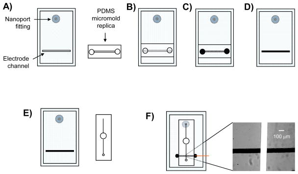
Silicon master wafers were fabricated using established lithographic techniques. Soft lithography was utilized for the fabrication of the PDMS fluidic channels and the fabrication of the embedded carbon ink electrode channels. Fluid access holes were drilled through microscope grade glass slides (50 mm wide, 75 mm long, 1 mm thick) using a 1 mm diamond tip drill bit and Dremel rotary tool (Dremel, Racine, WI). This glass substrate serves as a rigid foundation for the electrode layer and provides a means for external delivery of fluid (Figure 1A). A Nanoport fluidic connector was affixed over the hole onto the glass plate as per manufacturer instructions (Upchurch Scientific). A 20:1 (elastomer base: curing agent) layer of PDMS was placed on the glass substrate containing the Nanoports. This layer contained the recessed channel used for electrode fabrication (17.2 μm in depth × 134.6 μm in width). A replica mold of PDMS, containing the same dimensions as the electrode channel, was aligned over the 20:1 layer creating an encapsulated void (Figure 1B). Access holes (1/8″ diameter) at each end of the replica mold allow the application of a vacuum and the delivery of carbon ink. The carbon ink is added to one end of the encapsulated channel while the vacuum is applied to the opposite end, pulling the ink through and filling the channel (Figure 1C). After curing the electrode in a 75°C oven for one hour the replica mold is removed, leaving a solid carbon electrode embedded in the 20:1 PDMS layer (Figure 1D). The fluidic layer was cast in a 10:1 ratio of PDMS and removed from the master wafer. A 1/8″ diameter hole was punched through the center of the fluidic channel (Figure 1E) and was aligned over the bottom layer so that one end of the channel aligned with the Nanoport fitting and the other end of the channel crossed over the electrode (Figure 1F). A 20 gauge luer stub was used to punch a hole in the opposite end of the fluidic channel where a stainless steel pin, connected to polymer tubing, could be inserted. This steel pin serves both as a means to sample fluid from the reservoir and serves as a quasi-reference electrode in the amperometric setup.
Figure 1.
Steps involved in fabrication of PDMS-embedded carbon electrodes and assembly of the reservoir device (not to scale). A) PDMS layer where the carbon microelectrode will be embedded is reversibly sealed to a glass plate containing a Nanoport fitting. Also shown is the replica top micromold; B) The replica micromold is aligned and reversibly sealed over the electrode channel in the PDMS layer creating an encapsulated void; C) A vacuum is applied to one end of the top micromold while carbon ink is applied to the opposite end and pulled through the micromolds; D) After a heating step, the top micromold is removed leaving a cured carbon microelectrode structure embedded in the PDMS layer; E) The fluidic layer containing the 1/8″ diameter reservoir and the separate PDMS layer containing the carbon ink electrode are shown. F) The two PDMS layers are aligned and reversibly sealed together crating a fully assembled reservoir device. The inset shows fluorescein flowing through the fluidic channel and over the carbon ink microelectrode.
Experimental Setup
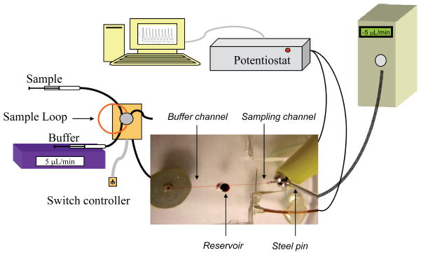
Figure 2 graphically depicts the experimental setup as well as a micrograph of the complete fluidic device. A 142.5 μm wide × 89.3 μm tall PDMS flow channel was reversibly sealed across both the inlet hole and the microelectrode of the PDMS sealed to the glass plate. Continuous flow of HBSS was generated with a syringe pump (Harvard Apparatus, Holiston, MA), with the buffer being routed through an off-chip, 6-port rotary valve (Valco Instruments, Houston, TX) that contains a 5 μL sample loop. The off-chip valve enables discrete injections of sample into the path of the HBSS that is led to fused silica capillary (50 μm i.d., 47 cm long). The capillary running from the injection valve is connected to the conned Nanoport fitting by a standard head nut (Upchurch Scientific). Amperometric detection was performed in a 2-electrode format with a CH 810B potentiostat (CH Instruments, Austin, TX). In all experiments, the carbon microelectrode sealed in the path of the fluidic channel functions as the working electrode while a hollow stainless steel pin functions as the quasi-reference (counter) electrode (the reference and auxiliary leads of the potentiostat were coupled together and attached to the steel pin). The supplied potentiostat software (CH Instruments) regulates the applied potential of the working electrode (typically +1400 mV) while measuring current generated at the working electrode surface. The measured current is plotted against time in a traditional current vs. time amperogram. Studies were initially performed to equalize the rates of the addition/withdrawal so the reservoir volume remains constant. A typical experiment utilized a continuous flow of buffer through the buffer channel from the Harvard syringe pump at 5.2 μL/min and constant sampling of the reservoir through the sampling channel by applying a negative pressure (−5.0 μL/min) to the channel outlet with a programmable Eldex syringe pump (Micropro 1000, Eldex, Irvine, CA). Standards or ATP stimulant are introduced to the reservoir via the injection valve and through the buffer channel.
Figure 2.
Amperometric setup for the microfluidic device. A syringe pump delivers buffer to a 6-port injection valve containing a 5 μL sample loop made of capillary tubing. As buffer passes through the sample loop it carries sample away from the injector to the fluidic device. The capillary tubing running from the injector is connected to a glass substrate by a Nanoport fitting. Buffer carrying analyte passes through the glass substrate, through the bottom layer of PDMS, and into the fluidic channel. As buffer reaches the 1/8″ reservoir it is drawn away by the negative pressure of the syringe pump connected to the steel pin at the terminal end of the fluidic channel. The working electrode residing in the path of the fluidic channel is connected to the potentiostat using a copper wire while the steel pin quasi-reference electrode is connected directly to the coupled potentiostat lead. The digital image displays the device in relation to amperometric setup (not to scale).
Solution Preparations
Hanks Balanced Salt Solution (HBSS, pH 7.4, Lonza, Walkersfield, MD) was used as the buffer for all experiments. Catechol, nitrite, and ATP stock solutions were made daily with water (10 mM). Standards were diluted to appropriate concentrations with HBSS directly before use. Nitric oxide stock solutions were made daily by adding diethylamine NONOate (DEANO) to 10 mL of deoxygenated buffer under a sealed volumetric flask, which was evacuated of oxygen, for 10 minutes in a 37°C water bath. The buffer solution was deoxygenated by purging argon gas into the solution for 15 min. DEANO is reported to have a half-life of 2 minutes at 37°C and follows first order kinetics for its rate of decay [15]. Because of this short half life almost all of the NONOate salt is dissociated after an incubation time of 10 minutes, allowing for relatively fast NO generation [15].
Immobilizing Cells in the Reservoir Design
Bovine pulmonary endothelial cells (bPAECs s; ATCC Manassas, VA) were purchased frozen at a concentration of 1×10⁶ cells/mL. Upon arrival the cells were thawed and seeded to a 75 cm2 tissue culture flask using a RPMI-1640 media supplemented with 10 mL penicillin/streptomycin (1% v/v) and 100 mL bovine serum albumin (10% v/v). Except for when passaging, harvesting, or changing media, the cells were kept in an incubator at 37°C and 5% CO2. When the cells reached ~80% confluence, they were harvested from the flask using a trypsin reagent pack (CC-5034; Lonza, Walkersville, MD). These cells were diluted to a concentration of ~1×10⁶ cells/mL in complete media and used for the chip studies.
To prepare the microchip for cell immobilization, 20 μL of a 100 μg/mL fibronectin solution was pipetted into the reservoir of the device. A small 1 mL microcentrifuge vial was inverted and placed over the top of the reservoir to minimize evaporation. The device was placed in the laminar flow hood for one hour after which time the cells were harvested from the culture flask using established methods [10]. The fibronectin was removed from the reservoir, and the harvested cell solution (1×10⁶ cells/mL in complete media) was pipetted into the reservoir. The 1 mL microcentrifuge vial was again inverted and placed over the reservoir. The device was allowed to sit in the incubator (37°C, 5% CO2) for one hour, after which time the device was removed and the media aspirated from the reservoir. The device was then placed on the stage of an inverted microscope so that the cells could be observed in the reservoir. A concentration of 1×10⁶ cells/mL allowed for a near-confluent layer of the cells to develop on the surface in a 1–2 hour period. A larger concentration of cells overcrowded the reservoir and did not allow the cells to immobilize while too low of a concentration led to a sparse distribution of cells on the reservoir surface. The detection of NO from these cells was accomplished by injecting a plug of ATP stimulant (100 μM) through the buffer channel while continuously monitoring the current produced at the microelectrode that is embedded in the reservoir sampling channel.
Results and Discussion
The goal of this work is to develop a hydrodynamic microfluidic device capable of performing electrochemical detection of NO released from a layer of endothelial cells that are immobilized in a manner that is straightforward and reproducible. In order to immobilize the endothelial cells in a specific area of the device, a 1/8″ diameter reservoir was placed in the center of a fluidic channel (Figures 1 and 2). The addition of this reservoir presented a few challenges in regard to conducting electrochemical detection. Integrating the electrode in the reservoir and immobilizing cells over the electrode would have issues with electrode fouling and would make quantitative analysis difficult. However, placing the electrode in the path of a fluidic channel downstream of the reservoir enabled us to circumvent these issues. This was accomplished by incorporating two flow channels on opposite sides of the reservoir (Figure 2). The buffer channel continuously introduced buffer to the reservoir. By utilizing an off-chip 6-port injector, a plug of standard or stimulant can be introduced to the reservoir through this channel. The sampling channel, where the electrode is integrated via the fabrication scheme shown in Figure 1, constantly withdraws buffer from the reservoir and this sampled stream passes over the carbon ink microelectrode. We have previously shown that there is no leakage around the chip/electrode interface when this type of PDMS-embedded carbon ink microelectrode is integrated in a microchannel [13]. In order to withdraw buffer/analyte from the reservoir and over the surface of the electrode, a stainless steel pin was inserted in the terminal end of the fluidic channel (see picture inset in Figure 2). This pin was connected to a programmable syringe pump that could be operated in a reverse (negative pressure) mode. The flow rates of the addition/withdrawal were fixed so that the reservoir volume remains constant over the course of the experiments.
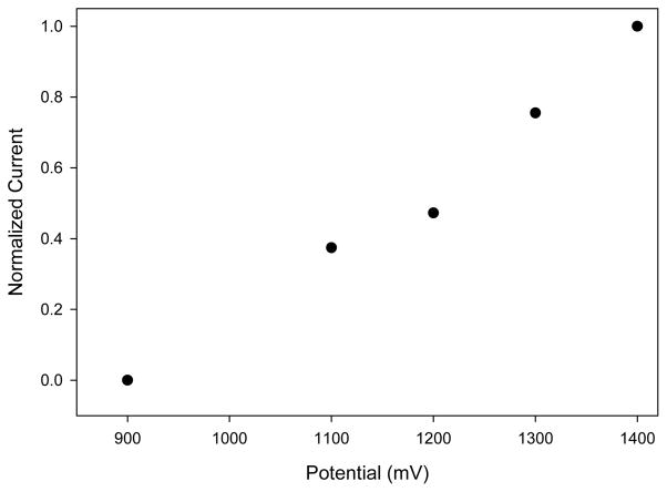
Since the reservoir design requires the use of a steel pin to draw fluid away from the reservoir, a reference electrode could not be placed in the outlet reservoir as in previous studies [13]. It was thus proposed that the stainless steel pin that serves to make the fluidic connection to the sampling channel could also be used as a coupled quasi-reference electrode. Because stainless steel is not a traditional reference electrode material, the optimal working potential for the carbon electrode had to be determined. Using the established flow rates, a hydrodynamic voltammogram (HDV) was constructed to determine the optimal working potential for NO detection using the steel pin quasi-reference electrode (Figure 3). The linear plot of the HDV is characteristic of the resistive carbon ink electrode and has been observed before, as reported in the literature [16–19]. As Figure 3 depicts, the optimal working electrode potential is shifted significantly to +1400 mV as compared to +900 mV when using a traditional Ag/AgCl reference electrode [12]. Potentials above +1400 mV resulted in slightly larger peaks but suffered from inconsistencies in both electrode response and electrode stability.
Figure 3.
Hydrodynamic voltammogram of NO using the reservoir device (potentials vs. steel pin quasi-reference).
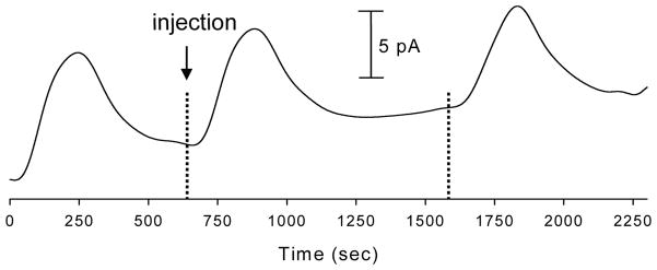
The device was characterized using NO standards produced from diethylamine NONOate salt. Figure 4 depicts a series of 36 μM NO injections with amperometric detection at +1400 mV (vs. steel pin quasi-reference) resulting in an average peak height of 8.44 ± 1.05 pA. Further experiments using DEANO-derived NO standards to construct a calibration plot (36 to 144 μM) yielded r2 values of 0.990 with an estimated LOD (S/N = 3) of 3.1 μM. Nitrite, which is an NO oxidation product, is a formidable interferent when performing electrochemical detection of NO. It is common to utilize electrodes coated with Nafion, a cation exchange polymer, to selectively transport the neutral NO over the negatively charged nitrite [10]. Using this device we have seen similar results from the injection of NO standards on both unmodified carbon ink electrodes and Nafion modified carbon ink electrodes. Experiments using both modified and unmodified electrodes for the detection of NO yielded an average peak height of 5.75 ± 1.31 pA for the unmodified electrode and 6.27 ± 0.52 pA for electrodes modified with 0.1% (w/v) Nafion. A t-test at 95% confidence determined that there is no significant different between the two peak heights. We previously showed that this concentration of Nafion effectively blocks the transport of 10 μM nitrite to a microelectrode housed in a fluidic channel of the same dimensions used here [12]. Nafion concentrations higher than 0.1% (w/v) led to inconsistent results when testing against NO and nitrite standards, likely due to the formation of a thick layer of Nafion that limits diffusion to the electrode surface at the flow rates used. The similarity in the unmodified and modified electrode response supports the idea that nitrite is contributing very little to the overall signal at the electrode. This is due to the fact that the buffer used for all of these experiments was de-oxygenated with argon and gas tight syringes, tubing, and connectors were utilized. Also, by taking into account the tubing and channel volume as well as the time from injection to detection it was determined that the longest time that cell-derived NO would spend in transit from the reservoir to the electrode is ~31 s. It has been reported previously that the lifetime of NO in degassed buffer can exceed 200 sec [20,21]. As a result of these observations, the data reported here were collected using unmodified electrodes.
Figure 4.
Consecutive injections of 36 μM NO standards. Buffer channel flow rate = 5.2 μL/min, Sampling channel flow rate = −5.0 μL/min, Detection potential = +1400 V (vs. steel pin quasi-reference).
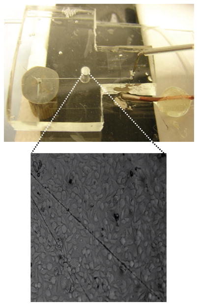
To demonstrate the ability to use this device as an endothelium mimic, cells were immobilized into the reservoir of each device (see experimental section for details) to generate a near-confluent layer of bovine pulmonary artery endothelial cells (bPAECs). Figure 5 shows a picture of a complete fluidic device along with a bright field micrograph of bPAECs immobilized in the reservoir. ATP stimulates the release of NO from bPAECs by binding to P2y purinergic receptors. In vivo, the NO that is produced at the endothelial cell lining is released into both the circulation and smooth muscle [10]. Injections of ATP standards (100 μM) were carried out using the same amperometric setup described earlier and depicted in Figure 2. Each experiment for correlating cell-derived NO concentration consisted of stimulating the cells with an injection of ATP and then comparing the cell-release NO signals to signals generated by NO standards. Stimulating cells in three different fluidic devices with 100 μM ATP yielded an average estimated release of 3.89 ± 0.66 μM. Micrographs of the cells were used to estimate the cell density in the reservoir. Taking into account the cell density of each device, the average concentration of NO released per cell was found to be ~120 pM.
Figure 5.
A picture of a completely assembled device with a bright field micrograph of endothelial cells immobilized onto the PDMS surface of a reservoir device.
Conclusions
This paper has described the fabrication and characterization of a microfluidic device that enables the detection of nitric oxide released from a near-confluent layer of endothelial cells. This type of in-vitro-based mimic of the vasculature will be useful in studies to determine the fate of extracellular NO produced at an endothelial lining as well as in studies to investigate the interaction of multiple cell types such as red blood cells and endothelial cells. The device utilizes a reservoir approach for cell immobilization as well two fluidic channels that address the reservoir. Carbon ink microelectrodes are integrated into one of the channels and the constituents of the reservoir are continuously monitored by constantly removing buffer/analyte from the reservoir and passing it over the electrode. It was shown that amperometric detection of NO can be carried out using non-traditional reference electrode materials, opening up alternatives for new fluidic designs. While we have shown that this device can be used to detect extracellular NO released from endothelial cells, future work will utilize such a device to implement bi-modal detection of both intracellular (fluorescence) and extracellular (amperometry) NO from the same sample of cells. Importantly, this approach is amenable to the creation of multiple reservoir arrays that enable the creation of varying environmental conditions for the cells in each reservoir and high-throughput screening.
Acknowledgments
This work is supported by funds from the National Institutes of Health, grant # 7R01EB004164-05.
References
- 1.Arnaud CH. Chem Eng News. 2007;85:14–19. [Google Scholar]
- 2.Blake AJ, Pearce TM, Rao NS, Johnson SM, Williams JC. Lab Chip. 2007;7:842–848. doi: 10.1039/b704754a. [DOI] [PMC free article] [PubMed] [Google Scholar]
- 3.Moehlenbrock MJ, Price AK, Martin RS. Analyst. 2006;131:930–937. doi: 10.1039/b605136g. [DOI] [PubMed] [Google Scholar]
- 4.Taylor AM, Blurton-Jones M, Rhee SW, Cribbs DH, Cotman CW, Jeon NL. Nat Methods. 2005;2:699–605. doi: 10.1038/nmeth777. [DOI] [PMC free article] [PubMed] [Google Scholar]
- 5.Li MW, Spence DM, Martin RS. Electroanalysis. 2005;17:1171–1180. [Google Scholar]
- 6.Cucullo L, Couraud P-O, Weksler B, Romero I-A, Hossain M, Rapp E, Janigro D. J Cereb Blood Flow Metab. 2008;28:312–328. doi: 10.1038/sj.jcbfm.9600525. [DOI] [PubMed] [Google Scholar]
- 7.Genes LI, Tolan NV, Hulvey MK, Martin RS, Spence DM. Lab Chip. 2007;7:1256–1259. doi: 10.1039/b712619k. [DOI] [PubMed] [Google Scholar]
- 8.Sprague RS, Ellsworth ML, Stephenson AH, Lonigro AJ. Am J Physiol. 1996;271:2717–2722. doi: 10.1152/ajpheart.1996.271.6.H2717. [DOI] [PubMed] [Google Scholar]
- 9.Moncada S, Palmer RMJ, Ferrige AG. Nature. 1987;327:524–526. doi: 10.1038/327524a0. [DOI] [PubMed] [Google Scholar]
- 10.Spence DM, Torrence NJ, Kovarik ML, Martin RS. Analyst. 2004;129:995–1000. doi: 10.1039/b410547h. [DOI] [PubMed] [Google Scholar]
- 11.Amatore C, Arbault S, Chen Y, Crozatier C, Tapsoba I. Lab Chip. 2007;2:233–238. doi: 10.1039/b611569a. [DOI] [PubMed] [Google Scholar]
- 12.Christodoulou D, Kudo S, Cook JA, Krishna MC, Miles A, Grisham MB, Murugesan R, Ford PC, Wink DA. Electrochemical Methods for Detection of Nitric Oxide. In: Packer L, editor. Methods of Enzymology (v. 268): Nitric Oxide, Part A Sources and Detection of NO; NO Synthase. Academic Press; San Diego: 1996. [DOI] [PubMed] [Google Scholar]
- 13.Hulvey MK, Genes LI, Martin RS, Spence DM. Analyst. 2007;132:1246. doi: 10.1039/b711148g. [DOI] [PubMed] [Google Scholar]
- 14.Martin RS, Root PD, Spence DM. Analyst. 2006;131:1197–1206. doi: 10.1039/b611041j. [DOI] [PubMed] [Google Scholar]
- 15.Keefer LK, Nims RW, Davies KM, Wink DA. In: Methods in enzymology Part A: Sources and detection of NO; NO synthase. Packer L, editor. Academic Press; 1996. [Google Scholar]
- 16.Seddon BJ, Osborne MD, Lagger G, Dryfe RAW, Loyall U, Schaefer H, Girault HH. Electrochim Acta. 1997;42:1883–1894. [Google Scholar]
- 17.Wang J, Tian B, Nascimento VB, Angnes L. Electrochim Acta. 1998;43:3459–3465. [Google Scholar]
- 18.Wang J, Tian B, Sahlin E. Anal Chem. 1999;71:5436–5440. doi: 10.1021/ac990807d. [DOI] [PubMed] [Google Scholar]
- 19.Kovarik ML, Li MW, Martin RS. Electrophoresis. 2005;26:202–210. doi: 10.1002/elps.200406188. [DOI] [PubMed] [Google Scholar]
- 20.Kotsis DH, Spence DM. Anal Chem. 2003;75:145–151. doi: 10.1021/ac0258249. [DOI] [PubMed] [Google Scholar]
- 21.Thoma DD, Xiaoping L, Kantrow SP, Lancaster JR. Proc Natl Acad Sci. 2001;98:355–360. doi: 10.1073/pnas.011379598. [DOI] [PMC free article] [PubMed] [Google Scholar]


