

Abstract
Patterning of gene delivery on sub-millimeter length scales within tissue engineering scaffolds can provide a fundamental technology to recreate the complex architectures of tissues. Surface-mediated delivery of lipoplexes mixed with fibronectin was investigated to pattern vectors within 250 µm channels on poly (lactide-co-glycolide) (PLG) bridges. Initial studies performed in vitro on PLG surfaces indicated that a DNA density of 0.07 µg/mm2 inside each channel with a weight ratio of DNA to fibronectin of 1:20 maximized the number of transfected cells and the levels of transgene expression. Patterned vectors encoding for nerve growth factor (NGF) resulted in localized neurite extension within the channel. Translation to 3D multiple channel bridges enabled patterned transfection of different vectors throughout the channels for ratios of DNA to fibronectin of 1:4 and multiple DNA depositions, with a large increase of neural cell bodies and neurite extension for delivery of DNA encoding for NGF. In vivo, the immobilization of non-viral vectors within the channels resulted in localized transfection within the pore structure of the bridge immediately around the channels of the bridge containing DNA. This surface immobilization strategy enables patterned gene delivery in vitro and in vivo on lengths scales of hundreds of microns and may find utility in strategies aims at regenerating tissues with complex architectures.
Introduction
Tissue engineering and gene delivery can be combined to create a controllable microenvironment with structural and biological cues that lead to tissue formation [1]. The pore size and structure of a scaffold can be designed to physically orient and organize cells into complex architectures, such as those observed in the nervous and vascular systems. Gene delivery from the scaffold can target infiltrating cells to induce the expression of tissue inductive factors to promote cellular processes that synergize with the scaffold architecture to organize complex tissue structures. In spinal cord regeneration, bridges with multiple channels orient the extension of axons across an injury [2–6], while gene delivery from the bridges has the potential to induce the localized long-term expression of factors that promote neuron survival and neurite outgrowth [4, 7].
The spinal cord, however, has a complex architecture, with motor and sensory tracts that are located at distinct positions in the spinal cord and consist of different types of neurons that express specific receptors and integrins. The functional spinal tracts, such as the corticospinal and rubrospinal motor tracts, require different neurotrophins for maximal regeneration [8]. As an example, nerve growth factor (NGF) binds to tropomyosin receptor kinase A (trkA) and plays an important role in the survival and outgrowth of sensory neurons, while motor neurons contain trkB and trkC receptors that mainly respond to brain-derived neurotrophic factor (BDNF) and neurotrophin-3 (NT-3), respectively [9]. Patterned expression of neurotrophic factors within channels positioned to correspond with the location of the tracts within the spinal cord may enable the factors to be available in the appropriate spatial context, which could facilitate regeneration.
Initial approaches to directing neurite outgrowth have employed surfaces patterned with adhesion molecules, such as laminin [10–13], or non-adhesive molecules, such as PEG, on an otherwise adhesive surface [14]. More recently, the surface immobilization of gene therapy vectors have been employed in vitro to pattern gene expression on surfaces (2D) using methods, such as spotting, printing, microfluidics, or pinning [10, 15–19]. Patterned expression of neurotrophic factors orients and promotes directed neurite outgrowth towards, within, and along the pattern in an in vitro co-culture model [16, 20]. Expression of the inhibiting molecule brevican stimulates nerve growth outside the pattern [10]. Although these strategies have been applied in vitro to 2D surfaces, the long-term application of this technique will require the translation to 3D systems and in vivo gene expression.
This report investigates the patterning of gene delivery on the sub-millimeter scale within a tissue engineering scaffold in vitro, and in vivo using a spinal cord injury model. Fibronectin was employed to facilitate localization of DNA within the channels, and enhance transgene expression [7, 21, 22]. Initial studies were performed in vitro using 2D poly (lactide-co-glycolide) (PLG) disks and 3D bridges to identify key parameters such as the fibronectin concentration and the DNA dose. These bridges were highly porous with multiple channels, which allowed them to maintain apposition with the host tissue, following implantation into a lateral hemisection in a spinal cord. The bridges prevented cavity formation, supported cell infiltration into the pores and channels, and had regenerating axons within the channels [4, 23, 24]. Additionally, plasmid and lipoplex delivery from these bridges promoted transient transgene expression at the implant site [4, 23, 24], with Schwann cells, macrophages, and fibroblasts identified as the cell types primarily transfected [4]. Patterned gene delivery from channels of the bridge could be employed to address the complex architecture of the spinal cord, and may be an enabling tool for regeneration of complex tissues, as multiple factors can be simultaneously delivered that target specific regions of the tissue.
Materials and methods
Fabrication of PLG disks and multiple channel bridges
Multiple channel PLG disks and bridges were fabricated as previously described [4, 7, 25], using high molecular weight PLG (75:25 mole ratio of D, L-lactide to glycolide, 0.76 dL/g, Lakeshore Biomaterials, Birmingham, AL). For 2D experiments in vitro, PLG disks with 6 channels of 250 µm width, 150 µm height, and 10 mm length were fabricated by heat molding, using a polydimethylsiloxane (PDMS) (Krayden, Glenview, IL) mold that was fabricated with photolithography techniques as previously described [25]. PLG pellets were positioned onto the PDMS template, heated to 82°C, pressed into a flat disk using a 5 kg weight with the temperature being decreased from 82°C to 37°C in four incremental steps, and kept at 37°C overnight.
Multiple channel bridges were fabricated using a gas foaming/particulate leaching method [4, 7]. A mixture of PLG microspheres and salt particles (63–106 µm) was loaded into a custom made Aluminum mold with Delrin pin guides using a layer-by-layer technique. Subsequent to gas foaming and pin removal, the porogen was leached from the bridge for one hour.
DNA patterning in channels
Plasmids were amplified in Escherichia coli DH5α, purified with Qiagen (Santa Clara, CA) reagents, and complexed with Transfast (Promega, Madison, WI) in a w/v ratio of 1:1.5. After incubation for 15 minutes, 10 µL of fibronectin (2 µg/µL) (Sigma-Aldrich, St. Louis, MO) was added to the complexes and pipetted into the channels of the disks that were deposited in 6 well plates. A Stripper pipet with tips of 150 µm (Mid-Atlantic Diagnostics, Mount Laurel, NJ) diameter was used for deposition into the channels of the bridge.
A single DNA deposition was performed within the channels of the disks, while multiple depositions were performed in the channels of the bridge. For bridges, DNA was deposited only into the 2 outer channels of the middle row with a concentration of 1 or 5 µg DNA per 20 µg fibronectin (2 µg/µL), Six consecutive deposition steps of 0.8 µL were performed, alternating between the entrances to the channel. After DNA deposition, the bridge or disk was dried and washed twice before cell seeding in vitro. To visualize the localization of fibronectin and DNA respectively, a Sirius red stain (Sigma-Aldrich, St. Louis, MO) was performed and rhodamine labeled DNA (Nucleic Acid Labeling Kit, Cy™3, Mirus Bio, Madison, WI) was analyzed by fluorescence microscopy.
In vitro transfection studies
HEK293T cells were seeded onto the PLG disks and bridges to analyze transfection in vitro. The number of transfected cells, and the amount of protein produced were quantified for multiple DNA concentrations (0, 0.25, 0.5, 1, 3, 5 µg DNA per 20 µg fibronectin). After deposition and drying of the DNA into the channels of the disk, 200,000 cells were seeded in each well (6 well plate), containing one disk. For co-culture studies, the disks were transferred to a 24 well plate before cell seeding (60,000 HEK 293T cells per well) to reduce the required number of neurons. Bridges were sectioned longitudinally across the middle row of channels before seeding approximately 300,000 cells on each surface. The cells were pipetted onto the surfaces in two steps of 6 µL, with a third deposition of Dulbecco's Modified Eagle Medium (DMEM) to allow the cells to adhere before adding 3mL of media to the 6 well plates. After 48 hrs, an MTT stain (Sigma-Aldrich, St. Louis, MO) was used to visualize the location of metabolically active cells.
The location and number of transfected cells on the surfaces of the disks and inside the bridges were observed with the use of reporter genes, such as plasmid encoding for pβgal, and red (pDsRed) and green (pGFP) fluorescent protein, using an Xgal stain and fluorescent microscopy, respectively. To quantify cross contamination, pDsRed and pGFP were deposited in alternating channels of the patterned disks at a concentration of 1 µg DNA per 20 µg fibronectin. Cells transfected with the plasmid from an adjacent channels were counted for both washed and non-washed surfaces. In bridges, one channel was deposited with pDsRed while the opposite channel contained pGFP.
To quantify the levels of transgene expression, plasmid encoding for firefly luciferase (pLuc) was used, while the levels of luciferase production were measured with a Luciferase Assay System (Promega) and luminometer [7]. pLuc was deposited in one channel of the PLG disk to quantify the levels of transgene expression in one channel. The relative light unit (RLU) measurements were normalized to the total protein amount, which was measured by the enhanced test tube protocol of the BCA (bicinchoninic acid) protein assay (Pierce, Rockford IL).
In vitro neurite outgrowth
In vitro neurite outgrowth was investigated by delivering a plasmid encoding for NGF (pNGF) in a neuronal co-culture model. pNGF (a gift from Dr. Hiroshi Nomoto (Gifu Pharmaceutical University, Japan)) with an RK5 vector backbone, full-length mouse NGF, and CMV promoter was deposited in the middle channel of the PLG patterned disks. In the case of disks, 1 µg of DNA was mixed with 10 µL fibronectin (2 µg/µL) and deposited in the middle channel only, while in the case of bridges, 5 µg of DNA was mixed with 10 µL fibronectin and deposited to each channel in 6 repetitive steps of 0.8 µL. The surfaces were washed twice before cell seeding on the entire surface.
The neuronal co-culture model consisted of primary dorsal root ganglion (DRG) neurons cultured with HEK293T cells. HEK293T cells were transfected in order to produce NGF and promote neurite outgrowth of the co-cultured neurons, and were used because they do not basally support neuronal survival, which allowed for connecting the behavior of DRG neurons with the patterned NGF expression [16]. Primary DRGs were isolated from E8 white leghorn chicken embryos (Phil’s fresh eggs farm, Forrester, IL) and dissociated into neurons as described before [25]. After washing the surfaces twice with PBS, HEK293T cells and DRG neurons (4×10⁴ neurons/well for disks or approximately 150,000 neurons/bridge) were seeded within 24 hours of each other to create a co-culture. A mixture of fibronectin and transfast without DNA was deposited as a control.
To visualize neurite extension, neurons were fixed and stained for neuron-specific class III β-tubulin after 48 hours of co-culture. In the case of a co-culture on PLG disks, the primary antibody, TUJ1 (Covance, Berkely, CA), was diluted in 5% normal goat serum (Vector Labs, Burlingame, CA) in PBS and applied for 1 hour, followed by incubation of TRITC-conjugated goat anti-mouse secondary antibody (red fluorescent) (Jackson Immunoresearch, West Grove, PA) for 30 min. Total neurite extension was quantified for each channel using Image J with a Neuron J plug-in [26], and normalized to the total neurite extension in all channels. In the case of bridges, the primary antibody, TUJ1, was diluted in 5% normal horse serum (Vector Labs, Burlingame, CA), followed by incubation of a secondary biotinylated anti-mouse antibody (Vector Labs, Burlingame, CA) for 45 min, and an immunoperoxidase stain using the Avidin-Biotin-peroxidase Complex (ABC) system, which reacts with 3,3’-diaminobenzidine (DAB) to produce a brown stain.
Rat spinal cord hemisection model
A rat spinal cord hemisection model was applied to analyze patterened transfection in vivo. Surgery was performed as previously described [7]. Thirteen female Long-Evans rats (Charles River, 180–200 g) were treated according to ACUC guidelines at the University of California Irvine and Northwestern University. A laminectomy was performed at T9-10 to expose the cord and a 4 mm long spinal cord segment, lateral of the midline, was removed to create a hemisection and implant the bridges.
Quantification of transgene expression in vivo
Transgene expression in vivo was quantified after one week by depositing pluc/fibronectin inside all the channels of the bridge, which was implanted in the spinal cord injury. After retrieving the cords, the bridges were removed from the tissue and the tissue was cut into different segments to analyze the production of luciferase for each segment separately as previously described [7].
Immunohistochemistry to visualize patterned transfection in vivo
One week post-injury, rats were euthanized, and the spinal cord section containing the injury site (T9-T10) was frozen in isopentane (Fisher Scientific), and cryopreserved in optimum cutting temperature (O.C.T.) compound. The cord was sliced transversally to the channel orientation in 10 µm thick sections using a cryostat (Micron, Microm HM 505 N). To visualize all cells, sections were stained with Hoechst (1:2000 dilution, Molecular Probes, Invitrogen, Carlsbad, CA). Transfected cells were stained with an immunoperoxidase stain and polyclonal rabbit anti-EGFP (Invitrogen, Carlsbad, CA) as a primary antibody in combination with a tyramide signal amplification method (TSA™ Kit #12, Invitrogen). Briefly, a horse radish peroxidase (HRP)-goat anti-rabbit IgG and Alexa Fluor® 488 tyramide were used to induce an enzyme-mediated detection based on the catalytic activity of HRP to generate high-density labeling of a target protein or nucleic acid sequence in situ. As a control, plasmid encoding for β-gal was applied inside the two outer channels of the middle row, and stained for GFP. Phase images were overlaid on fluorescent images to visualize the location of the channels.
The patterning of gene delivery around the channels with immobilized DNA was characterized by determining the fluorescence signal as a function of distance around the channels loaded with DNA, and with the central channel that did not receive DNA. For each rat, three images of channel cross sections were selected for quantification. The images were selected from the center region of the bridge with a minimum separation of 400 µm. The two channels at each end of the middle row had been loaded with pGFP and were analyzed. The center channel was employed as a control, as this channel is farthest from the channels loaded with DNA. To measure the normalized integrated intensity of the GFP stain around the channels, the radial profile plot plugin of Image J was used from the edge of each channel to a 160 µm distance away from the channel. The measured intensity was normalized by the maximal intensity on that slide to account for variations in signal intensity between slides. The background intensity was subtracted from this normalized intensity, with background determined by averaging the intensity obtained on a negative control slide (i.e., patterned pß-gal). The average of the patterned channels containing pGFP and the middle channel without DNA for all four rats was plotted.
Statistical analysis
Statistical analyses were done using statistical package JMP (SAS, Cary, NC). For multiple pairs comparison, an ANOVA with post-hoc Tukey test was performed with a p-level of 0.05. A t-test was performed to analyze differences between individual pairs. Error bars represent standard deviations in all figures.
Results
Patterned DNA in channels of three dimensional bridge
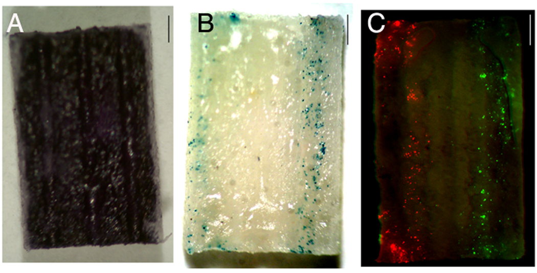
Initial studies were done with bridges to determine which fibronectin concentration maximized the localization of DNA within the channels of the bridge. Rhodamine labeled plasmid (1 µg) was complexed with Transfast, mixed with 10 µL fibronectin (2 µg/µL), and deposited within the 250 µm wide channels of the bridges. For the 3D porous bridges, a concentration of 2 µg/µL fibronectin was necessary to increase the viscosity of the mixture and enable localization of both the fibronectin and DNA inside the channels. After pipetting the mixture of lipoplexes and fibronectin into the two outer channels of the middle row, and washing the bridge twice with PBS, both fibronectin (Sirius Red stain) and DNA remained inside these channels (Fig. 1, a–b). A homogeneous coating throughout the channel was obtained after 6 alternating depositions of 0.8 µL in each channel, which corresponds to approximately 0.4 µg DNA per channel.
Figure 1.
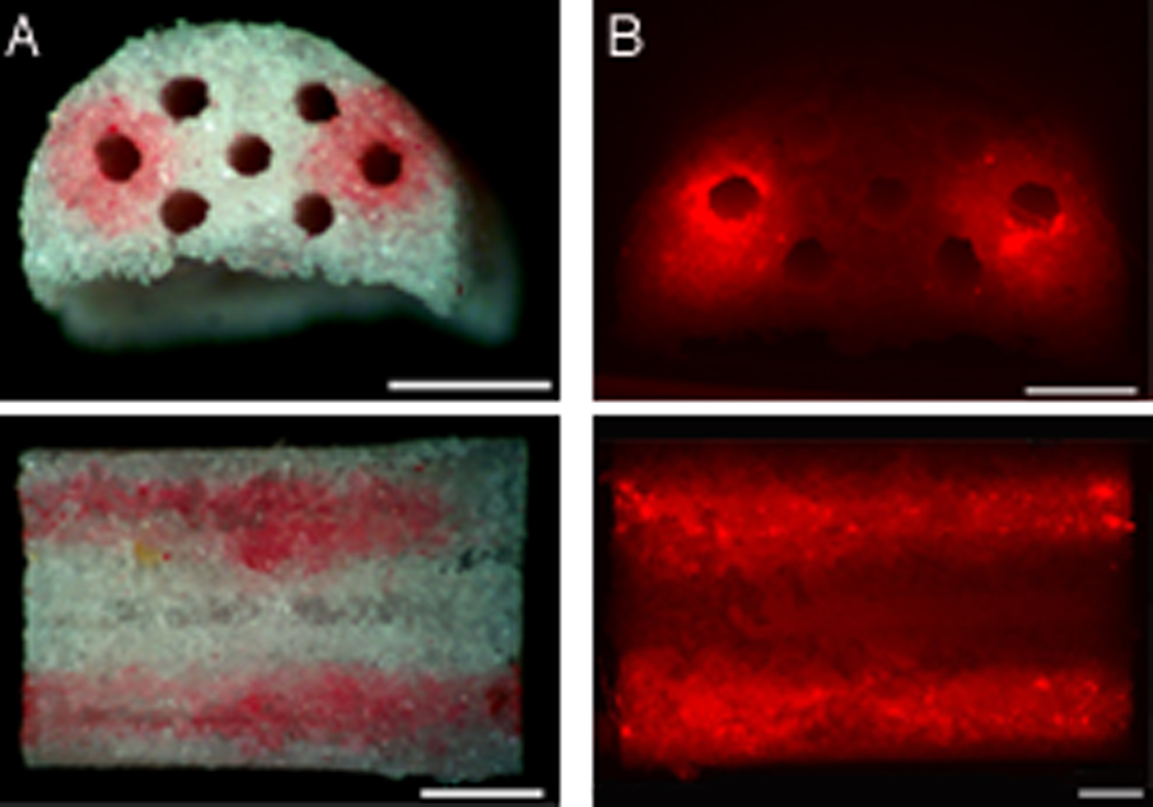
Patterning of fibronectin/lipoplex mixture within the outer two channels of the middle row of the multiple channel bridge. Bridges were washed twice after deposition. A) Sirius red stain of fibronectin inside the deposition channels. From top to bottom: side view and cross section of bridge. Scale bars: 1 mm. B) Fluorescence image of rhodamine labeled DNA (red), complexed with Transfast and mixed with fibronectin inside deposition channels. From top to bottom: side view and cross section of bridge, Scale bars: 500 µm.
Two dimensional patterned transfection In vitro
Initially, transfection was investigated on disks (i.e., two-dimensional) to identify the DNA dose and determine whether transfection was localized within the pattern. The location of transfected cells within the pattern and transgene expression were quantified using pβgal and pLuc respectively. Transfected cells (blue) were visualized following Xgal staining, and localized within the channel into which the DNA was deposited (Fig. 2, a). The number of transfected cells, and the amount of protein produced were quantified for multiple DNA concentrations (0, 0.25, 0.5, 1, 3, 5 µg DNA per 20 µg fibronectin), which corresponds respectively with approximately 0, 9, 18, 32, 69, 89 ng DNA per channel based on the volume of one channel. An increase of DNA dose led to a greater number of transfected cells, which was maximal for a DNA dose equal to and greater than 1 µg DNA per 20 µg fibronectin (Fig. 2, b), with no significant differences between 1 and 5 µg DNA per 20 µg fibronectin (p>0.05), and a total number of transfected cells between 400 and 600 per channel (Fig. 2, b). The number of transfected cells was reduced approximately 35% relative to the unwashed surfaces (data not shown). This reduction in transfected cells with washing likely results from a loss of DNA during the wash step, which was previously reported to be approximately 20% [24]. The protein production was the greatest for 3 µg DNA per 20 µg fibronectin, with levels of 3.7×10⁷ ± 6.3×10⁶ RLU/(mg protein in one channel) (Fig. 2, c). All other conditions with DNA had expression levels above 1×10⁷ RLU/(mg protein in one channel)
Figure 2.
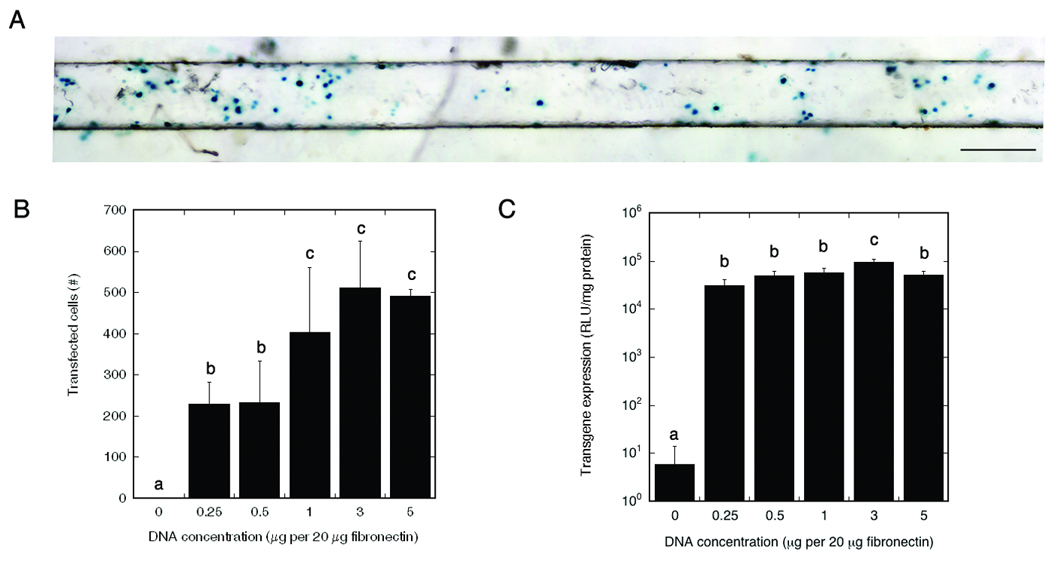
Number of transfected cells and levels of transgene expression in channel of PLG disk for multiple DNA doses. A) Transfected cells (blue) in channel, scale bar: 250 µm. B) Quantification of number of transfected cells for different doses of pβgal. C) Levels of transgene expression after deposition of multiple doses of pLuc in one channel of the disk. Significant differences, based on a Tukey multiple comparisons analysis, are denoted by different letters (p<0.05).
Cross-contamination of patterned transfection
The deposition of multiple plasmids into different channels was subsequently investigated to analyze localized and patterned transfection. Two plasmids, pDsRed (red) and pGFP (green), were deposited in alternating channels at a concentration of 1 µg DNA per 20 µg fibronectin. Surfaces that were washed twice (Fig. 3, a) were compared with unwashed surfaces (Fig. 3, b). The number of transfected cells within each channel was similar to that reported in Figure 2 for 1 µg DNA per 20 µg fibronectin. To analyze cross-contamination, cells that were transfected with pGFP in a channel containing pDsRed, or with pDsRed in a channel containing pGFP, were quantified. The washed surface had an average of 10 ± 2 transfected cells outside the pattern per channel, while the non-washed surfaces contained 14 ± 2 outliers per channel (Fig. 3, c). These outliers represent less than 5% of the total number of transfected cells inside the appropriate pattern, and did not show significant differences of cross-contamination for the comparison of washed and non-washed surfaces.
Figure 3.
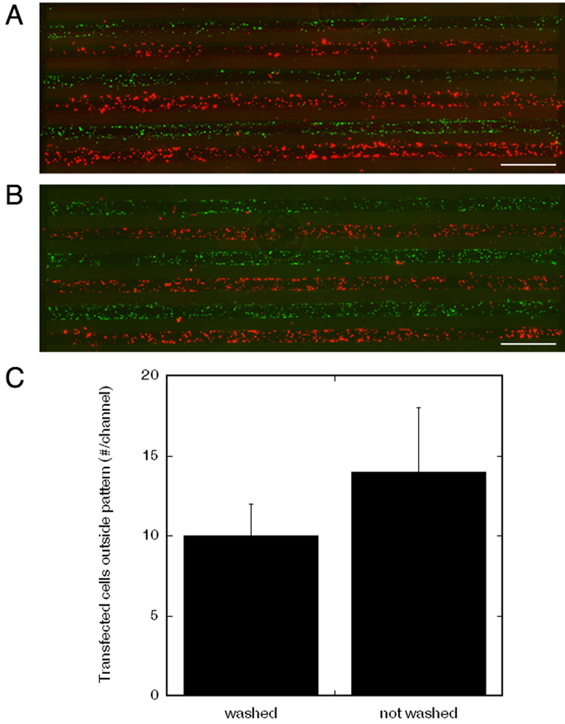
Alternating deposition of two plasmids, pGFP and pDsRed, in channels of PLG disk. Transfected cells by pGFP (green) and pDsRed (red) in channels of disks that were washed (A) or not washed (B) prior to cell seeding, scale bars: 1 mm. C) Quantification of cross-contamination: the numbers of cells transfected by pGFP in the channel containing the pDsRed, and vice versa, for both washed and non washed surfaces prior to cell seeding. No significant differences were observed based on a t-test (p<0.05).
Two dimensional patterned neurite outgrowth In vitro
Dorsal root ganglion (DRG) neurons were seeded on a pNGF pattern to analyze whether neurite outgrowth was localized within the channel in which transfection occurred. pNGF was deposited in the middle channel of the PLG disk at a concentration of 1 µg DNA per 20 µg fibronectin. The surfaces were washed twice before cell seeding on the entire surface. A large amount of neurite extension (red) was observed within the channel containing the pNGF (Fig. 4, a), with an average total neurite length of approximately 13 mm in the entire channel. A control performed by depositing fibronectin with transfast without DNA resulted in no neurite outgrowth (Fig. 4, b). Quantification of neurite extension revealed that 53 ± 4% of the total neurite length in all channels was located in the channel containing the pNGF. The adjacent channels at a distance of 250 µm and 750 µm from the central pNGF channel, had neurite extension that was 13 ± 5% and 10 ± 5% respectively of the neurite extension in the central pNGF channel (Fig. 4, c).
Figure 4.
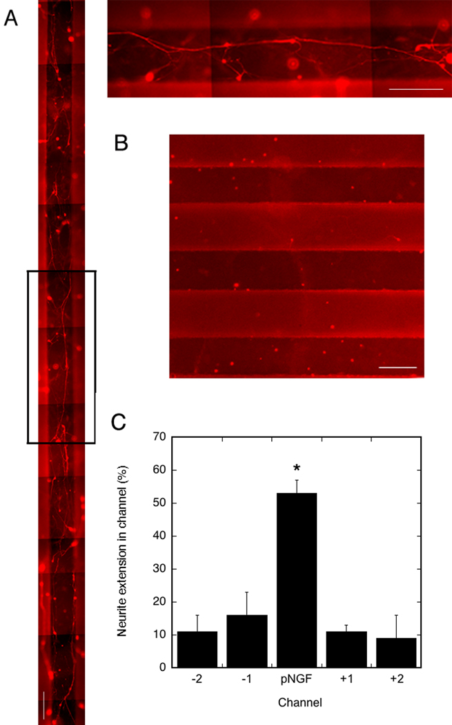
Neurite outgrowth in channels of PLG disks. A) left: neurite extension (red) in channels of disk with only the middle channel containing pNGF, top right: magnification of area in black square. B) neurite extension in channels of disk without pNGF deposition. Scale bars: 250 µm. C) Quantification of total neurite extension in each channel, normalized to the total neurite extension in all channels. Significant differences based on a Tukey multiple comparisons analysis are denoted by an asterisk (p<0.05).
Patterned transfection and neurite outgrowth in bridge channels
The procedures for patterning disks were subsequently adapted to the 3D bridge to obtain patterned transgene expression inside the channels of the multiple channel bridge in vitro. The lipoplex/fibronectin mixture was pipetted into the two outer channels, and bridges were sectioned longitudinally across the middle row of channels. Cells seeded on the bridge cross-sections were homogeneously deposited across the surface (MTT stain) (Fig. 5, a). Deposition of pßgal inside the outer channels enabled patterned transfection of the cells localized in these channels only (blue) (Fig. 5, b). A concentration of 5 µg DNA per 10 µL fibronectin (2 µg/µL) and 6 depositions of 0.8 µL per channel was necessary to obtain consistent patterned transfection throughout the channel, which corresponds to approximately 1.3 µg of DNA. Cells on the bridge but not present in the targeted channels were not transfected. Deposition of multiple genes (pDsRed, pGFP) within different channels of the bridge resulted in localized patterned transfection (red and green respectively) (Fig. 5, c).
Figure 5.
Patterned transgene expression in channels of 3D multiple channel bridges. A) MTT stain for metabolically active cells, 48 h after cell seeding (dark blue). B) Transfected cells (blue) 48 h after cell seeding, with pβgal deposited only in the two outer channels of the middle row of the bridge. C) Transfected cells (green respectively red), for 2 plasmids, pGFP and pDsRed, deposited in the two outer channels of the middle row. Scale bars: 1 mm.
DRG neurons were seeded onto bridges containing pNGF inside the two outer channels to analyze neurite survival and extension. The number of neuronal cell bodies attached to the polymer significantly increased in the presence of pNGF. Neurons present into the two outer channels demonstrated a higher degree of neurite extension compared to the middle channel that was not patterned with pNGF (Fig. 6). Only a sparse number of neuronal cell bodies were visualized on the control bridges with no neurite extension observed.
Figure 6.
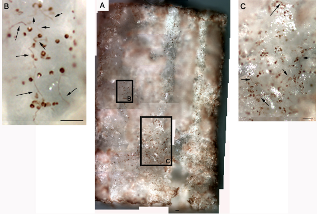
Neurite outgrowth in channels of multiple channel bridge. Panel A represents a composite image of the bridge, while the other panels are high magnification images of the sections indicated in the composite. Neurite outgrowth in Panels b and c are indicated by arrows. Scale bars: 80 µm.
Transfection after spinal cord injury
Bridges with lipoplexes deposited inside its channels were implanted inside the rat spinal cord hemisection model to investigate patterned transfection in vivo. Deposition of pluc/fibronectin in all 7 channels resulted in transfection inside the bridge at 1 week post-injury, with lower levels of transgene expression adjacent to the bridge (Fig. 7). After quantifying the extent of transgene expression, we subsequently investigated the potential of patterning delivery by depositing pGFP/fibronectin, deposition only in the two outer channels of the middle row. Nuclei staining indicated that cells were present throughout the pores and inside the channels of the bridge (Fig. 8, a). An overlay of fluorescence GFP image with a brightfield image enabled the identification of relative position of transfected cells within the bridge (Fig. 8, b, c). Channels filled with DNA encoding for -gal did not have positive staining for GFP (Fig. 8, d).
Figure 7.
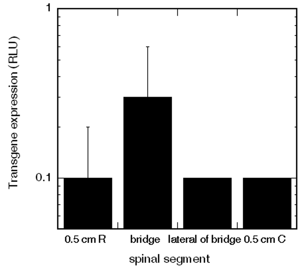
Transgene expression in vivo after 1 week of implantation. Channels of bridge were deposited with plasmid encoding for luciferase. RLU levels below 0.05 are considered background levels [4].
Figure 8.
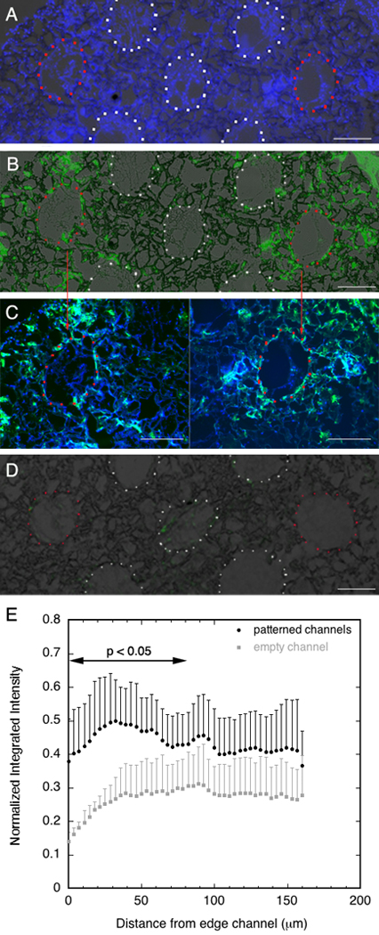
Patterned transfection in vivo. Cross section of bridge with cell infiltration at one week (blue) and transfected cells (green), obtained by a brightfield overlap on a fluorescent image. Channels containing DNA are marked with red dots and channels without DNA with white dots. A) Nuclei staining indicated that cells were present throughout the pores and inside the channels of the bridge. B–C) Transfected cells were observed within the pore structure of the bridge immediately around the channels (B) and overlapped with the Hoechst stain (C). D) GFP stain of bridge with two outer channels filled with lipoplexes encoding for β-galactosidase. E) Quantification of the normalized integrated intensity around the patterned channels and empty channel in the middle row. The intensity was measured from the edge of the channels to a 160 µm distance from each channel. Significant differences were observed based on a t-test (p<0.05) up to a distance of 81.8 µm from the edge of the channels.
Patterned transfection within and around channels was mainly observed in the center of the bridge. For channels with immobilized pGFP, transfected cells (green) were mostly observed within the pore structure of the bridge immediately around the channels (Fig. 8, b,c). For channels without immobilized DNA, transfected cells were not observed within the channels. In addition, transfected cells were observed at the edges of the bridge and outside the bridge, but demonstrated less patterning compared to the center of the bridge, which likely results from some release of lipoplexes at the interface between the bridge and the host tissue. Therefore, 3 cross sections for the center of the bridge were selected for quantification with Image J. The measurements of the normalized integrated intensity from the edge of the channel to a 160 µm distance away from the channel revealed that transgene expression is localized around channels containing DNA (Fig. 8, e). The left and right patterned channels containing pGFP had a greater intensity compared with the center channel that did not contain pGFP (p<0.05), with the difference being greater closest to the edge of the channels and statistically significant for a distance of 81.8 µm from the edge. GFP expression was observed at distances of a couple hundred microns from the edge of the channel; however, the intensity was significantly reduced relative to that at the channel edge, and was not significantly different between the DNA loaded and unloaded channels. Taken together, this distribution of transfected cells within and around the channels demonstrated the feasibility of surface immobilization to pattern gene transfer In vitro and in vivo.
Discussion
The combination of tissue engineering and gene therapy has proven to induce high levels of localized transgene expression for an extended duration, resulting in functional responses, such as angiogenesis and bone formation [27–29]. More recently, tissue engineering scaffold have been fabricated with complex architectures in order to provide physical guidance and enhance the ability to reproduce the complexity of several tissues [4, 6, 30–32]. Microfabrication techniques, such as inkjet printing and laser ablation, are being further developed to create scaffolds with controllable feature size and patterned topography [33, 34]. The combination of 3D scaffolds with complex geometries and patterned gene delivery may provide the physical and chemical guidance cues necessary for tissue engineering but remains challenging as vector-material interactions have to locally maintain the vector and retain vector activity in effective concentrations within the pattern until cells infiltrate the scaffold to internalize and express the gene [1].
In this report, a mixture of lipoplexes and fibronectin was pipetted within the 250 µm wide channels of 3D spinal cord bridges. Fibronectin was used, as it has previously been described to enhance transgene expression for lipoplexes dried onto PLG surfaces [7]. A high concentration of fibronectin was necessary to increase the viscosity of the mixture in order to maintain the lipoplexes in the channels of the bridge (Figure 1). In vitro transfection studies using 2D patterned PLG disks revealed an increased number of transfected cells with increasing DNA dose that reached a maximum probably due to the saturation of DNA bound in the channel and/or the toxicity of the DNA at high concentrations. Accordingly, the levels of transgene expression increased with DNA dose but decreased at higher concentrations (Figure 2).
Patterning plasmids within the bridge channels may enable channels to be tailored for the complex architecture of the spinal cord (e.g., propriospinal, rubrospinal, corticospinal) that correspond to the spatial position in the spinal cord. Immobilizing multiple plasmids in different channels demonstrated less than 5% cross-contamination, which may suggest that the DNA is locally released and taken up by the cells without diffusing to the adjacent patterns (Figure 3). Interestingly, similar numbers of transfected cells were observed outside the patterns whether the surfaces were washed or not washed prior to cell seeding. A challenge with surface delivery is that the material must bind DNA to maintain it locally, yet must allow for internalization [1]. For this system, the DNA that is released from the surface in vitro would be diluted in the bulk media and thus not contribute significantly to transfection [35]. Translation of this immobilization technique to 3D multiple channel bridges required the deposition of a higher DNA dose in multiple steps as the bridge is 90% porous [4], and allows for some transport of DNA away from the channel thereby lowering the transfection efficiency (Figure 4).
Patterning of pNGF inside the channels led to a greater number of attached neuronal cell bodies and neurite extension on the disks (Figure 5) and within the bridges (Figure 6), consistent with the effects of NGF [36]. Many applications of gene delivery in regenerative medicine focus on growth factors, as the endogenous cells would function as bioreactors that secrete these proteins to condition the microenvironment. Neurite outgrowth was observed in adjacent channels; however, the extent of neurite outgrowth was reduced 5-fold relative to the central channel. This neurite extension in the adjacent channels was likely induced by diffusing NGF, as control disks did not support neurite outgrowth in any channels. A distance effect on neurite outgrowth has previously been characterized and is dependent on the size of the channel [16, 37].
Lipoplexes patterned within the channels were able to promote transgene expression within the spinal cord 1 week post-injury, which was localized within or adjacent to the channels containing DNA. Lower levels of expression were observed in the segments adjacent to the bridge (Figure 7). Transfected cells were located primarily inside the walls of the channels due to diffusion of complexes from the channel into the pore structure of the bridge during deposition of the lipoplexes (Figure 8). The results illustrate localized transfection within patterns having dimensions on the order of hundreds of microns, with expression near the channels patterned with DNA being significantly greater than expression at further distances. A greater extent of patterned transfection was observed in the center of the bridge relative to the edges, as DNA within the center of the channel may reversibly bind with the bridge and thus prevent its release. In contrast, DNA immobilized near the edge of the bridge may diffuse laterally to the surrounding tissue, resulting in less patterning relative to the center of the bridge. The efficiency and localization of gene delivery may be further enhanced through balancing the bridge porosity and the binding affinity of the vector to the bridge. Localizing expression on dimensions smaller than the 250 µm channels of this study may also require additional steps to regulate the immobilization of the vector, such as the use of biomaterial that specifically bind the vector.
Conclusion
A technique was developed to combine surface-mediated DNA delivery with multiple channel spinal cord bridges to pattern DNA within a 3D polymer scaffold. A mixture of fibronectin and lipoplexes was localized within the channels of the bridge and induce patterned transgene expression of multiple plasmids without significant cross-contamination. In vitro patterning of DNA encoding for NGF increased neuron attachment, with the most neurite extension occurring in the channels containing pNGF. After implantation in the rat spinal cord hemisection model, the deposited lipoplexes resulted in localized transgene expression within the pore structure of the bridge immediately around the channels of the bridge containing DNA, with the greatest degree of patterned transfection observed in the center of the bridge. These results demonstrate patterned DNA delivery and transfection from 3D scaffolds on sub-millimeter length scales of, which may find utility in the regeneration of tissues with complex architectures.
Acknowledgements
The authors are grateful for the financial support for this research that was provided by the NIH (RO1 EB005678, R21 EB006520, RO1 EB 003806).
Footnotes
Publisher's Disclaimer: This is a PDF file of an unedited manuscript that has been accepted for publication. As a service to our customers we are providing this early version of the manuscript. The manuscript will undergo copyediting, typesetting, and review of the resulting proof before it is published in its final citable form. Please note that during the production process errors may be discovered which could affect the content, and all legal disclaimers that apply to the journal pertain.
References
- 1.De Laporte L, Shea LD. Matrices and scaffolds for DNA delivery in tissue engineering. Adv Drug Deliv Rev. 2007;59:292–307. doi: 10.1016/j.addr.2007.03.017. [DOI] [PMC free article] [PubMed] [Google Scholar]
- 2.Prang P, et al. The promotion of oriented axonal regrowth in the injured spinal cord by alginate-based anisotropic capillary hydrogels. Biomaterials. 2006;27:3560–3569. doi: 10.1016/j.biomaterials.2006.01.053. [DOI] [PubMed] [Google Scholar]
- 3.Stokols S, Tuszynski MH. Freeze-dried agarose scaffolds with uniaxial channels stimulate and guide linear axonal growth following spinal cord injury. Biomaterials. 2006;27:443–451. doi: 10.1016/j.biomaterials.2005.06.039. [DOI] [PubMed] [Google Scholar]
- 4.De Laporte L, Yang Y, Zelivyanskaya ML, Cummings BJ, Anderson AJ, Shea LD. Plasmid releasing multiple channel bridges for transgene expression after spinal cord injury. Mol Ther. 2009;17:318–326. doi: 10.1038/mt.2008.252. [DOI] [PMC free article] [PubMed] [Google Scholar]
- 5.Moore MJ, et al. Multiple-channel scaffolds to promote spinal cord axon regeneration. Biomaterials. 2006;27:419–429. doi: 10.1016/j.biomaterials.2005.07.045. [DOI] [PubMed] [Google Scholar]
- 6.Stokols S, Sakamoto J, Breckon C, Holt T, Weiss J, Tuszynski MH. Templated agarose scaffolds support linear axonal regeneration. Tissue Eng. 2006;12:2777–2787. doi: 10.1089/ten.2006.12.2777. [DOI] [PubMed] [Google Scholar]
- 7.De Laporte L, Lei Yan A, Shea LD. Local gene delivery from ECM-coated poly(lactide-co-glycolide) multiple channel bridges after spinal cord injury. Biomaterials. 2009 doi: 10.1016/j.biomaterials.2008.12.051. [DOI] [PMC free article] [PubMed] [Google Scholar]
- 8.Jones LL, Oudega M, Bunge MB, Tuszynski MH. Neurotrophic factors, cellular bridges and gene therapy for spinal cord injury. J Physiol. 2001;533:83–89. doi: 10.1111/j.1469-7793.2001.0083b.x. [DOI] [PMC free article] [PubMed] [Google Scholar]
- 9.Huang EJ, Reichardt LF. Trk receptors: roles in neuronal signal transduction. Annu Rev Biochem. 2003;72:609–642. doi: 10.1146/annurev.biochem.72.121801.161629. [DOI] [PubMed] [Google Scholar]
- 10.Heron PM, Sutton BM, Curinga GM, Smith GM, Snow DM. Localized gene expression of axon guidance molecules in neuronal co-cultures. J Neurosci Methods. 2007;159:203–214. doi: 10.1016/j.jneumeth.2006.07.013. [DOI] [PubMed] [Google Scholar]
- 11.Ranieri JP, et al. Spatial control of neuronal cell attachment and differentiation on covalently patterned laminin oligopeptide substrates. Int J Dev Neurosci. 1994;12:725–735. doi: 10.1016/0736-5748(94)90052-3. [DOI] [PubMed] [Google Scholar]
- 12.Clark P, Britland S, Connolly P. Growth cone guidance and neuron morphology on micropatterned laminin surfaces. J Cell Sci. 1993;105(Pt 1):203–212. doi: 10.1242/jcs.105.1.203. [DOI] [PubMed] [Google Scholar]
- 13.Miller C, Jeftinija S, Mallapragada S. Synergistic effects of physical and chemical guidance cues on neurite alignment and outgrowth on biodegradable polymer substrates. Tissue Eng. 2002;8:367–378. doi: 10.1089/107632702760184646. [DOI] [PubMed] [Google Scholar]
- 14.Krsko P, McCann TE, Thach TT, Laabs TL, Geller HM, Libera MR. Length-scale mediated adhesion and directed growth of neural cells by surface-patterned poly(ethylene glycol) hydrogels. Biomaterials. 2009;30:721–729. doi: 10.1016/j.biomaterials.2008.10.011. [DOI] [PMC free article] [PubMed] [Google Scholar]
- 15.Honma K, et al. Atelocollagen-based gene transfer in cells allows high-throughput screening of gene functions. Biochem Biophys Res Commun. 2001;289:1075–1081. doi: 10.1006/bbrc.2001.6133. [DOI] [PubMed] [Google Scholar]
- 16.Houchin-Ray T, Whittlesey KJ, Shea LD. Spatially patterned gene delivery for localized neuron survival and neurite extension. Mol Ther. 2007;15:705–712. doi: 10.1038/mt.sj.6300106. [DOI] [PMC free article] [PubMed] [Google Scholar]
- 17.Yamauchi F, Kato K, Iwata H. Micropatterned, self-assembled monolayers for fabrication of transfected cell microarrays. Biochim Biophys Acta. 2004;1672:138–147. doi: 10.1016/j.bbagen.2004.03.008. [DOI] [PubMed] [Google Scholar]
- 18.Ziauddin J, Sabatini DM. Microarrays of cells expressing defined cDNAs. Nature. 2001;411:107–110. doi: 10.1038/35075114. [DOI] [PubMed] [Google Scholar]
- 19.Pannier AK, Anderson BC, Shea LD. Substrate-mediated delivery from Self-Assembled Monolayers: Effect of surface ionization, hydrophilicity, and patterning. Acta Biomaterialia. 2005;1:511–522. doi: 10.1016/j.actbio.2005.05.004. [DOI] [PMC free article] [PubMed] [Google Scholar]
- 20.Houchin-Ray T, Huang A, West ER, Zelivyanskaya M, Shea LD. Spatially patterned gene expression for guided neurite extension. J Neurosci Res. 2008 doi: 10.1002/jnr.21908. [DOI] [PMC free article] [PubMed] [Google Scholar]
- 21.Bengali Z, Rea JC, Shea LD. Gene expression and internalization following vector adsorption to immobilized proteins: dependence on protein identity and density. J Gene Med. 2007;9:668–678. doi: 10.1002/jgm.1058. [DOI] [PMC free article] [PubMed] [Google Scholar]
- 22.Yoshikawa T, Uchimura E, Kishi M, Funeriu DP, Miyake M, Miyake J. Transfection microarray of human mesenchymal stem cells and on-chip siRNA gene knockdown. J Control Release. 2004;96:227–232. doi: 10.1016/j.jconrel.2004.01.024. [DOI] [PubMed] [Google Scholar]
- 23.Yang Y, et al. Multiple Channel Bridges For Spinal Cord Injury: Cellular Characterization of Host Response. Tissue Eng Part A. 2009 doi: 10.1089/ten.tea.2009.0081. [DOI] [PMC free article] [PubMed] [Google Scholar]
- 24.De Laporte L, Yan AL, Shea LD. Local gene delivery from ECM-coated poly(lactide-co-glycolide) multiple channel bridges after spinal cord injury. Biomaterials. 2009;30:2361–2368. doi: 10.1016/j.biomaterials.2008.12.051. [DOI] [PMC free article] [PubMed] [Google Scholar]
- 25.Houchin-Ray T, Swift LA, Jang JH, Shea LD. Patterned PLG substrates for localized DNA delivery and directed neurite extension. Biomaterials. 2007;28:2603–2611. doi: 10.1016/j.biomaterials.2007.01.042. [DOI] [PMC free article] [PubMed] [Google Scholar]
- 26.Meijering E, Jacob M, Sarria JC, Steiner P, Hirling H, Unser M. Design and validation of a tool for neurite tracing and analysis in fluorescence microscopy images. Cytometry A. 2004;58:167–176. doi: 10.1002/cyto.a.20022. [DOI] [PubMed] [Google Scholar]
- 27.Huang YC, Simmons C, Kaigler D, Rice KG, Mooney DJ. Bone regeneration in a rat cranial defect with delivery of PEI-condensed plasmid DNA encoding for bone morphogenetic protein-4 (BMP-4) Gene Ther. 2005;12:418–426. doi: 10.1038/sj.gt.3302439. [DOI] [PubMed] [Google Scholar]
- 28.Jang JH, Rives CB, Shea LD. Plasmid delivery in vivo from porous tissue-engineering scaffolds: transgene expression and cellular transfection. Mol Ther. 2005;12:475–483. doi: 10.1016/j.ymthe.2005.03.036. [DOI] [PMC free article] [PubMed] [Google Scholar]
- 29.Rives CB, des Rieux A, Zelivyanskaya M, Stock SR, Lowe WL, Jr, Shea LD. Layered PLG scaffolds for in vivo plasmid delivery. Biomaterials. 2009;30:394–401. doi: 10.1016/j.biomaterials.2008.09.013. [DOI] [PMC free article] [PubMed] [Google Scholar]
- 30.Friedman JA, Windebank AJ, Moore MJ, Spinner RJ, Currier BL, Yaszemski MJ. Biodegradable polymer grafts for surgical repair of the injured spinal cord. Neurosurgery. 2002;51:742–751. discussion 751–742. [PubMed] [Google Scholar]
- 31.Hollister SJ. Porous scaffold design for tissue engineering. Nat Mater. 2005;4:518–524. doi: 10.1038/nmat1421. [DOI] [PubMed] [Google Scholar]
- 32.Hutmacher DW. Scaffold design and fabrication technologies for engineering tissues--state of the art and future perspectives. J Biomater Sci Polym Ed. 2001;12:107–124. doi: 10.1163/156856201744489. [DOI] [PubMed] [Google Scholar]
- 33.Iwanaga S, Akiyama Y, Kikuchi A, Yamato M, Sakai K, Okano T. Fabrication of a cell array on ultrathin hydrophilic polymer gels utilising electron beam irradiation and UV excimer laser ablation. Biomaterials. 2005;26:5395–5404. doi: 10.1016/j.biomaterials.2005.01.021. [DOI] [PubMed] [Google Scholar]
- 34.Park A, Wu B, Griffith LG. Integration of surface modification and 3D fabrication techniques to prepare patterned poly(L-lactide) substrates allowing regionally selective cell adhesion. J Biomater Sci Polym Ed. 1998;9:89–110. doi: 10.1163/156856298x00451. [DOI] [PubMed] [Google Scholar]
- 35.Segura T, Chung PH, Shea LD. DNA delivery from hyaluronic acid-collagen hydrogels via a substrate-mediated approach. Biomaterials. 2005;26:1575–1584. doi: 10.1016/j.biomaterials.2004.05.007. [DOI] [PMC free article] [PubMed] [Google Scholar]
- 36.Thoenen H, Barde YA, Edgar D. The role of nerve growth factor (NGF) and related factors for the survival of peripheral neurons. Adv Biochem Psychopharmacol. 1981;28:263–273. [PubMed] [Google Scholar]
- 37.Houchin-Ray T, Huang A, West ER, Zelivyanskaya M, Shea LD. Spatially patterned gene expression for guided neurite extension. J Neurosci Res. 2009;87:844–856. doi: 10.1002/jnr.21908. [DOI] [PMC free article] [PubMed] [Google Scholar]