Abstract
The mechanical micro-environment influences cellular responses such as migration, proliferation, differentiation, and apoptosis. Cells are subjected to mechanical stretching in vivo, e.g., epithelial cells during embryogenesis. Current methodologies do not allow high resolution in situ observation of cells and tissues under applied strain, which may reveal intracellular dynamics and the origin of cell mechanosensitivity. We have developed a novel polydimethylsiloxane (PDMS) substrate capable of applying tensile and compressive strain (up to 45%) to cells and tissues while allowing in situ observation with high resolution optics. The strain field of the substrate was characterized experimentally using digital image correlation (DIC) and the deformation was modeled with finite element method (FEM) using a Mooney-Rivlin hyperelastic constitutive relation. The substrate strain was found to be uniform for greater than 95% of the substrate area. As a demonstration of our system, we applied mechanical strain to single fibroblasts transfected with GFP-Actin and whole transgenic Drosophila embryos expressing GFP in all neurons during live imaging. We report three observations of biological responses due to applied strain: (1) dynamic rotation of intact actin stress fibers in fibroblasts; (2) lamellipodia activity and actin polymerization in fibroblasts; (3) active axonal contraction in Drosophila embryo motor neurons. Our novel platform may serve as an important tool in studying the mechanoresponse of cells and tissues including whole embryos.
Keywords: Cell mechanics, Mechanical strain, Drosophila embryos, Fibroblasts, Polydimethylsiloxane (PDMS)
1 Introduction
The mechanical micro-environment influences cellular responses such as migration, proliferation, differentiation, and apoptosis [1, 2, 3, 4]. When the natural state of the microenvironment is altered, cells often transit to a malfunctioning or diseased state [5, 6, 7]. Vascular cells such as smooth muscle cells or endothelial cells experience strain along their long axis as blood vessels expand and contract [8]. Striated muscle such as cardiac and skeletal muscle cells undergo strain upon every heartbeat and movement [9]. Epithelial cells are subjected to various types of strain throughout different regions of the body such as the lungs during breathing [10]. Recent literature highlights the influence of mechanical forces in cell and tissue development [11, 12, 13] and embryogenesis [14, 15, 16, 17].
To understand how cells and tissues respond to mechanical stretch it is important to investigate their morphological organization and subcellular structure. The combination of new imaging techniques and modern biosensors provide visualization tools for investigating subcellular dynamics previously unavailable for living cells [18, 19, 20], motivating the development of compatible experimental techniques. Cell stretching systems, which allow simultaneous application of strain and high resolution imaging, are needed to understand the role of stretch in cell functionality [21, 22, 23, 24]. Ideally such a system should be easily reproducible for use in many different laboratories, and be highly compatible with a wide variety of imaging systems and biological specimens. Additionally the applied strain field must be precise, well characterized, and highly uniform since it is known that strain gradients have varying affects on gene regulation, intracellular signaling, and alignment [25, 26, 27, 28]. Such a system would allow investigations probing different scales including: subcellular dynamics of single cells and large scale organization of cells in whole tissues in response to applied strain.
Earlier cell stretching systems, such as that offered by Flexcell International, utilize vacuum pressure to deform an elastomeric membrane that is stretched over a cell culture well [29], but these systems are primarily used with fixing and staining for biochemical studies. Furthermore, the strain field in the pressure driven system may not be uniform [30] which may lead to ambiguous experimental results. Most current systems grip and stretch the substrates in an attempt to achieve a more uniform strain field. However they do not allow live imaging with high numerical aperture optics because of the incompatibility with the short working distance (100–200 µm) objectives. This is typically due to either limitations of the stretching device itself [31, 32, 33, 34, 35] or the thickness of the stretchable substrate [36, 37, 38, 39]. Stretching systems, which are compatible with high resolution optics, tend to be complicated and require integration with a specific microscopy system [40, 41]. Additionally, most studies measure the strain field experimentally at discrete locations and assume uniformity over the substrate surface. This may not be adequate to precisely characterize the strain field since complicated boundary conditions due to clamping may lead to locally non-uniform strains, especially under large deformations.
2 Design of the Stretching System and Working Principle
We have designed and characterized a novel platform for precise application of mechanical strain to single cells and tissues while allowing in situ live imaging with high resolution optics. The system specifications are as follows: (a) portable and easily replicated, (b) compatible with various types of microscopes and imaging chambers, (c) uniform strain over a large area.
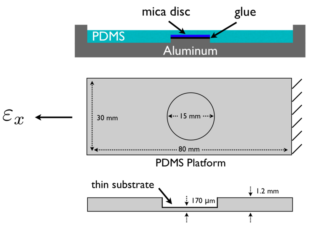
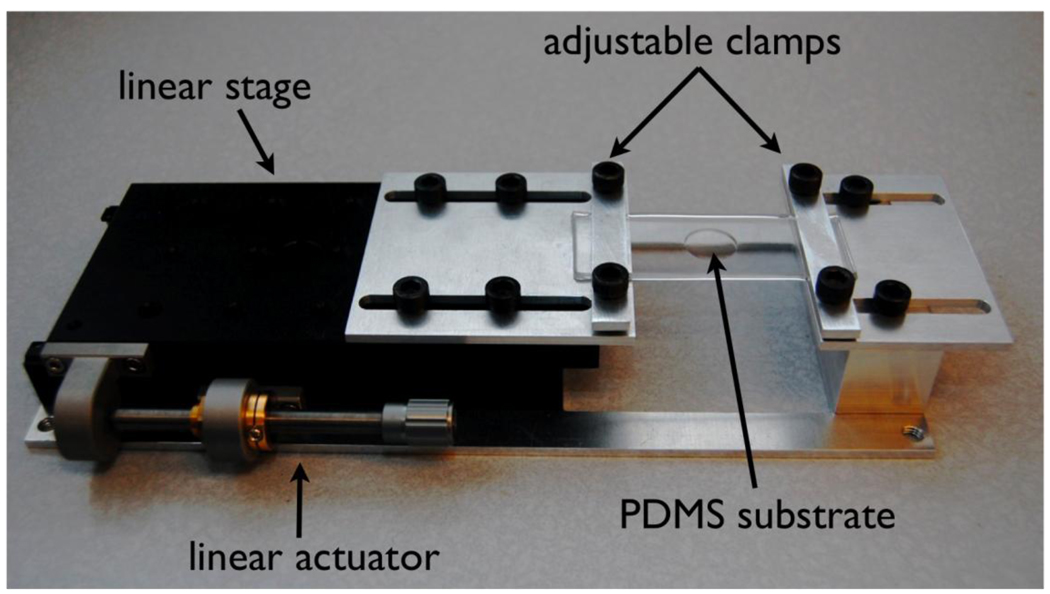
Our novel platform is a polydimethylsiloxane (PDMS) substrate with two thicknesses. A thin region (diameter = 15 mm, and thickness = 170 µm) serves as the culture surface and is surrounded by a thicker region (thickness = 1.2 mm) as shown in Figure 1. The thick substrate around the thin region provides structural support necessary for handling. The ends of the thick substrate are clamped and stretched and the strain is transferred to the thin culture surface (Figure 2). The PDMS substrate is supported by a linear stage and actuator (Newport Inc.) mounted on an aluminum base with adjustable clamps. Aluminum was chosen for its corrosion resistance in cell culture/incubator environments. Uniaxial stretch of the flexible substrate, which is unconstrained in the lateral direction, results in a Poisson’s contraction.
Figure 1.
Schematic diagrams of the aluminum mold and the flexible PDMS substrate.
Figure 2.
The stretching system consists of a flexible PDMS substrate mounted on a linear stage with an actuator. Adjustable aluminum plates are used to clamp the substrate. The system is approximately 10 inches long.
Thus as εx is applied, there is a lateral contraction of εx= −νεy for the ideally linear elastic case (Poisson’s ratio, ν≈0.5 for PDMS). To adequately describe the material behavior under large deformations a nonlinear constitutive relation must be used which is discussed later.
Polymer Casting
PDMS substrates were prepared by thoroughly mixing a 10:1 ratio of Dow Corning Sylgard 184 silicone elastomer and curing agent resulting in a Young’s Modulus of E ≈ 1 MPa [42]. The mixture was cast in an aluminum mold and cured at 100° C for 12 hrs (Figure 1). The surface of the aluminum mold was coated with a thin layer of polytetrafluoroethylene (PTFE) prior to polymer casting to facilitate mold release.
Surface Roughness
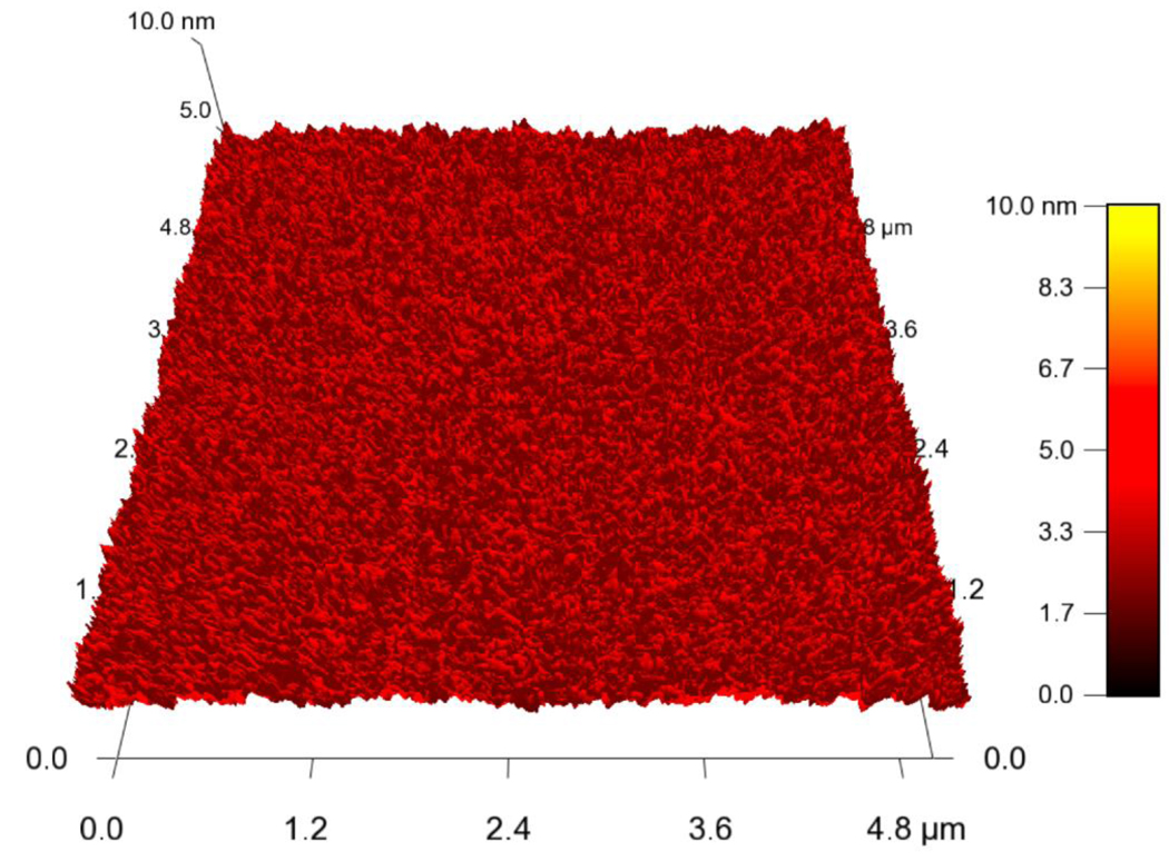
The surface of the culture reservoir is the mirror image of the surface of the polished aluminum mold. Thus, to ensure a smooth surface finish, the mold was polished with alumina nanoparticles and metal polish. The surface roughness of the resulting PDMS substrate was found to have an rms value of approximately 30 nm by atomic force microscopy (AFM). To achieve a smoother finish Mica discs were adhered to the surface of the aluminum mold and the PDMS was cured in contact with this surface as shown in Figure 1. The resulting surface roughness of the PDMS was found to have an rms value of less than 2 nm. The surface of the culture well was probed by AFM after plasma treatment and no irregular surface patterns were observed as shown in Figure 3.
Figure 3.
Surface roughness of the PDMS surface was measured by AFM after O2 plasma treatment and was found to be less than 2 nm.
Surface functionalization
PDMS can be functionalized in a variety of ways [43, 44, 45]. Here, we employed two different types of surface functionalization, using (1) silane for Drosophila embryos and (2) fibronectin for cell adhesion. (1) The silane based functionalization [46] involves a pretreatment with O2 plasma (300 W, 500 mtorr, 3 min) followed by immediate incubation in 10% (3-Aminopropyl)triethoxysilane (APTES) for two hours. After incubation, the PDMS surface was washed with phosphate buffered saline (PBS) and allowed to air dry to make the surface hydrophobic [47]. (2) A fibronectin functionalization [48] involves sterilization of the PDMS substrates with ethanol and rinsing with PBS. The substrates were then exposed to low intensity ultraviolet (UV) light for 20 minutes to ensure sterilization and modify the surface [49]. Subsequently, the culture surface of the substrate was incubated in 0.5 mL of 50 µg/mL human derived fibronectin for at least two hours to allow uniform adsorption.
3 Characterization of Substrate Deformation
When studying the effect of mechanical strain on cells and tissues quantitatively, it is important to know the magnitude and the type of strain being applied. If the strain is applied by culturing the cell or the tissue on a stretchable substrate, then the substrate strain must be known at any point on the surface. In case the substrate strain is non-uniform, then, to determine the strain on the cell, the location of the cell with respect to a reference must also be known. The latter is non trivial when observing a cell that is orders of magnitude smaller than the substrate size. A non-uniform strain field also induces a strain gradient on the cell or the tissue, which may result in additional unwanted functionalities. As an example, the strain field for a circular film induced by a pressure differential is non-uniform, it varies radially [30]. A uniform strain field of the substrate is thus most desirable, which ensures that any cell or a tissue is subjected to a prescribed strain that is independent of their location. Such uniformity is particularly important when the applied strains are large and material behavior is nonlinear. In that case, small geometric non-uniformities of the substrate (due to fabrication) can result in large unaccounted variation in the strain field [50].
We investigate the substrate strain both experimentally and numerically using finite element analysis. The in-plane displacements and strains measured experimentally match well with the numerical simulation. The simulation reveals the uniformity of the strain field and the out of plane deformation of the substrate [51, 52].
3.1 Experimental observation of the strain field
To measure the strain field experimentally, markers were added to the substrate surface and stretch was applied incrementally using the stretching system. The surface was imaged using a Canon 5D Mark II Digital SLR camera with a 65 mm 1x to 5x macro lens mounted perpendicular to the substrate surface. Strains were calculated using the built in digital image correlation (DIC) function in Matlab. The DIC algorithm located multiple trackable points within each marker and tracked their displacement through sequential images. An example of the images used for the DIC analysis is shown in Figure 4. Strains were measured both at room temperature as well as at 37°C in a cell culture incubator. In the latter case, a fixed stretch was applied and strain was measured over 24 hrs later to check for any time dependent change in the strain field in the thin substrate.
Figure 4.
Images of substrate strain for DIC analysis. The DIC algorithm locates multiple trackable points within each marker and calculates their displacement through sequential images. εx denotes tensile strain in the horizontal direction and εy denotes the compressive strain in the vertical direction in the image plane. (scale bar = 5 mm)
The deformation of the PDMS substrate was found to be completely reversible and time independent even for large strains (εx > 45%). The strain field remained steady even after 24 hrs of applied stretch at elevated temperature (37°C). Thus it can be concluded that there is no slippage in the clamps and no strain redistribution in the substrate due to relaxation of higher stresses at the stress concentration regions (near the edges of the circular thin substrate). The lack of relaxation is an important observation for two reasons: (1) this is highly desirable for controlled experiments and (2) a time independent material model can be used for the finite element analysis. The stretching system has a resolution of approximately 0.1% substrate strain.
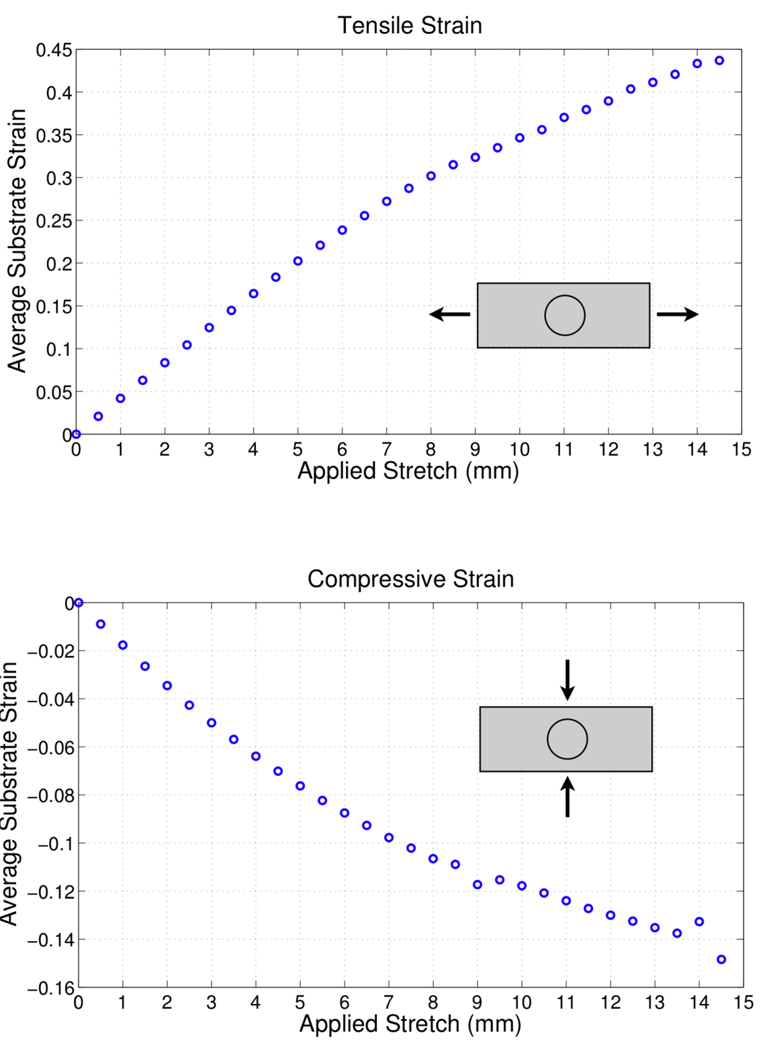
The DIC analysis yielded the experimentally observed substrate strain in Figure 5. When the substrate is stretched by 8 mm, the resulting tensile strain in the thin membrane is approximately 30% with a lateral contraction of 10%. When the substrate is stretched by 14.5 mm the resulting tensile strain is 45% with a lateral contraction of 15%.
Figure 5.
Average substrate strain as calculated by the DIC analysis. Where (a) is the tensile strain in the x direction and (b) is the compressive strain in the y direction.
3.2 Numerical Simulation of the strain field
3.2.1 Constitutive behavior of PDMS
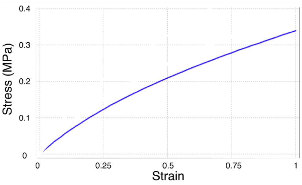
Rubber-like materials like PDMS are able to sustain large deformations with elastic recovery, and they exhibit a nonlinear stress-strain behavior (Figure 6). Here, we use the Mooney-Rivlin constitutive relation to describe the hyperelastic material behavior [53, 54, 55]. In this model PDMS is assumed to be ideally elastic, isotropic, and incompressible. The strain energy function, W, is a polynomial function of the strain invariants,
| (1) |
where cij are material constants, and I1 = trC, where C is the right Cauchy-Green deformation tensor, and the Green strain tensor is defined as [56]. For strains of less than 100%, the first order terms of the strain energy is often used which is a linear function of the strain invariants [57],
| (2) |
where c10 and c01 are the two material constants required to completely specify the material behavior, the strain invariants are, , , and the principle stretch ratios are, λi = 1+εi, where εi is the principal value of engineering strain in the ith direction. The first order Mooney-Rivlin model for a hyperelastic material was used with c10 = 90.35 kPa and c01 = 12.82 kPa which were previously reported to be valid for strains up to 50% [58].
Figure 6.
Stress-strain plot for a Mooney-Rivlin material with c10 = 90.35 kPa and c01 = 12.82 kPa used for PDMS [58].
3.2.2 Boundary conditions for numerical simulation
The PDMS substrate geometry was created in ANSYS and displacement boundary conditions were applied to the clamping area of the substrate to mimic application of strain by the stretching system. One quarter of the platform was modeled with symmetric boundary conditions: (1) all the nodes on the YZ surface were restrained against motion along the X direction, (2) all the nodes on the XZ surface were restrained against motion along the Y direction, and (3) the clamping surface was fixed in the Z direction, and an X displacement was applied to stretch the platform (refer to Figure 7 for axis orientation).
Figure 7.
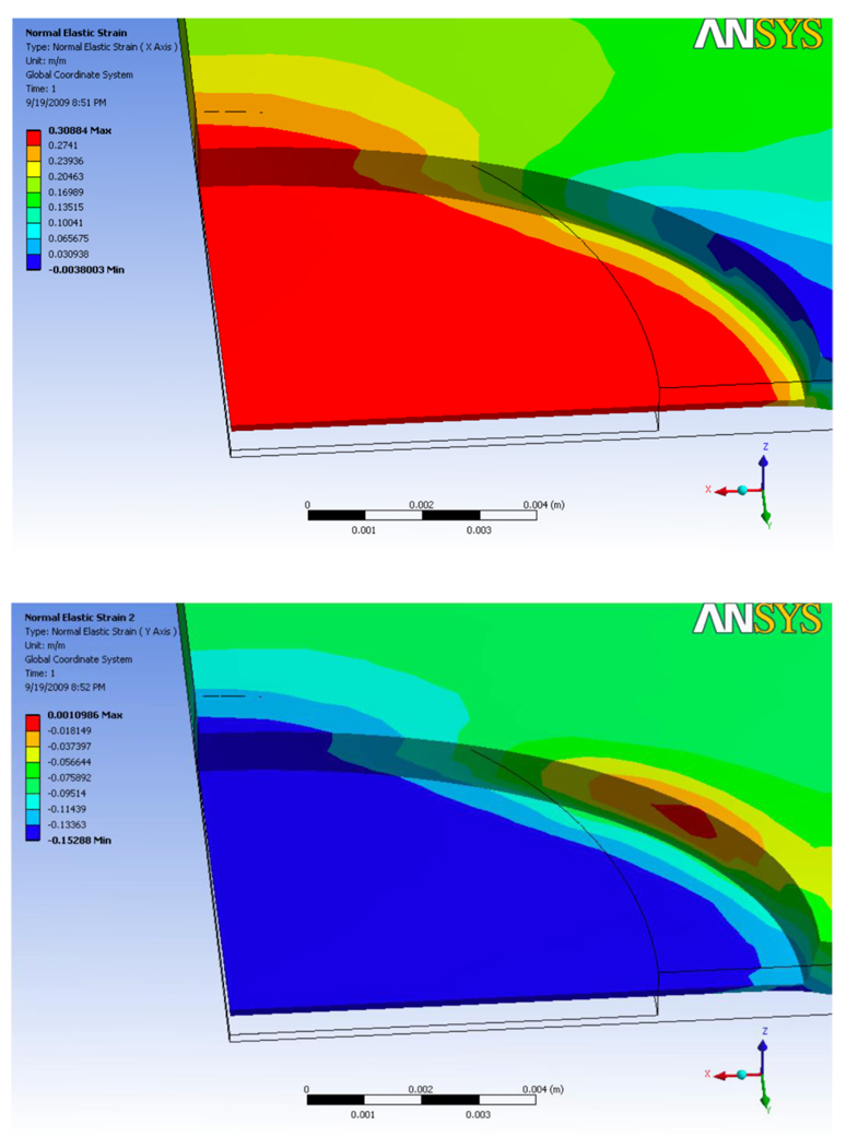
Finite element method simulation of substrate deformation using the two parameter Mooney-Rivlin hyperelastic constitutive relation. Where (a) and (b) are the contour plots of εx and εy respectively. The average predicted tensile strain and lateral contraction are εx = 30% and εy = 14% respectively.
3.3 Simulation results
3.3.1 Uniformity of strain field
Most importantly, the FEM simulation shows that the strain in the thin substrate is uniform for the majority of the surface area as seen in Figure 7. In over 95% of the surface area of the thin substrate, the surface strain varies by approximately 1%. This verifies that the strain field is uniform and any biological specimen will be under approximately the same strain regardless of its location on the substrate. This allows a highly controlled experiment where the applied strain in known regardless of the location of the specimen on the substrate.
3.3.2 Out of plane deformation
The simulation shows that at 30% tensile strain the center of the thin membrane displaces upward by 400 µm above the surrounding edge. Relative to the diameter of the membrane (15 mm) this deformation is small and the resulting membrane curvature is low and thus does not affect imaging or the uniformity of the surface strain in the thin membrane.
3.3.3 Comparison with experiment
The FEM results (Figure 7) show close agreement with the measured experimental strains (Figure 5). When an equivalent substrate stretch of 8 mm was applied in the simulation, the resulting tensile strain in the circular well along the loading direction was 30% with a lateral contraction of 14%. Thus the experimentally measured tensile strain (30% in response to 8 mm grip displacement) is in direct agreement with the results predicted by the simulation, however, the predicted value of the lateral contraction is 4% higher than observed experimentally. This deviation from experiment in the lateral contraction is expected to be a result of idealized clamping boundary conditions in the simulation in contrast to the experiment where clamping is achieved by a pair of aluminum plates held by bolts at the ends. In the experiment, after tightening the bolts, the aluminum clamps bend and the gap between the plates increases towards the center. This results in a complex state of stress in the substrate with a boundary condition that is pinching the substrate near the edges.
Biological Investigations
Our novel platform is capable of applying precise amounts of strain to cells and tissues including whole embryos while allowing in situ live imaging. To illustrate this advantage we investigated the mechanoresponse of single fibroblasts and whole Drosophila embryos.
4 Fibroblasts
Fibroblasts are a robust model system to study the basic response of the cytoskeleton to mechanical stimulus. They are the primary cells present in connective tissue and play a critical role in wound healing. Additionally they are easily cultured in vitro and have been extensively studied. Our system allows observation of real time subcellular dynamics in single cells to observe their mechanoresponse to applied strain.
Cell Culture and Transfection
Monkey kidney fibroblasts from ATCC were cultured in an incubator at 37 °C and 5% CO2 in growth medium consisting of Dulbecco’s Modified Eagle Medium (DMEM) (BioWhittaker Cat. No. 12–604F) with 10% Fetal Bovine Serum (FBS) and 1% Penicillin/Streptomycin (Pen/Strep) (Gibco). PDMS substrates were sterilized with 70% ethanol and washed with PBS. Cells were transfected with Cellular Lights Actin-GFP (Cat. No. C10126) using standard protocols from Invitrogen. After transfection, cells were trypsinized and sparsely plated on fibronectin functionalized PDMS substrates and allowed to attach for 24 hrs prior to the stretching experiment. Fibroblasts remained attached to the PDMS substrates for over 5 days indicating potential for long term stretching studies.
Microscopy and Image Analysis
To illustrate compatibility with high resolution imaging systems we observed the cytoskeletal dynamics in fibroblasts as a response to mechanical strain using a state of the art Zeiss LSM 710 NLO microscope capable of single photon and two photon laser excitation. Fluorescence and differential interference contrast images were collected simultaneously at 2 minute intervals for approximately 1 hr. The images were processed using 3-D blind deconvolution in Autoquant, and maximum intensity projection and data analysis was carried out in ImageJ [59] to measure actin fiber strain and angle change.
4.1 Dynamic rotation of intact stress fibers begins within minutes
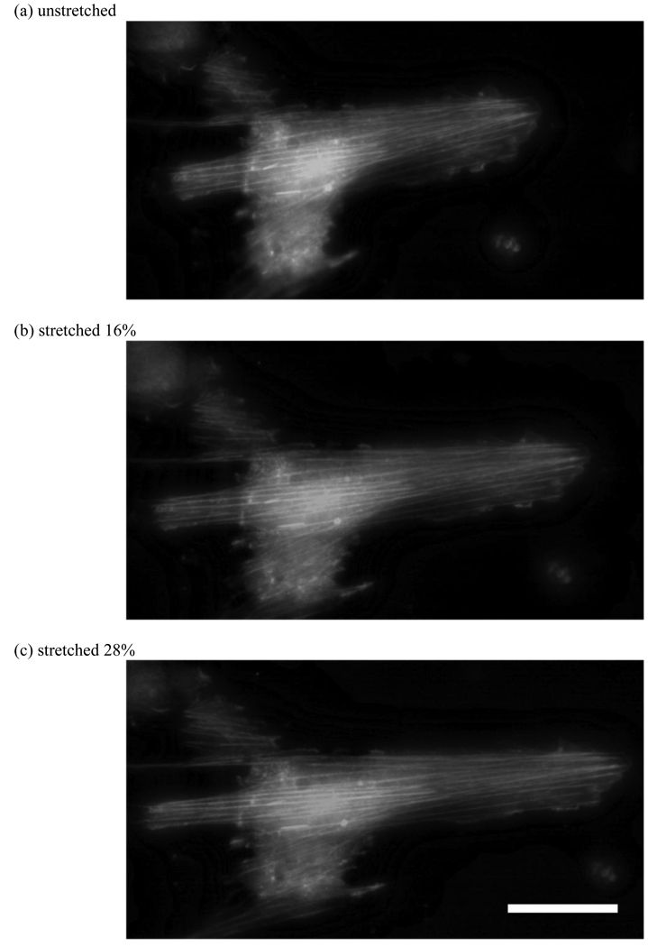
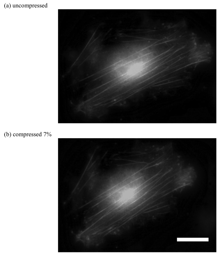
Our novel platform is capable of applying both tensile and compressive strain to the cells. To apply tensile strain, the fibroblasts were seeded on unstretched substrates and allowed to attach overnight. Then the substrates were loaded into the stretching device and stretched. The strain rate is limited by the actuator speed, and in our case the maximum strain was applied over approximately 30 seconds. The resulting substrate strain is transferred to the cell as can be seen in the GFP actin transfected fibroblasts shown in Figure 8. To apply compressive strain, the fibroblasts were seeded on prestretched substrates and allowed to attach overnight. The substrates were then unloaded, transferring a compressive strain to the cells as shown in Figure 9.
Figure 8.
Images of fibroblasts under applied tensile strain. Cells were seeded on unstretched substrate and allowed to adhere overnight and then stretched. Due to the applied strain the actin fibers are stretched axially by (b) 16% and (c) 28%. (scale bar = 30 µm)
Figure 9.
Images of fibroblasts under applied compressive strain. Cells were seeded on a prestretched substrate overnight, and the substrate was unloaded. Due to applied strain the actin fibers are compressed axially by 7%. (scale bar = 30µm)
Real time high resolution imaging allowed observation of interesting cytoskeletal dynamics including change in actin fiber angle in response to applied strain. It is known that fibroblasts reorient themselves in response to stretching, and it has been reported that cell bodies begin to show alignment within 2–3 hrs [60]. We observed that subcellular reorganization begins much earlier where actin stress fiber reorientation occurs within minutes of the applied strain. An earlier study [61], found that actin fibers in the direction of applied tensile strain depolymerized, and new actin fibers formed at an oblique angle. Also, a recent mathematical model predicts reorientation of actin stress fibers as a function of turnover (i.e., polymerization and depolymerization processes) [62]. It seems to be widely believed that actin fiber reorganization occurs mainly due to new stress fiber formation.
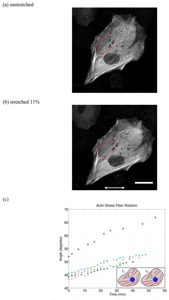
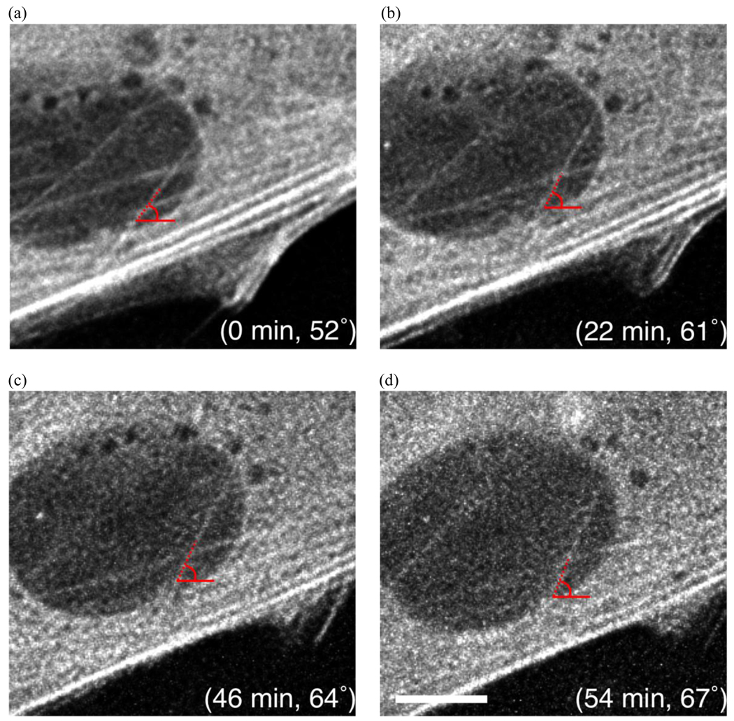
In contrast, we observed dynamic rotation of intact stable stress fibers (see supplementary video S1). In response to an applied axial strain of 11%, the actin stress fibers reoriented by rotating counter clockwise, away from the direction of applied strain (Figure 10 and Figure 11). Multiple stress fibers were measured and their rotation is plotted in Figure 10c. Thus actin fiber reorientation is not only due to fiber turnover, but intact and stable stress fibers also undergo dynamic rotation oblique to the direction of applied strain. Actin stress fibers are connected between focal adhesion complexes, which are anchored to the underlying substrate. Thus for an intact actin stress fiber to undergo dynamic rotation, it’s anchor points must move relative to each other. This observation suggests mobilization of focal adhesion complexes in response to applied strain. Interestingly, a recent study [63] found that focal adhesion sliding and actin fiber reorientation are key players in force-induced cellular reorganization independent of microtubules. This is in direct contrast to cellular reorganization during migration where microtubules are known to regulate focal adhesion dynamics [64]. These results [63] highlight the importance of in situ observation in uncovering the mechanisms of cellular mechanotransduction. It should be noted that the actin stress fibers, which underwent active dynamic rotation, extended through the center region of the cell whereas the stress fibers located at the cell periphery remained stable. This indicates that actin fiber reorganization varies spatially throughout the cell and it may be interesting to simultaneously visualize microtubules to investigate filament interaction.
Figure 10.
Actin stress fiber rotation in response to applied static strain (horizontal arrows indicate stretch direction). (a) and (b) are the original and stretched (11%) configuration respectively where the red dotted region indicates the stress fibers tracked. (c) Actin stress fiber rotation as a function of time (shown for 5 stress fibers). Here it is clear that the actin stress fiber reorientation occurs within minutes of applied strain. The small inset in the lower right schematically illustrates the stress fiber rotation where θ1 is the initial angle and θ2 is the final angle relative to the strain direction. (scale bar = 30 µm)
Figure 11.
Images of actin stress fiber rotation in response to applied strain (horizontal direction). An actin stress fiber is shown with its angle and corresponding time after applied strain. The stress fiber rotates by approximately 15° within one hour. (scale bar = 10 µm)
It is also interesting to note that multiple stress fibers originally oriented around 45° rotated by approximately the same amount (7°) away from the applied strain to 52°, whereas a stress fiber originally at 52° rotated by nearly 15° to 67° over a similar period of time. This suggests that the amount and/or rate of rotation may be a function of the initial stress fiber configuration. The mechanism for this oblique orientation of actin stress fibers is unclear. If the driving force is minimization of axial strain [65, 66] then one would expect the fibers to align to approximately 60° which is the direction of minimal strain in our substrate, as calculated from the transformation equation for plane strain,
| (3) |
where εx,εy are the normal strain in the x and y direction, γxy is the shear strain, and θ is the angle relative to the applied stretch. By setting equation (3) equal to zero and noting that γxy = 0, one can solve for θ which is the direction of zero axial strain. This may explain the rotation of stress fibers with an initial angle of approximately 45° as seen in Figure 10c. However, the stress fiber with an initial angle of 52° continues to rotate well beyond 60° and this cannot be explained by minimization of axial strain. A recent model predicts a more perpendicular orientation of the stress fiber if the cell senses stress rather than strain [67].
4.2 Lamellipodia activity and actin polymerization
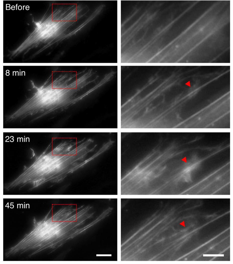
Fibroblasts were stretched inducing 10% axial strain in the actin stress fibers. After 8 minutes of applied tensile strain, we observed an abrupt onset of lamellipodia activity throughout the cell as shown in Figure 12. The lamellipodia exhibited wave-like motion emanating outward from the actin fibers. This continuing lamellipodia motion resulted in the formation of new actin stress fibers (see supplementary video S2). The propagation of actin waves may be a mechanism of cytoskeletal reorganization in response to mechanical stretching [68]. It has been shown that lamellipodial actin mechanically links myosin activity with adhesion-site formation [69]. Thus our observations of lamellipodial activity and actin polymerization in response to applied strain may suggest the formation of new adhesion sites, which is crucial to cellular motility. Assembly and disassembly of actin filaments drives cellular motility and has been shown to involve proteins such as Arp2/3, profilin, and ADF/cofilin [70, 71]. Arp2/3 complexes nucleate actin filaments, which grow from pre-existing filaments, and it has been shown to be distributed throughout actin waves [68]. Thus it is reasonable to hypothesize that Arp2/3 may be mechanically activated and is mobilized to these regions of lamellipodial activity resulting in nucleation of new actin fibers emanating from pre-existing filaments. Possible mechanisms for this mobilization are unclear and are a topic currently under investigation.
Figure 12.
Lamellipodia activity and actin polymerization induced by applied tensile strain (10% horizontal direction) was observed throughout the cell. The left column shows images of the entire fibroblast. The region within the red box is magnified and shown in the right column. The red triangle indicates an example of lamellipodia activity and actin polymerization. Lamellipodia activity begins after 8 minutes and results in new actin fiber formation by 45 minutes. (left scale bar = 30 µm)(right scale bar = 10 µm)
5 Drosophila embryos
Drosophila embryos are a convenient model system to study neurons in vivo. They have long been used to study synaptic development and neurotransmission and they are known to have structurally plastic neuromuscular junctions [72, 73]. It is believed that mechanical forces may play a role in neuronal sensing [74], and a recent in vivo study showed that mechanical tension leads to presynaptic clustering of neurotransmitters [75], although the underlying mechanisms are not well understood. Studying the role of mechanical forces in functional neurons is difficult due to experimental limitations. In vitro studies of neuronal mechanics [76, 77, 78, 79, 40, 80] use both primary and cultured cells, which lack the supporting glial cells present in in vivo systems. Our system allows mechanical stretch of the entire embryo to study the mechanoresponse of the functional neurons in their in vivo environment.
Drosophila Culture and Embryonic Dissection
Drosophila (elav’-gal4/UAS-gapGFP) embryos expressing green fluorescent protein (GFP) in all neurons were used for this investigation. Drosophila were cultured on standard grape agar plates under ambient light at 25 °C. Embryonic dissection was carried out on the silane functionalized PDMS substrates using techniques previously described by Budnik et al [81]. Briefly, the embryos were dechorionated using a 50/50 bleach and water solution for 1 minute. Embryos of the correct age (20 hrs after egg laying) were placed on double sided tape and then the PDMS reservoir was flooded with saline solution and the embryos were devitellinized. The embryos were oriented such that the ventral nerve cord was closest to the PDMS surface and the tape was removed. Upon contact with the functionalized APTES surface the embryos stick strongly and cannot be removed without damage. Glass micro-needles were created for dissection with a Sutter Instruments laser based micropippette/fiber puller. The micro-needle was used to create a dorsal incision in the embryo, remove the guts, and lay the body walls down flat on the PDMS surface resulting in a specimen that is approximately 25 µm thick (see [81] for detailed procedure). The motor neuron axons are attached to the cell body on one end and at the neuromuscular junction at the other, thus along its length the axons are not anchored.
Microscopy and Image Analysis
The mechanoresponse of Drosophila motor axons was observed using a Zeiss SteREO Luminar.V12 microscope. Fluorescence images were acquired for 30 minutes of applied strain and 30 minutes after unloading. ImageJ [59] was used to measure the strain in individual axons by two methods: (1) The change in straight line distance between the ends of the axon (P-P strain) and (2) the change in length of the axon itself (L-strain). To consistently measure the axon lengths, the image sequences were thresholded and skeletonized and NeuronJ [82] was used to trace the axon.
5.1 Drosophila motor neuron axons actively contract in response to applied strain
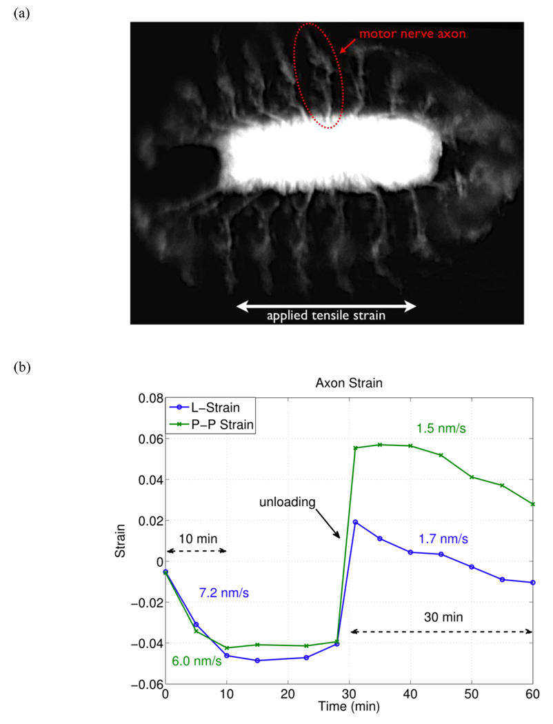
An image of a Drosophila embryo and a plot of active axonal contraction in response to the applied strain are shown in Figure 13. The embryo was oriented such that the central nervous system (CNS) is along the direction of tensile strain and the motor neuron axons of the peripheral nervous system (PNS) are along the direction of lateral Poisson’s contraction. A tensile strain of 30% was applied to the substrate resulting in a lateral compressive strain of 10%. This effectively moves the anchor points of the motor neuron axons closer together due to the Poisson’s effect in the substrate. This leaves the axons free of tension and additional shortening of axonal length over time implies an active process. Please note that compressive strains are denoted by negative numbers and tensile strains are positive numbers.
Figure 13.
Active axonal contraction was observed in response to applied strain. (a) A representative fluorescent image of the Drosophila embryo expressing GFP in all neurons. The arrow indicates a motor neuron axon. (b) Axon strain as a function of time. Here we observe axonal contraction twice, (1) after initial applied strain and (2) after substrate unloading. L-strain is the change in length of the axon, and P-P strain is the change in distance between the axon end points.
Immediately after the applied strain, the axon became more “zig-zagged” and exhibited compressive strain (decrease in length) of −5.9% relative to its original in vivo length. In this state it is assumed that the axon is in a stress free state since it is slack. Due to slight delay between applied stretch and the first image, this value was calculated by extrapolating the time-strain relation (one minute before the first image).
Over the next ten minutes the axon exhibited an active contraction to a strain of −4.6% relative to its stress free state at an average rate of 7.2 nm/s as seen in Figure 13b. After this period of active contraction, the axon’s length reached a steady state of approximately −4.9% strain. During this time the end-to-end axon strain (P-P strain) exhibited similar behavior. After a total duration of 30 minutes the substrate was unloaded (returned to zero strain) and the axons were effectively put under tension since they had contracted. As labeled by “unloading” in Figure 13b, the end points of the axon follow the substrate strain almost exactly. After unloading, the axon length was observed to have a tensile strain of 1.9%, relative to its stress free state, and it actively contracted to a compressive strain of −1.0% over the next 30 minutes at an average rate of 1.7 nm/s. It is worth noting that the average rate of axonal contraction is higher when measured along the length of the axon (L-strain) compared to measuring the distance between the end points of the axon (P-P strain). This suggests that during active contraction the axons may be building tension. (See supplementary videos S3 and S4)
We believe the active axonal contraction observed in the motor neurons of the Drosophila embryos is a response to the applied mechanical strain. Axonal contraction is observed twice: (1) after applied strain and (2) after the substrate is unloaded as shown in Figure 13b. One possible mechanism for the observed contraction could be explained by the maintenance of an internal tension within the axon, which may be involved in axonal development [83] or synaptic plasticity [75].
6 Conclusion
We have designed and characterized a novel platform to investigate the response of cells and tissues to applied strain. Our system is capable of applying prescribed uniform strain over a large substrate area for cell or tissue culture while allowing in situ observation by high resolution live imaging techniques. As a demonstration of our system we examined the mechanoresponse of single fibroblasts and whole Drosophila embryos under applied strain. In situ live imaging allowed three interesting observations: (1) Intact actin stress fibers in fibroblasts underwent dynamic rotation away from the direction of applied strain without depolymerizing. This may suggest mobilization of focal adhesion complexes in response to applied strain. (2) Lamellipodia activity and actin polymerization was induced by applied strain and resulted in new stress fiber formation in fibroblasts, suggesting mechanical mobilization of actin filament assembly proteins such as Arp2/3. (3) In Drosophila embryos, in vivo motor neuron axons exhibited active contraction in response to applied strain, possibly in an attempt to maintain a steady state internal tension necessary for neurotransmission. Our observations show the utility of our system and the importance of in situ observation during applied strain to investigate the mechanoresponse in biological systems.
Supplementary Material
Acknowledgments
The authors would like to thank X. Tang and A. Tofangchi for help with experiments, Prof. Akira Chiba for his gift of Drosophila embryos, the Institute for Genomic Biology (IGB) for use of their microscopy facilities, and the Micro-Nano Technology Laboratory (MNTL) for use of their microfabrication facilities. This work was supported by NSF CMMI 08-00870, NSF ECCS 05-24675, NSF ECCS 08-01928, and NIH 5R01NS063405-02.
Footnotes
Publisher's Disclaimer: This is a PDF file of an unedited manuscript that has been accepted for publication. As a service to our customers we are providing this early version of the manuscript. The manuscript will undergo copyediting, typesetting, and review of the resulting proof before it is published in its final citable form. Please note that during the production process errors may be discovered which could affect the content, and all legal disclaimers that apply to the journal pertain.
References
- 1.Pelham RJ, Wang YL. Cell locomotion and focal adhesions are regulated by substrate flexibility. Proc Natl Acad Sci USA. 1997 Dec;94(25):13661–13665. doi: 10.1073/pnas.94.25.13661. [DOI] [PMC free article] [PubMed] [Google Scholar]
- 2.Hasegawa S, Sato S, Saito S, Suzuki Y, Brunette DM. Mechanical stretching increases the number of cultured bone cells synthesizing dna and alters their pattern of protein synthesis. Calcif Tissue Int. 1985 Jul;37(4):431–436. doi: 10.1007/BF02553714. [DOI] [PubMed] [Google Scholar]
- 3.Engler Adam J, Sen S, Lee Sweeney H, Discher Dennis E. Matrix elasticity directs stem cell lineage specification. Cell. 2006 Aug;126(4):677–689. doi: 10.1016/j.cell.2006.06.044. [DOI] [PubMed] [Google Scholar]
- 4.Cheng W, Li B, Kajstura J, Li P, Wolin MS, Sonnenblick EH, Hintze TH, Olivetti G, Anversa P. Stretch-induced programmed myocyte cell death. J Clin Invest. 1995;96(5):2247. doi: 10.1172/JCI118280. [DOI] [PMC free article] [PubMed] [Google Scholar]
- 5.Jaalouk Diana E, Lammerding Jan. Mechanotransduction gone awry. Nat Rev Mol Cell Biol. 2009 Jan;10(1):63–73. doi: 10.1038/nrm2597. [DOI] [PMC free article] [PubMed] [Google Scholar]
- 6.Suresh Subra, Spatz Joachim P, Mills JP, Micoulet Alexandre, Dao M, Lim CT, Beil M, Seufferlein T. Connections between single-cell biomechanics and human disease states: gastrointestinal cancer and malaria. Acta Biomaterialia. 2005 Jan;1(1):15–30. doi: 10.1016/j.actbio.2004.09.001. [DOI] [PubMed] [Google Scholar]
- 7.Butcher DT, Alliston T, Weaver VM. A tense situation: forcing tumour progression. Nat Rev Cancer. 2009;9(2):108–122. doi: 10.1038/nrc2544. [DOI] [PMC free article] [PubMed] [Google Scholar]
- 8.Furchgott RF, Vanhoutte PM. Endothelium-derived relaxing and contracting factors. The FASEB Journal. 1989;3(9):2007–2018. [PubMed] [Google Scholar]
- 9.Huxley AF, Simmons RM. Proposed mechanism of force generation in striated muscle. Nature. 1971 Oct;233(5321):533–538. doi: 10.1038/233533a0. [DOI] [PubMed] [Google Scholar]
- 10.Wirtz HR, Dobbs LG. Calcium mobilization and exocytosis after one mechanical stretch of lung epithelial cells. Science. 1990;250(4985):1266–1269. doi: 10.1126/science.2173861. [DOI] [PubMed] [Google Scholar]
- 11.Wozniak Michele A, Chen Christopher S. Mechanotransduction in development: a growing role for contractility. Nat Rev Mol Cell Biol. 2009 Jan;10(1):34–43. doi: 10.1038/nrm2592. [DOI] [PMC free article] [PubMed] [Google Scholar]
- 12.Wang Ning, Tytell Jessica D, Ingber Donald E. Mechanotransduction at a distance: mechanically coupling the extracellular matrix with the nucleus. Nat Rev Mol Cell Biol. 2009 Jan;10(1):75–82. doi: 10.1038/nrm2594. [DOI] [PubMed] [Google Scholar]
- 13.Trepat X, Wasserman M, Angelini T, Millet E. Physical forces during collective cell migration. Nat Phys. 2009 Jan [Google Scholar]
- 14.Gorfinkiel N, Blanchard G, Adams R. Mechanical control of global cell behaviour during dorsal closure in drosophila. Development. 2009 Jan; doi: 10.1242/dev.030866. [DOI] [PMC free article] [PubMed] [Google Scholar]
- 15.Lecuit Thomas. "developmental mechanics": cellular patterns controlled by adhesion, cortical tension and cell division. HFSP J. 2008 Apr;2(2):72–78. doi: 10.2976/1.2896332. [DOI] [PMC free article] [PubMed] [Google Scholar]
- 16.Rauzi Matteo, Verant Pascale, Lecuit Thomas, Lenne Pierre-François. Nature and anisotropy of cortical forces orienting drosophila tissue morphogenesis. Nat Cell Biol. 2008 Dec;10(12):1401–1410. doi: 10.1038/ncb1798. [DOI] [PubMed] [Google Scholar]
- 17.Martin A, Kaschube M, Wieschaus E. Pulsed contractions of an actin-myosin network drive apical constriction. Nature. 2008 Nov; doi: 10.1038/nature07522. [DOI] [PMC free article] [PubMed] [Google Scholar]
- 18.Wang Yingxiao, Shyy John Y-J, Chien Shu. Fluorescence proteins, live-cell imaging, and mechanobiology: seeing is believing. Annu. Rev. Biomed. Eng. 2008 Jan;10:1–38. doi: 10.1146/annurev.bioeng.010308.161731. [DOI] [PubMed] [Google Scholar]
- 19.Conchello José-Angel, Lichtman Jeff W. Optical sectioning microscopy. Nat Meth. 2005 Dec;2(12):920–931. doi: 10.1038/nmeth815. [DOI] [PubMed] [Google Scholar]
- 20.Fernández-Suárez Marta, Ting Alice Y. Fluorescent probes for super-resolution imaging in living cells. Nat Rev Mol Cell Biol. 2008 Dec;9(12):929–943. doi: 10.1038/nrm2531. [DOI] [PubMed] [Google Scholar]
- 21.Giannone G, Sheetz Michael. Substrate rigidity and force define form through tyrosine phosphatase and kinase pathways. Trends in Cell Biology. 2006 Apr;16(4):213–223. doi: 10.1016/j.tcb.2006.02.005. [DOI] [PubMed] [Google Scholar]
- 22.Janmey Paul A, Weitz David A. Dealing with mechanics: mechanisms of force transduction in cells. Trends in Biochemical Sciences. 2004 Jul;29(7):364–370. doi: 10.1016/j.tibs.2004.05.003. [DOI] [PubMed] [Google Scholar]
- 23.Ingber Donald E. The mechanochemical basis of cell and tissue regulation. Mechanics & chemistry of biosystems : MCB. 2004 Feb;1(1):53–68. [PubMed] [Google Scholar]
- 24.Chen Christopher S, Tan John L, Joe Tie. Mechanotransduction at cell-matrix and cell-cell contacts. Annu. Rev. Biomed. Eng. 2004 Aug;6(1):275–302. doi: 10.1146/annurev.bioeng.6.040803.140040. [DOI] [PubMed] [Google Scholar]
- 25.Hornberger Troy A, Armstrong Dustin D, Koh Timothy J, Burkholder Thomas J, Esser Karyn A. Intracellular signaling specificity in response to uniaxial vs. multiaxial stretch: implications for mechanotransduction. Am J Physiol, Cell Physiol. 2005 Jan;288(1):C185–C194. doi: 10.1152/ajpcell.00207.2004. [DOI] [PubMed] [Google Scholar]
- 26.Houtchens Graham R, Foster Michael D, Desai Tejal A, Morgan Elise F, Wong Joyce Y. Combined effects of microtopography and cyclic strain on vascular smooth muscle cell orientation. Journal of Biomechanics. 2008 Jan;41(4):762–769. doi: 10.1016/j.jbiomech.2007.11.027. [DOI] [PMC free article] [PubMed] [Google Scholar]
- 27.Kurpinski Kyle, Chu Julia, Hashi Craig, Li Song. Anisotropic mechanosensing by mesenchymal stem cells. Proc Natl Acad Sci USA. 2006 Oct;103(44):16095–16100. doi: 10.1073/pnas.0604182103. [DOI] [PMC free article] [PubMed] [Google Scholar]
- 28.Isenberg Brett C, Dimilla Paul A, Walker Matthew, Kim Sooyoung, Wong Joyce Y. Vascular smooth muscle cell durotaxis depends on substrate stiffness gradient strength. Biophysical Journal. 2009 Sep;97(5):1313–1322. doi: 10.1016/j.bpj.2009.06.021. [DOI] [PMC free article] [PubMed] [Google Scholar]
- 29.Banes AJ, Gilbert JA, Taylor D, Monbureau O. A new vacuum-operated stressproviding instrument that applies static or variable duration cyclic tension or compression to cells in vitro. Journal of Cell Science. 1985 Apr;75:35–42. doi: 10.1242/jcs.75.1.35. [DOI] [PubMed] [Google Scholar]
- 30.Gilbert JA, Weinhold PS, Banes AJ, Link GW, Jones GL. Strain profiles for circular cell culture plates containing flexible surfaces employed to mechanically deform cells in vitro. Journal of Biomechanics. 1994 Aug;27(9):1169–1177. doi: 10.1016/0021-9290(94)90057-4. [DOI] [PubMed] [Google Scholar]
- 31.Takemasa T, Sugimoto K, Yamashita K. Amplitude-dependent stress fiber reorientation in early response to cyclic strain. Experimental Cell Research. 1997 Feb;230(2):407–410. doi: 10.1006/excr.1996.3428. [DOI] [PubMed] [Google Scholar]
- 32.Neidlinger-Wilke C, Grood ES, JH-C Wang, Brand RA, Claes L. Cell alignment is induced by cyclic changes in cell length: studies of cells grown in cyclically stretched substrates. J Orthop Res. 2001 Mar;19(2):286–293. doi: 10.1016/S0736-0266(00)00029-2. [DOI] [PubMed] [Google Scholar]
- 33.Sotoudeh M, Jalali S, Usami S, Shyy JY, Chien S. A strain device imposing dynamic and uniform equi-biaxial strain to cultured cells. Ann Biomed Eng. 1998 Jan;26(2):181–189. doi: 10.1114/1.88. [DOI] [PubMed] [Google Scholar]
- 34.Raeber GP, Mayer J, Hubbell JA. Part i: A novel in-vitro system for simultaneous mechanical stimulation and time-lapse microscopy in 3d. Biomech Model Mechanobiol. 2008 Jun;7(3):203–214. doi: 10.1007/s10237-007-0086-x. [DOI] [PubMed] [Google Scholar]
- 35.Hayakawa K, Hosokawa A, Yabusaki K, Obinata T. Orientation of smooth musclederived a10 cells in culture by cyclic stretching: Relationship between stress fiber rearrangement and cell reorientation. Zool Sci. 2000 Jul;17(5):617–624. doi: 10.2108/zsj.17.617. [DOI] [PubMed] [Google Scholar]
- 36.Camelliti Patrizia, Gallagher John O, Kohl Peter, Mcculloch Andrew D. Micropatterned cell cultures on elastic membranes as an in vitro model of myocardium. Nature Protocol. 2006 Jan;1(3):1379–1391. doi: 10.1038/nprot.2006.203. [DOI] [PubMed] [Google Scholar]
- 37.Gopalan Sindhu M, Flaim Chris, Bhatia Sangeeta N, Hoshijima Masahiko, Knoell Ralph, Chien Kenneth R, Omens Jeffrey H, Mcculloch Andrew D. Anisotropic stretchinduced hypertrophy in neonatal ventricular myocytes micropatterned on deformable elastomers. Biotechnol. Bioeng. 2003 Mar;81(5):578–587. doi: 10.1002/bit.10506. [DOI] [PubMed] [Google Scholar]
- 38.Jungbauer Simon, Gao Huajian, Spatz Joachim P, Kemkemer Ralf. Two characteristic regimes in frequency-dependent dynamic reorientation of fibroblasts on cyclically stretched substrates. Biophysical Journal. 2008 Oct;95(7):3470–3478. doi: 10.1529/biophysj.107.128611. [DOI] [PMC free article] [PubMed] [Google Scholar]
- 39.Waters CM, Glucksberg MR, Lautenschlager EP, Lee CW, Van Matre RM, Warp RJ, Savla U, Healy KE, Moran B, Castner DG, Bearinger JP. A system toimpose prescribed homogenous strains on cultured cells. J Appl Physiol. 2001 Oct;91(4):1600–1610. doi: 10.1152/jappl.2001.91.4.1600. [DOI] [PubMed] [Google Scholar]
- 40.Pfister BJ, Weihs TP, Betenbaugh M, Bao G. An in vitro uniaxial stretch model for axonal injury. Ann Biomed Eng. 2003 Jan;31(5):589–598. doi: 10.1114/1.1566445. [DOI] [PubMed] [Google Scholar]
- 41.Gerstmair A, Fois G, Innerbichler S, Dietl P, Felder E. A device for simultaneous live cell imaging during uni-axial mechanical strain or compression. Journal of Applied Physiology. 2009 doi: 10.1152/japplphysiol.00012.2009. page 00012.2009. [DOI] [PubMed] [Google Scholar]
- 42.Carillo Fernando, Gupta Shikha, Balooch Mehdi, Marshall Sally, Marshall Grayson W, Pruitt Lisa, Puttlitz Christian M. Nanoindentation of polydimethylsiloxane elastomers: Effect of crosslinking, work of adhesion, and fluid environment on elastic modulus. Journal of Materials Research. 2005;20(10):2820–2830. [Google Scholar]
- 43.Abbasi F, Mirzadeh H, Katbab AA. Modification of polysiloxane polymers for biomedical applications: a review. 2001 Jan [Google Scholar]
- 44.Ahmed Wylie W, Wolfram Tobias, Goldyn Alexandra M, Bruellhoff Kristina, Rioja Borja Aragues, Möller Martin, Spatz Joachim P, Saif Taher A, Groll Jurgen, Kemkemer Ralf. Myoblast morphology and organization on biochemically micropatterned hydrogel coatings under cyclic mechanical strain. Biomaterials. 2010 Jan;31(2):250–258. doi: 10.1016/j.biomaterials.2009.09.047. [DOI] [PubMed] [Google Scholar]
- 45.Wipff Pierre-Jean, Majd Hicham, Acharya Chitrangada, Buscemi Lara, Meister Jean-Jacques, Hinz Boris. The covalent attachment of adhesion molecules to silicone membranes for cell stretching applications. Biomaterials. 2009 Mar;30(9):1781–1789. doi: 10.1016/j.biomaterials.2008.12.022. [DOI] [PubMed] [Google Scholar]
- 46.Wu D, Zhao B, Dai Z, Qin J, Lin B. Grafting epoxy-modified hydrophilic polymers onto poly (dimethylsiloxane) microfluidic chip to resist nonspecific protein adsorption. Lab on a Chip. 2006;6(7):942–947. doi: 10.1039/b600765a. [DOI] [PubMed] [Google Scholar]
- 47.Duffy David C, Cooper McDonald J, Schueller Olivier JA, Whitesides George M. Rapid prototyping of microfluidic systems in poly(dimethylsiloxane) Anal. Chem. 1998;70(23):4974–4984. doi: 10.1021/ac980656z. [DOI] [PubMed] [Google Scholar]
- 48.Lee Jessamine Ng, Jiang Xingyu, Ryan Declan, Whitesides George M. Compatibility of mammalian cells on surfaces of poly(dimethylsiloxane) Langmuir : the ACS journal of surfaces and colloids. 2004 Dec;20(26):11684–11691. doi: 10.1021/la048562+. [DOI] [PubMed] [Google Scholar]
- 49.Efimenko K, Wallace W, Genzer J. Surface modification of sylgard-184 poly (dimethylsiloxane) networks by ultraviolet and. …. Journal of Colloid and Interface Science. 2002 Jan; doi: 10.1006/jcis.2002.8594. [DOI] [PubMed] [Google Scholar]
- 50.Friedl N, Rammerstorfer FG, Fischer FD. Buckling of stretched strips. Computers and Structures. 2000;78(1–3):185–190. [Google Scholar]
- 51.Shimizu Shigeru, Yoshida Shunya. Buckling of plates with a hole under tension. Thin-Walled Structures. 1991 Oct;12:35–49. [Google Scholar]
- 52.Shimizu S. Tension buckling of plate having a hole. Thin-Walled Structures. 2007;45(10–11):827–833. [Google Scholar]
- 53.Mooney M. A theory of large elastic deformation. Journal of Applied Physics. 1940;11:582. [Google Scholar]
- 54.Rivlin RS. Large elastic deformations of isotropic materials. i. fundamental concepts. PhilosophicalLondon Transactions of the Royal Society of Series A. Mathematical and Physical Sciences. 1948:459–490. [Google Scholar]
- 55.Rivlin RS, Saunders DW. Large elastic deformations of isotropic materials. vii. Experiments on the deformation of rubber. Philosophical Transactions of the Royal Society of London. Series A, Mathematical and Physical Sciences. 1951:251–288. [Google Scholar]
- 56.Ogden Non-linear elastic deformations. Dover Publications. 1997 Jan;:532. [Google Scholar]
- 57.Marckmann G, Verron E. Comparison of hyperelastic models for rubber-like materials. Rubber chemistry and technology. 2006 Sep;79(5):835–858. [Google Scholar]
- 58.Bellamy Kathryn, Limbert G, Waters Mark G, Middleton J. An elastomeric material for facial prostheses: synthesis, experimental and numerical testing aspects. Biomaterials. 2003 Dec;24(27):5061–5066. doi: 10.1016/s0142-9612(03)00412-5. [DOI] [PubMed] [Google Scholar]
- 59.Abramoff MD, Magalhaes PJ, Ram SJ. Image processing with imagej. Biophotonics International. 2004;11(7):36–41. [Google Scholar]
- 60.Neidlinger-Wilke C, Grood E, Claes L, Brand R. Fibroblast orientation to stretch begins within three hours. J Orthopaed Res. 2002 Jan;20(5):953–956. doi: 10.1016/S0736-0266(02)00024-4. [DOI] [PubMed] [Google Scholar]
- 61.Hayakawa K, Sato N, Obinata T. Dynamic reorientation of cultured cells and stress fibers under mechanical stress from periodic stretching. Experimental Cell Research. 2001 Aug;268(1):104–114. doi: 10.1006/excr.2001.5270. [DOI] [PubMed] [Google Scholar]
- 62.Kaunas R, Hsu HJ. A kinematic model of stretch-induced stress fiber turnover and reorientation. Journal of Theoretical Biology. 2009;257(2):320–330. doi: 10.1016/j.jtbi.2008.11.024. [DOI] [PubMed] [Google Scholar]
- 63.Goldyn Alexandra M, Rioja Borja Aragues, Spatz Joachim P, Ballestrem Christoph, Kemkemer Ralf. Force-induced cell polarisation is linked to rhoA-driven microtubule independent focal-adhesion sliding. J Cell Sci. 2009 Oct;122(Pt 20):3644–3651. doi: 10.1242/jcs.054866. [DOI] [PMC free article] [PubMed] [Google Scholar]
- 64.Small JVictor, Geiger Benjamin, Kaverina Irina, Bershadsky Alexander D. How do microtubules guide migrating cells? Nat Rev Mol Cell Biol. 2002 Nov;3(12):957–964. doi: 10.1038/nrm971. [DOI] [PubMed] [Google Scholar]
- 65.Wang JH, Goldschmidt-Clermont P, Wille J, Yin FC. Specificity of endothelial cell reorientation in response to cyclic mechanical stretching. Journal of Biomechanics. 2001 Dec;34(12):1563–1572. doi: 10.1016/s0021-9290(01)00150-6. [DOI] [PubMed] [Google Scholar]
- 66.Takemasa T, Yamaguchi T, Yamamoto Y, Sugimoto K, Yamashita K. Oblique alignment of stress fibers in cells reduces the mechanical stress in cyclically deforming fields. European Journal of Cell Biology. 1998 Oct;77(2):91–99. doi: 10.1016/S0171-9335(98)80076-9. [DOI] [PubMed] [Google Scholar]
- 67.De Rumi, Zemel Assaf, Safran Samuel A. Do cells sense stress or strain? Measurement of cellular orientation can provide a clue. Biophysical Journal. 2008 Mar;94(5):L29–L31. doi: 10.1529/biophysj.107.126060. [DOI] [PMC free article] [PubMed] [Google Scholar]
- 68.Bretschneider Till, Anderson Kurt, Ecke Mary, Muller-Taubenberger Annette, Schroth-Diez Britta, Ishikawa-Ankerhold Hellen C, Gerisch Gunther. The three-dimensional dynamics of actin waves, a model of cytoskeletal self-organization. Biophys J. 2009 Apr;96(7):2888–2900. doi: 10.1016/j.bpj.2008.12.3942. [DOI] [PMC free article] [PubMed] [Google Scholar]
- 69.Giannone G, Dubin-Thaler BJ, Rossier O, Cai Y, Chaga O, Jiang G, Beaver W, Döbereiner HG, Freund Y, Borisy G. Lamellipodial actin mechanically links myosin activity with adhesion-site formation. Cell. 2007;128(3):561–575. doi: 10.1016/j.cell.2006.12.039. [DOI] [PMC free article] [PubMed] [Google Scholar]
- 70.Pollard Thomas D, Blanchoin Laurent, Mullins RD. Molecular mechanisms controlling actin filament dynamics in nonmuscle cells. Annu. Rev. Biophys. Biomol. Struct. 2000 Jan;29:545–576. doi: 10.1146/annurev.biophys.29.1.545. [DOI] [PubMed] [Google Scholar]
- 71.Pollard Thomas D, Borisy Gary G. Cellular motility driven by assembly and disassembly of actin filaments. Cell. 2003 Feb;112(4):453–465. doi: 10.1016/s0092-8674(03)00120-x. [DOI] [PubMed] [Google Scholar]
- 72.Keshishian H, Broadie Kendal S, Chiba Akira, Bate M. The drosophila neuromuscular junction: a model system for studying synaptic development function. Annu. Rev. Neurosci. 1996 Jan;19:545–575. doi: 10.1146/annurev.ne.19.030196.002553. [DOI] [PubMed] [Google Scholar]
- 73.Sigrist Stephan J, Reiff Dierk F, Thiel Philippe R, Steinert Joern R, Schuster Christoph M. Experience-dependent strengthening of drosophila neuromuscular junctions. J Neurosci. 2003 Jul;23(16):6546–6556. doi: 10.1523/JNEUROSCI.23-16-06546.2003. [DOI] [PMC free article] [PubMed] [Google Scholar]
- 74.Chalfie Martin. Neurosensory mechanotransduction. Nat Rev Mol Cell Biol. 2009 Jan;10(1):44–52. doi: 10.1038/nrm2595. [DOI] [PubMed] [Google Scholar]
- 75.Siechen Scott, Yang Shengyuan, Chiba Akira, Saif Taher. Mechanical tension contributes to clustering of neurotransmitter vesicles at presynaptic terminals. Proc Natl Acad Sci USA. 2009 Aug;106(31):12611–12616. doi: 10.1073/pnas.0901867106. [DOI] [PMC free article] [PubMed] [Google Scholar]
- 76.Chada S, Lamoureux Phillip, Buxbaum Robert, Heidemann Steven R. Cytomechanics of neurite outgrowth from chick brain neurons. Journal of Cell Science. 1997 May;110(Pt 10):1179–1186. doi: 10.1242/jcs.110.10.1179. [DOI] [PubMed] [Google Scholar]
- 77.Cullen DKacy, LaPlaca Michelle C. Neuronal response to high rate shear deformation depends on heterogeneity of the local strain field. Journal of Neurotrauma. 2006 May;:17. doi: 10.1089/neu.2006.23.1304. [DOI] [PubMed] [Google Scholar]
- 78.Dennerll TJ, Lamoureux Phillip, Buxbaum Robert, Heidemann Steven R. The cytomechanics of axonal elongation and retraction. The Journal of Cell Biology. 1989 Dec;109(6 Pt 1):3073–3083. doi: 10.1083/jcb.109.6.3073. [DOI] [PMC free article] [PubMed] [Google Scholar]
- 79.Heidemann Steven R, Lamoureux Phillip, Buxbaum Robert. Growth cone behavior and production of traction force. The Journal of Cell Biology. 1990 Nov;111(5 Pt 1):1949–1957. doi: 10.1083/jcb.111.5.1949. [DOI] [PMC free article] [PubMed] [Google Scholar]
- 80.Smith DH, Wolf JA, Meaney David F. A new strategy to produce sustained growth of central nervous system axons: continuous mechanical tension. Tissue Eng. 2001 Apr;7(2):131–139. doi: 10.1089/107632701300062714. [DOI] [PubMed] [Google Scholar]
- 81.Budnik Vivian, Gorczyca Michael, Prokop Andreas. Selected methods for the anatomical study of drosophila embryonic and larval neuromuscular junctions. Int Rev Neurobiol. 2006 Jan;75:323–365. doi: 10.1016/S0074-7742(06)75015-2. [DOI] [PubMed] [Google Scholar]
- 82.Meijering E, Jacob M, Sarria JCF, Steiner P, Hirling H, Unser M. Design and validation of a tool for neurite tracing and analysis in fluorescence microscopy images. Cytometry A. 2004 Apr;58(2):167–176. doi: 10.1002/cyto.a.20022. [DOI] [PubMed] [Google Scholar]
- 83.Kim Yujin, Chang Sunghoe. Modulation of actomyosin contractility by myosin light chain phosphorylation/dephosphorylation through rho gtpases signaling specifies axon formation in neurons. Biochemical and Biophysical Research Communications. 2004 May;318(2):579–587. doi: 10.1016/j.bbrc.2004.04.068. [DOI] [PubMed] [Google Scholar]
Associated Data
This section collects any data citations, data availability statements, or supplementary materials included in this article.


