

Abstract
A localized long-period fiber grating emerges in a silica optical fiber transmitting femtosecond pulse-induced supercontinuum. Simultaneously, a specific higher-order fiber cladding mode associated with the grating gains amplification at the expense of the fiber core mode. The grating has a period dependent on the dielectric structure of the fiber and is therefore classified as a self-organized structure.
Despite the increasing popularity of the supercontinuum (SC) generated from optical fibers [1], the long-term stability and optical effects of such source remain relatively unknown. Here we observe that SC-generating optical fibers tend to induce long-period fiber gratings (LPFGs) that upon formation will modify the incident light field and the SC output. While this effect may be undesirable for fiber-based SC applications, it offers a novel method to fabricate the LPFGs useful for applications such as fiber sensing [2].
Our experiments involved pumping UHNA3 fiber (Nufern, East Granby, Conn.) with 80 MHz, 820 nm femtosecond pulses for SC generation [3]. The entrance end of an irradiated fiber (~1 m) developed a ~10 mm long waveguide exhibiting the expected 15–70% transmission loss across the 700–925 nm range [4]. The fiber was then reversed so that its cleaved exiting end was used for light coupling, while the end containing the waveguide became the exit (Fig. 1). Such rearrangement aimed to examine the cladding mode(s) into which the waveguide scatters away the core mode [4]. The cladding mode(s) should mostly exit from the reversed fiber without the loss occurring to the original arrangement. Indeed, the coupling efficiency (CE) of cw probe light (produced by the cw operation of the writing laser) for the reversed irradiated fiber was maximized at about 80% across the 700–925 nm range, just like a pristine (control) UHNA3 fiber (~1 m), which has no waveguide in its cleaved exit end (Fig. 1). The CE was measured to be the ratio of the maximized power exiting from the fiber to the power incident on the aspheric lens (Fig. 1). However, the far-field pattern of the exiting beam at a visible probe wavelength of 710 nm differed dramatically between the two. While the Gaussian-like pattern of the core mode is observed for the control fiber, a strong circular ring emerged from the pattern (shown as the weak background) for the irradiated fiber (Fig. 2), suggesting the presence of a higher-order cladding mode. The far-field ring was also observed at probe wavelengths across 710–860 nm. The divergence angle θ of the ring (Fig. 1) as a function of probe wavelength was measured [Fig. 3(b)].
Fig. 1.
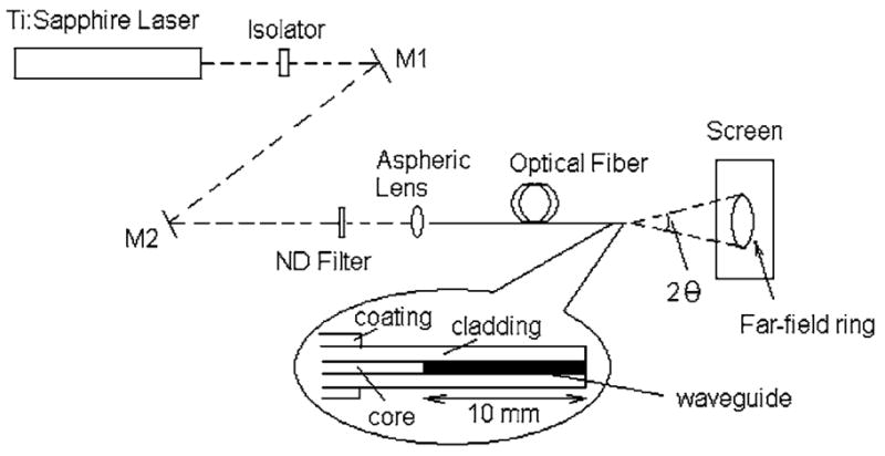
Experimental setup for in-fiber waveguide characterization.
Fig. 2.

Observed far-field pattern of the exiting beam from the control UHNA3 fiber (upper left) and the irradiated UHNA3 fiber (upper right) along with the magnified image of a sector of the latter (middle) at a probe wavelength of 710 nm; (bottom) calculated far-field angular intensity distribution of v=57 cladding mode from the UHNA3 fiber at 710 nm.
Fig. 3.

Grating period Λ as a function of wavelength λ and cladding mode order v for the (a) UHNA3 fiber and (c) UHNA1 fiber; (b) observed and calculated divergence angle θ of the far-field ring as functions of the wavelength λ for the UHNA1 and UHNA3 fibers.
Femtosecond pulses at 820 nm have also written waveguides in a UHNA1 fiber (~1 m) (Nufern, East Granby, Conn.). The measurements on this fiber yield qualitatively similar results. Quantitatively, the θ of the far-field ring is smaller [Fig. 3(b)]. The above observations support the LPFG nature of the waveguide that distributes light energy from the core mode to a single copropagating cladding mode, leading to the emergence of a single far-field ring. It is then somewhat surprising that the LPFG incurs a broadband transmission loss [4] and the incident beam generates the grating with no obvious interference pattern. Nevertheless, all results can be validated by the theory of cladding mode resonance [5].
Given the refractive index data of pure silica, germanosilicate, and pure germanium oxide [6,7], the radius and Ge concentration of the step-indexed fiber core can be derived from the NA and the cutoff wavelength of the fiber (Table 1). These properties are sufficient to calculate the effective refractive index of the core mode (neco) and the vth-order cladding mode (nev) at a given wavelength λ along with their electromagnetic fields, using a three-layer model with the ambient air as the outer layer [5]. The period of the LPFG (Λ) coupling the two modes is derived from the phase-matching condition to yield Λ=λ/[neco(λ)−nev(λ)] [2], where v is an odd integer [5]. For the UHNA3 fiber, the dependence of Λ on λ and v is plotted in Fig. 3(a). If a LPFG of Λ=18.88 μm is present, the cladding mode of v=57 becomes resonant at λ=710 nm [Fig. 3(a)]. The radial intensity profile of the cladding mode in the fiber cross section can be calculated from its electromagnetic fields [5] to predict the far-field angular intensity distribution of the cladding mode [8]. This produces a single-ring shaped pattern that approximates the observed pattern and reproduces the double-ring fine structure of the far-field ring (Fig. 2). Additionally, the θ of the ring is calculated to be 9.40°, consistent with the observed value of 9.45° [Fig. 3(b)]. The calculated θ of the rings of the neighboring cladding modes are 8.80° (v=53), 9.12° (v=55), 9.64° (v=59), and 9.92° (v=61) (Fig. 2). The separations of θ among these modes are well above the measurement accuracy of 0.1°. At λ different from 710 nm, θ can be similarly calculated at a number of discrete resonant wavelengths corresponding to the cladding modes of larger v [Fig. 3(b)]. The resulting θ versus λ data are in excellent agreement with the observed data [Fig. 3(b)]. All these agreements confirm the presence of a LPFG of Λ =18.88 μm.
Table 1.
Specifications and Derived Properties of the UHNA1 and UHNA3 Fibers
| Fiber Type | UHNA1 | UHNA3 |
|---|---|---|
| NA (1.0–1.6 μm) | 0.28 | 0.35 |
| Cutoff wavelength | 1000 nm | 900 nm |
| Cladding material | Pure silica | Pure silica |
| Cladding diameter | 125 μm | 125 μm |
| Core material | Germanosilicate | Germanosilicate |
| Core Ge conc. (derived) | 19 (mol.%) | 29 (mol.%) |
| Core radius (derived) | 1.37 μm | 0.98 μm |
The same analysis has confirmed the presence of a LPFG of Λ=33.61 μm in the UHNA1 fiber [Fig. 3(c)]. The extremely short periods of these gratings lead to the high spectral density of the cladding modes [Fig. 3(a) and 3(c)] so that their attenuation bands can overlap. This explains why a broadband loss is observed in the fiber transmission spectrum [4]. However, one dominant cladding mode is resonant at a given wavelength of the broadband loss. The activation of multiple cladding modes would broaden the width of the far-field ring and disrupt its fine structure, which are not observed at 710 nm (Fig. 2) and other wavelengths.
For UHNA3 fiber, the period of LPFG is 19.23 μm (or 18.77 μm) if the resonant cladding mode is known as v=69 (or v=71) at the writing wavelength of 820 nm [Fig. 3(a)]. As a result, why the LPFG of Λ=18.88 μm is induced can be answered by showing that the cladding mode of v=69 (or v=71) is unique at the writing wavelength. This is indeed the case, as demonstrated below. The coupling constant κco-v of the vth cladding mode related to the core mode can be normalized by the induced refractive index change of the LPFG (σ) so that the normalized coupling constant (κco-v/σ) can be calculated by the dielectric structure of the fiber given in Table 1 [5]. At 820 nm, the cladding modes with the largest (κco-v/σ) are shown in Fig. 4. The maximum value is attained at v=69, termed as the dominant cladding mode, which is in striking coincidence with the resonant cladding mode of the generated LPFG at the writing wavelength. Thus the grating period can be predicted from the dielectric structure of the fiber, and the LPFG is a self-organized structure. As a verification, the dielectric structure of UHNA1 fiber results in the dominant cladding mode of v=45 at the writing wavelength of 820 nm (Fig. 4). This mode predicts a period of Λ=33.40 μm for the corresponding self-organized LPFG [Fig. 3(c)], which is in excellent agreement with the measured value of 33.61 μm.
Fig. 4.
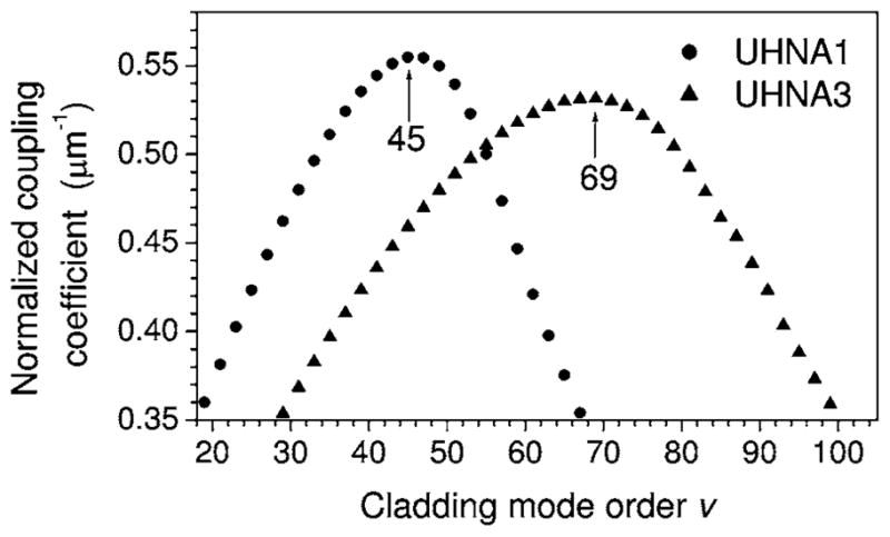
Normalized coupling constant as a function of cladding mode order v for the UHNA1 and UHNA3 fibers.
With this result in mind, the mechanism of the LPFG formation apparently resembles that of fiber Bragg grating (FBG) formation discovered in 1978 [9]. During the FBG formation, cw coherent light propagating in the fiber interferes with its weak Fresnel backreflection from the fiber end facet to produce a standing wave that through photosensitivity writes a weak index grating in the fiber core. As the strength of the grating increases the intensity of the backreflection seed grows at the cost of the forward-propagating light until a steady state is reached between the confined light and the confining glass. Similarly, during the LPFG formation, pulsed coherent light propagating in the core mode interferes with a weak copropagating light in the dominant cladding mode originated from the same source to produce the standing wave that writes a weak index grating in the fiber core. As the strength of the grating increases, the intensity of the cladding mode seed is amplified at the cost of the core mode until the steady state is reached [4]. Coupling a portion of the free-space Gaussian-mode laser beam into the cladding mode can provide the initial seed.
However, in contrast to the FBG case where only the seed in the backreflected core mode is present, in the LPFG case, multiple seeds from tens of cladding modes are present as a result of free-space-to-fiber light coupling. In one cycle of light-glass interaction during early stage LPFG formation, the interference of the core mode with the seed from the vth cladding mode strengthens the corresponding LPFG at an increasing rate with increasing seed field. The strengthened LPFG, in return, redistributes the core mode to magnify the seed field by a factor proportional to (κco-v/σ). Since the resource of the propagating core mode is limited, the competition among the cladding modes favors the growth of those having large (κco-v/σ). After many cycles of the interaction only the dominant cladding mode gains amplification, while the corresponding LPFG emerges. This mechanism implies that the LPFG formation cannot occur in bulk materials but only in wave-guiding channels. Another difference between the two cases is the localized formation of the LPFG [4], which can be attributed to the pulsed nature of the writing light. The light has a finite bandwidth (~10 nm) from which the blue and red edges write slightly different grating periods [Figs. 3(a) and 3(c)]. The superposition of the gratings from different frequency components can be in phase for a limited length, leading to the localized LPFG formation. Thus the self-organized LPFG can be generated only at the entrance end of the writing light.
The phenomenon similar to the LPFG formation has been observed from a pure silica photonic crystal fiber (PCF) [10] and another highly nonlinear PCF pumped at a largely anomalous dispersion region. This raises concern about the long-term stability of all fiber-based SC applications, regardless of the nonlinear optics of the SC generation. On the other hand, these self-written LPFGs, in certain applications, may overcome the disadvantages of those written by conventional methods. The properties of the LPFGs may be widely tuned by engineering the fiber and varying the irradiation condition.
Acknowledgments
This work was supported in part by grants from the National Institutes of Health (NIH) (NCI, 1 R21 CA115536; NIBIB, 1 R01 EB005221), the National Science Foundation (NSF) (BES 03-47747), and the Technology, Research, Education, and Commercialization Center at the University of Illinois at Urbana-Champaign.
Footnotes
OCIS codes: 060.4370, 060.3738, 190.7110.
References
- 1.Dudley JM, Genty G, Coen S. Rev Mod Phys. 2006;78:1135. [Google Scholar]
- 2.James SW, Tatam RP. Meas Sci Technol. 2003;14:R49. [Google Scholar]
- 3.Tu H, Marks DL, Koh YL, Boppart SA. Opt Lett. 2007;32:2037. doi: 10.1364/ol.32.002037. [DOI] [PubMed] [Google Scholar]
- 4.Tu H, Koh YL, Marks DL, Boppart SA. J Opt Soc Am B. 2008;25:274. doi: 10.1364/JOSAB.25.000274. [DOI] [PMC free article] [PubMed] [Google Scholar]
- 5.Erdogan T. J Opt Soc Am A. 1997;14:1760. [Google Scholar]
- 6.Nikogosyan DN. Meas Sci Technol. 2007;18:R1. [Google Scholar]
- 7.Huang AS, Arie Y, Neil CC, Hammer JM. Appl Opt. 1985;24:4404. doi: 10.1364/ao.24.004404. [DOI] [PubMed] [Google Scholar]
- 8.Ghatak A, Thyagarajan K. Introduction to Fiber Optics. Cambridge U. Press; 1998. p. 160. [Google Scholar]
- 9.Hill KO, Fujii Y, Johnson DC, Kawasaki BS. Appl Phys Lett. 1978;32:647. [Google Scholar]
- 10.Tu H, Marks DL, Jiang Z, Boppart SA. Appl Phys Lett. 2008;92:061104. doi: 10.1063/1.2857495. [DOI] [PMC free article] [PubMed] [Google Scholar]