Abstract
Optical coherence microscopy (OCM) is an interferometric technique that combines principles of confocal microscopy and optical coherence tomography (OCT) to obtain high-resolution en face images. Axial and lateral resolutions of several microns can be achieved using OCM depending on the numerical aperture (NA) of the objective and sample properties. We address the computational complexity that is inherent in spectral-domain OCM systems that limits its real-time capability as a microscope. An architecture that will improve the efficiency of the computation involved is presented. Currently, spectral-domain OCM images are obtained by individually taking the Fourier transform of each axial scan in cross-sectional frames and computationally slicing them to generate en face images. The real-time architecture presented here relies on the fact that only one Fourier domain point of a given axial scan needs to be computed rather than computing all the Fourier domain points, which can frequently require a significant amount of time to compute. This new realization has been shown to reduce the processing time to obtain the en face OCM images by a factor of 30.
Keywords: optical coherence tomography, optical coherence microscopy, en face image, numerical aperture
Optical coherence tomography (OCT) is a biomedical imaging technique that is gaining wide interest as it performs noninvasive high-resolution cross-sectional imaging of internal microstructures in materials and biological systems by measuring backscattered light. Although OCT has achieved superior resolution in comparison to many other biomedical imaging techniques such as computed tomography, magnetic resonance imaging, and ultrasound, the resolution of OCT is not always sufficient enough to view living cells (~10 µm in size). The idea of combining principles from confocal microscopy with OCT has improved the resolution of OCT to view living cells. This technique is called optical coherence microscopy (OCM).1–5 and takes advantage of very high NA (>0.9) focused illumination with spatially filtered as well as coherence-gated detection.
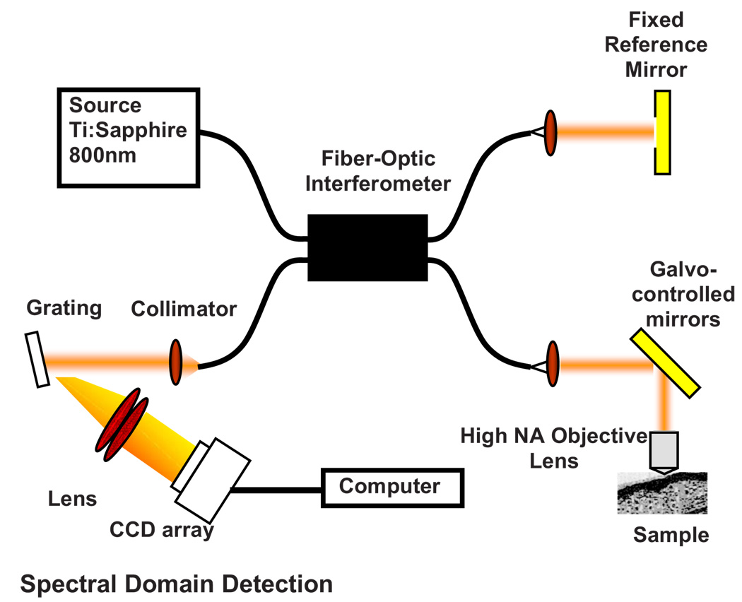
A simplified OCM system involves an interferometric setup as shown in Fig. 1. A source signal is split into two arms, namely sample and reference arms, and interfered as backscattered signals return from the two arms. High-speed instrumentation that allows en face OCM imaging has been of great interest since real-time imaging of live specimen is often desirable. A combined acquisition of optical coherence and two-photon-excited (TPE) fluorescence microscopy images was reported to have an acquisition speed of 2.8 s.2 A piezoelectric translator was used in Ref. 2 at the reference arm to displace the reference mirror, and XY raster scanning was performed using mirrors mounted on galvanometers in the sample arm. Time-domain (TD) OCM systems have been reported to have signal-to-noise ratios over 100 dB, often utilizing high-power delivery into the sample. This is not often desirable, as high powers (>10 mW) can damage the sample, particularly when using the higher NA objectives for OCM. Also, high-speed imaging can compromise the sensitivity of TD-OCM systems. High sensitivity, high-speed acquisition, and the availability of phase and spectroscopic information have directed research investigations toward spectral-domain OCM.6,7 Spectral-domain OCM systems have been reported to have sensitivity over 100 dB with only a few milliwatts at the sample.8 In spectral-domain OCM, the interfered signal is detected using a spectral-domain detection system that is comprised of a collimator, grating, and a linear CCD array. The signal, which contains depth-resolved amplitude information, is processed and displayed using a personal computer. Moreover, no movement in the reference arm is needed and galvanometer-controlled mirrors are often used to rapidly scan the beam over the sample.
Fig. 1.
Representative setup for optical coherence microscopy.
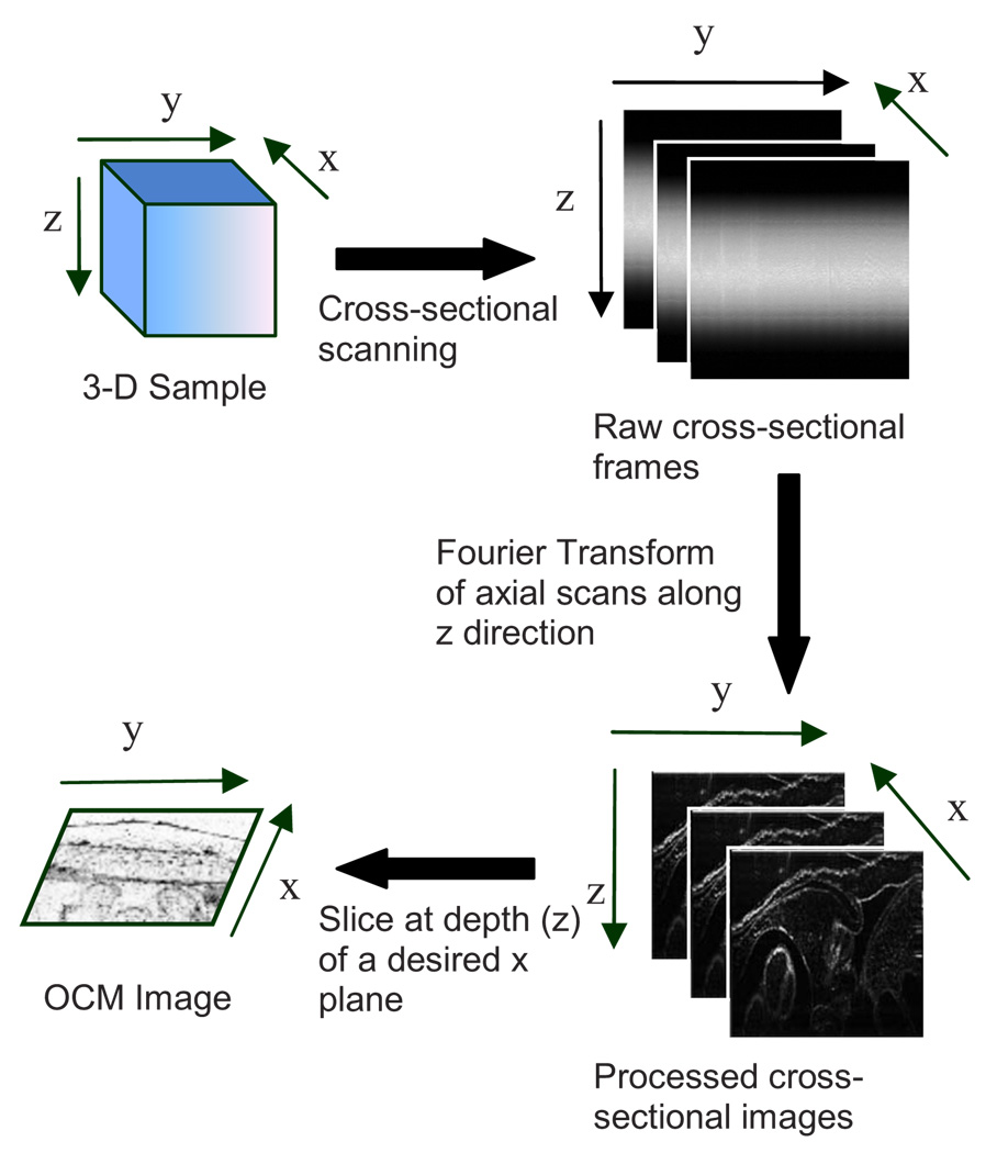
In spectral-domain OCM, as the sample is scanned, conventionally raw cross-sectional frames are first obtained. Then, a one-dimensional Fourier transform (FT) on each axial line is performed on each raw cross-sectional frame and the processed cross-sectional images are obtained. In order to obtain en face OCM images, these processed cross-sectional images are computationally sliced at the location in the images that correspond to the focal plane of the objective. Thus, the number of Fourier domain points that need to be computed to obtain the en face OCM image is very large (over a million points for a typical image). Computing a large number of Fourier domain points is therefore time-consuming and greatly impedes the real-time capability of an SD-OCM microscope. An illustration of the conventional architecture is shown in Fig. 2.
Fig. 2.
Conventional architecture to obtain en face OCM images.
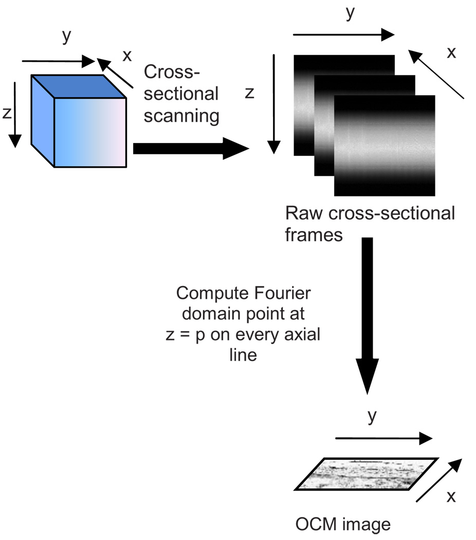
A new real-time architecture that improves the efficiency of the computation involved in obtaining the en face OCM image is needed. To address the aforementioned computational complexity in the conventional architecture, we investigated if all the Fourier domain points corresponding to an axial line need to be computed in a raw cross-sectional frame to obtain the en face OCM image. Since en face OCM imaging is at an en face plane (i.e., z=p), we demonstrate that only the one Fourier domain point at that plane [i.e., G(p)] is needed. This plane usually corresponds to the focal plane of the objective lens. The new real-time architecture is based on this idea and is illustrated schematically in Fig. 3.
Fig. 3.
Real-time architecture to obtain en face OCM images.
The discrete Fourier transform of a discrete signal s(n) of width size 2048 is given by
| (1) |
Conventionally, Fourier domain points from G(0) through G(2047) are computed for each axial line in a raw cross-sectional frame. In the real-time architecture, the Fourier domain point that corresponds to the focal plane is computed as shown in Eq. (2):
| (2) |
The exponential coefficients in Eq. (2) can be precomputed and stored rather than being computed them for each individual axial line. The primary disadvantage of using this equation and approach is that the spectral information contained within the fully acquired signal is not obtained, as all the Fourier domain points are not computed.
Due to dispersion of the light during its pass through the various optical components, the OCM signal received at the detector is skewed. That is, the frequency associated with a certain depth falls onto a pixel that is associated with a different depth on the CCD array. Therefore, the expression for G(p) should be modified using a resampling array to digitally compensate for the dispersion.9 The resampling array is given by
| (3) |
where N=axial array size (e.g., N=2048), β2=second-order dispersion, β3=third-order dispersion, ωctr=center wavelength. Therefore, Eq. (2) is modified to have the final expression
| (4) |
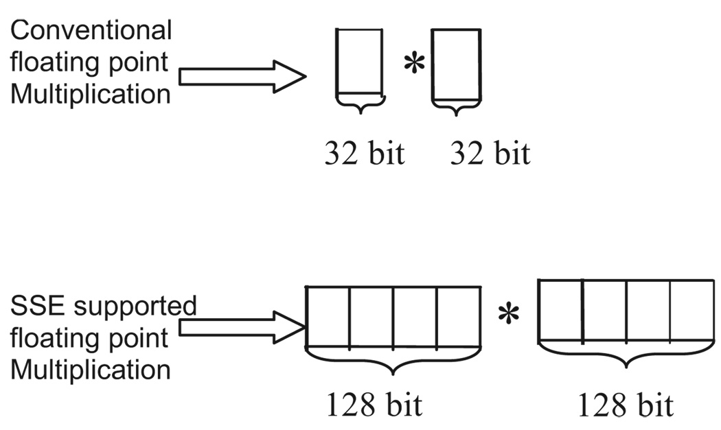
From Eq. (4), it can be seen that the processor has to perform several floating-point multiplications and additions to compute the Fourier domain point G(p). Multiplying a single pair of floating-point values significantly contributes to the complexity of this computation when real-time en face OCM images need to be displayed. For this reason, the “SSE” capability of the processors is utilized here. SSE stands for “streaming SIMD (single-instruction, multiple-data) extensions.” SSE Instructions are a set of instructions that are supported by processors such as Intel® Pentium® III, IV, etc. Using SSE, four pairs of floating-point (32-bit) values can be multiplied in a single instruction, as illustrated in Fig. 4. This feature of the processor is added in the new real-time architecture to compute the Fourier domain point G(p). This further reduces the complexity of the computation involved.
Fig. 4.
Differences between conventional and SSE multiplications.
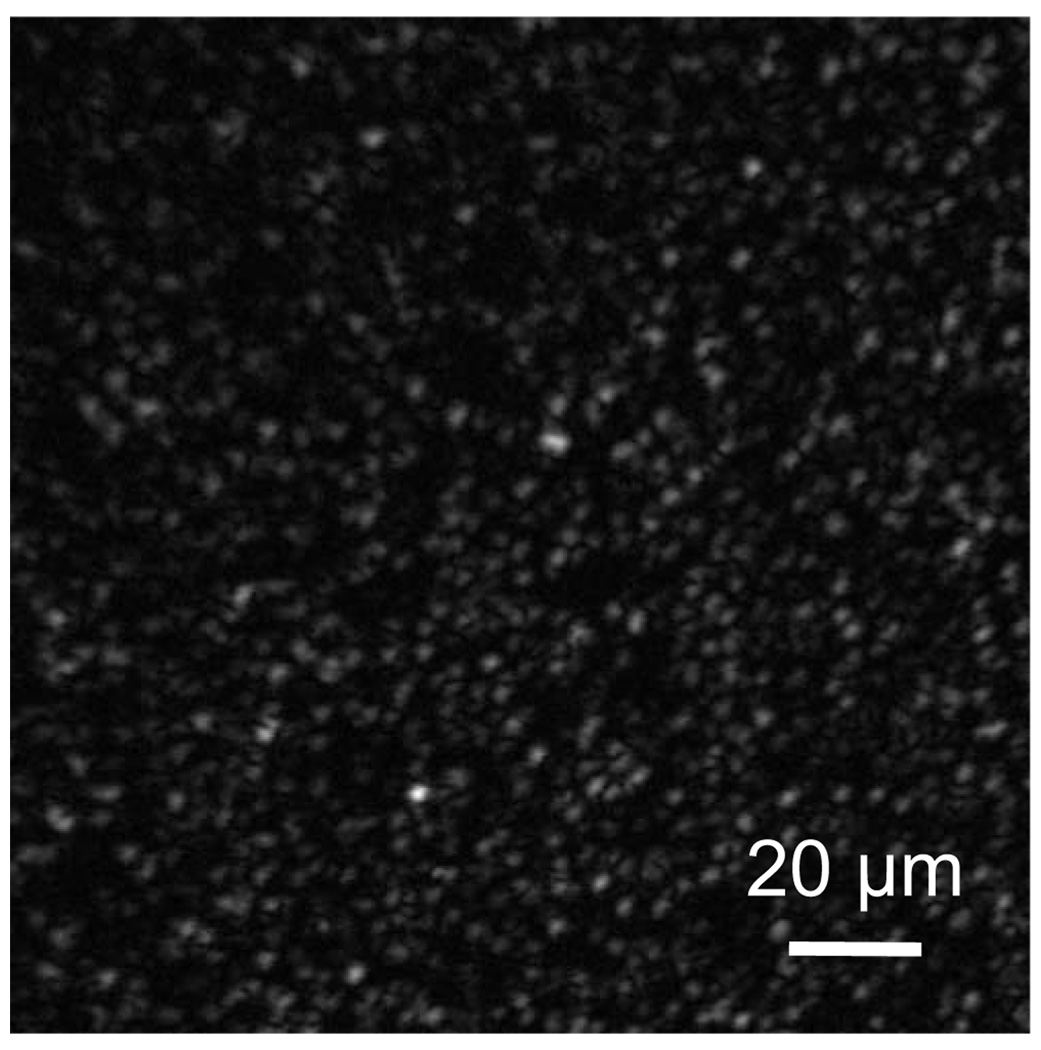
This real-time architecture was implemented on our integrated microscope that enables simultaneous acquisition of OCM and multiphoton fluorescence images.4 An en face OCM image of TiO2 particles (5-µm diameter) in silicone was acquired and is shown in Fig. 5. Computation times were measured using a 3.66-GHz Pentium® IV processor. The conventional architecture required 0.225 ms to process one pixel of a 512×512-pixel en face OCM image, corresponding to a total processing time of 59 s. Using the expression in Eq. (4), the real-time architecture required 0.0078 ms to process one pixel of a 512×512-pixel en face OCM image, corresponding to a total processing time of 2 s. Thus, there was an increase in the image processing speed by a factor of ~30.
Fig. 5.
SD-OCM image (512×512 pixels) of TiO2 particles (5-µm diameter) suspended in silicone acquired using the real-time architecture. The SD-OCM image acquired using the conventional architecture is identical to the image shown.
Since the real-time architecture uses the same reconstruction equation as the conventional architecture, except that the real-time architecture computes only one point at the focal plane, there was no reduction in the signal-to-noise ratio, contrast, or resolution. An image of the TiO2 particles captured using the conventional architecture showed no observable differences from the image shown in Fig. 5, which uses the real-time architecture. The observation made here is that not all the Fourier domain points computed in the conventional architecture contribute to the en face OCM image features. In this real-time architecture, only those Fourier domain points that actually contribute to the features of the en face OCM image are computed.
The principles of this architecture may be partially extended to spectroscopic spectral-domain OCM (SD-OCM). Spectroscopic SD-OCM analyzes the spectra as well as the intensity of the backscattered light in a depth-resolved manner. In spectroscopic SD-OCM, raw cross-sectional frames are demodulated to baseband using the fast Fourier transform (FFT) to obtain the depth-dependent signal. After windowing the confocal gate position using a Gaussian window, an inverse FFT is performed. This provides the spectral information corresponding to the confocal gate. This spectral information can be used to study absorption and scattering profiles of particles within the focal volume.10 Certain aspects of the real-time architecture presented here can be used in obtaining a real time spectroscopic OCM image. Instead of performing two FFTs as mentioned above, an infinite impulse response (IIR) filter can be applied on the raw cross-sectional frames to obtain the real-time spectroscopic SD-OCM. The application of the IIR filter on the raw cross-sectional frames can be expedited using the SSE instructions.
A real-time architecture to obtain high-speed en face SDOCM images has been presented. The real-time architecture takes into account the material dispersion introduced by the sample and compensates for this using a resampling array. Moreover, the real-time architecture takes advantage of the advanced instructions supported by the processor to improve the processing speed. These processing speed enhancements can improve real-time imaging rates when the advantages of SD-OCM are preferred over TD-OCM implementations.
Acknowledgments
This work was supported in part by the National Institutes of Health (Roadmap Initiative, 1 R21 EB005321; NIBIB, 1 R01 EB005221, S.A.B.) and the National Science Foundation (BES03-47747, BES06-19257, S.A.B.). Additional information can be found at www.biophotonics.uiuc.edu.
References
- 1.Izatt JA, Hee MR, Owen GM, Swanson EA, Fujimoto JG. Optical coherence microscopy in scattering media. Opt. Lett. 1994;19(8):590–592. doi: 10.1364/ol.19.000590. [DOI] [PubMed] [Google Scholar]
- 2.Beaurepaire E, Moreaux L, Amblard F, Mertz J. Combined scanning optical coherence and two-photon-excited fluorescence microscopy. Opt. Lett. 1999;24(14):969–971. doi: 10.1364/ol.24.000969. [DOI] [PubMed] [Google Scholar]
- 3.Dunkers JP, Cocerone MT, Washburn NR. Collinear optical coherence and confocal fluorescence microscopies for tissue engineering. Opt. Express. 2003;11(23):3074–3079. doi: 10.1364/oe.11.003074. [DOI] [PubMed] [Google Scholar]
- 4.Vinegoni C, Ralston TS, Tan W, Luo W, Marks DL, Boppart SA. Integrated structural and functional optical imaging combining spectral-domain optical coherence and multiphoton microscopy. Appl. Phys. Lett. 2006;88(5) 053901-1-3. [Google Scholar]
- 5.Tang S, Sun C-H, Krasieva TB, Chen Z, Tromberg BJ. Imaging subcellular scattering contrast by using combined optical coherence and multiphoton microscopy. Opt. Lett. 2007;32(5):503–505. doi: 10.1364/ol.32.000503. [DOI] [PMC free article] [PubMed] [Google Scholar]
- 6.Leitgeb R, Hitzenberger CK, Fercher AF. Performance of Fourier domain vs. time domain optical coherence tomography. Opt. Express. 2003;11(8):889–891. doi: 10.1364/oe.11.000889. [DOI] [PubMed] [Google Scholar]
- 7.Leitgeb RA, Drexler W, Unterhuber A, Hermann B, Bajraszewski T, Le T, Stingl A, Fercher AF. Ultrahigh resolution Fourier domain optical coherence tomography. Opt. Lett. 2004;12(10):2156–2158. doi: 10.1364/opex.12.002156. [DOI] [PubMed] [Google Scholar]
- 8.Leitgeb RA, Villiger M, Bachmann AH, Steinmann L, Lasser T. Extended focus depth for Fourier domain optical coherence microscopy. Opt. Lett. 2006;31(16):2450–2452. doi: 10.1364/ol.31.002450. [DOI] [PubMed] [Google Scholar]
- 9.Marks DL, Oldenburg AL, Reynolds JJ, Boppart SA. Autofocus algorithm for dispersion correction in optical coherence tomography. Appl. Opt. 2003;42(16):3038–3046. doi: 10.1364/ao.42.003038. [DOI] [PubMed] [Google Scholar]
- 10.Xu C, Vinegoni C, Ralston TS, Luo W, Tan W, Boppart SA. Spectroscopic spectral-domain optical coherence microscopy. Opt. Lett. 2006;31(8):1079–1081. doi: 10.1364/ol.31.001079. [DOI] [PubMed] [Google Scholar]


