Abstract
A new direction in potentiometric sensing, termed backside calibration potentiometry, was recently introduced. It makes use of the fact that the stir effect disappears in absence of ion-ionophore complex concentration gradient across supported liquid membrane ion-selective membranes. This method is especially suitable for measurements in which recalibration in the sample is not feasible, such as in remote monitoring applications. Here, a theoretical model is established to predict the working concentration range of the method. Lead(II)-selective Celgard membranes were used here with H+ as the dominant interfering ions. The emf difference for stirred and unstirred solutions was measured and the magnitude of this emf change as a function of the sample Pb2+ concentration was found to exhibit a bell shape that spans about three orders of magnitude. The concentration of interfering ions and the selectivity of the membrane were demonstrated to be important factors that affect the working range. Smaller ratios of primary ion concentrations at both aqueous sides of the membrane gave smaller emf difference values, and emf changes could still be observed with a logarithmic concentration ratio of 0.05. All experimental results correlated satisfactorily with the theoretical model.
Ion-selective electrodes (ISEs) may provide a response to the ion activity change in the aqueous phase based on changes of the phase boundary potential at the sample/membrane interface.1–4 Ionophore-based ISE membranes have been successfully developed for the detection of ions in complex samples such as undiluted whole blood.5–8 In recent years, trace analysis with ISEs has become an attractive research direction,9, 10 made possible with an improved understanding of transmembrane ion fluxes. Indeed, not only the selectivity of the ionophore but also the leaching of primary ions from the membrane to the aqueous phase boundary layer may be the limiting factor dictating the lower detection limit.11–13
Despite these important advances, potentiometric sensors still rely on the magnitude of the emf for making predictions about the sample ion activity. This implies that all other potential contributions, including that at the inner and outer reference electrode, must remain constant between the time of calibration and measurement. In routine clinical analysis of physiological samples, this time is kept short by continuously recalibrating between measurements. Moreover, careful temperature control is employed because of the influence of temperature on the electrode slope according to the Nernst equation. These procedures are not really practical in many anticipated sensing applications, such as continuous in vivo sensing,7 where intermittent recalibration is all but impossible, or in remote environmental sensing applications where human intervention is not desired. The way that potentiometric sensors have been measured has been one of the key stumbling blocks for their widespread applications outside of the controlled laboratory.
Very recently, we reported on a new concept of interrogating ion-selective membranes, termed backside calibration potentiometry.14, 15 It does not rely on the Nernst equation, which means that temperature effects or potential changes at the reference electrode are here inconsequential. The procedure evaluates the occurrence of a chemical imbalance between two sides of the ion-selective membrane by a simple stirring experiment and measuring the potential. The effect of stirring on the potential disappears if the two sides are matched in a way that eliminates transmembrane concentration gradients. The composition at the back side of the membrane is changed until the stir effect decreases to zero. Since the concentration gradients across the membrane originate from ion-exchange processes at both sides of the membrane, the concentration of the dominant interfering ion must be known or be equal at either side. This type of measurement, therefore, is sensitive to an activity ratio of two different ions, and does not allow one to perform single ion activity measurements without extrathermodynamic assumptions. These conclusions are in agreement with established thermodynamics.
The practical utility of this concept was recently demonstrated with lead-selective membranes for the determination of unknown lead(II) concentrations in a number of samples at pH 4.0, with hydrogen ions as the dominant ion-exchanging interference.15 Here, we expand the theoretical description of these devices and characterize their working characteristics in more detail. In particular, this work evaluates what concentration range can be measured, how the emf response (stir effect) changes with concentration and with the selectivity of the membrane, and how the concentration ratio at the front and back side of the membrane influences the observed emf difference. These studies are performed for the detection of lead(II) ions as an example of practical importance.
Theory
We consider here thin supported ion-selective liquid membranes containing a lipophilic ionexchanger and a selective receptor (ionophore), where steady-state concentration profiles are established in a matter of a few minutes. To simplify the theory, the level of interfering ions will assumed to be equal at both sides of the membrane and only one type of interfering ions will be considered. To describe the practical situation of lead ion sensing, primary ions are chosen to be divalent and interfering ions monovalent, but the same general approach can be applied to other systems in complete analogy.
Electrolyte co-extraction from the aqueous solution to the membrane is not considered here since the concentration of ions is relatively low. By neglecting the membrane internal diffusion potential, the membrane potential, EM can be approximated as:1, 4, 16
| (1) |
where cif and cib are the aqueous phase boundary concentrations (strictly, activities) of the primary ions I z+ on the front (f) and back (b) sides of the membrane, respectively. The two membrane phase boundary concentrations of the primary ion complex are indicated by symbols in the brackets. Equation 1 assumes that the concentration of primary ion complex is proportional to the concentration of uncomplexed ions in the membrane phase,16 which is usually valid when the complex formation constant of the ionophore is sufficiently high17 and the membrane contains excess ionophore.
It is further assumed that the level of ion-exchange at either side of the membrane will be relatively small (weak interference) so that changes in the membrane concentration have a negligible influence on the membrane potential. Instead, the membrane potential is primarily dictated by concentration changes in the contacting aqueous phase boundaries, and equation 1 is simplified to:
| (2) |
An ion exchange mechanism is assumed at both sides of the membrane and the relationship between the aqueous phase boundary concentration of primary and interfering ions can be formulated as:16
| (3) |
Where index i1 and i2 correspond to monovalent and divalent ions; and are potentiometric selectivity coefficients. This equation is written in general, both for the ions with the same or different charges. Here, we only consider the case with divalent primary ions and only one type of monovalent interfering ions so that eq 3 reduces to
| (4) |
For small levels of ion-exchange with interfering ions (less than about 10%), a less complex mixed ion response equation can be used,18 and equation 4 is simplified to:
| (5) |
Eq. 5 is rewritten for the front side of the membrane:
| (6) |
And the backside of the membrane as:
| (7) |
At steady state, the ion concentrations are usually different in each aqueous phase boundary layer at both sides of the membrane, where cifb, cibb represent the bulk solution concentrations of I 2+ at the front and back side of the membrane, respectively (Figure 1). We assume steady-state concentration profiles since supported thin liquid membranes are used.14 The relationship between steady-state ion concentrations in the membrane and aqueous phases can be written as:11, 14
| (8) |
The symbol δ is the diffusion layer thickness and D the diffusion coefficient in the indicated phases. From eq 8, the primary ion concentration gradient in the aqueous diffusion layers on both sides of the membrane must be equal:
| (9) |
If we use n as the ratio of the aqueous bulk concentrations of I2+ at the back and front side of the membrane (cibb = n cifb), eq 9 is rewritten as:
| (10) |
By inserting eqs 6, 7 and 10 into eq 8 (right most expression), we obtain:
| (11) |
With eq 11, cif can be solved from known bulk solution concentrations at either side of the membrane. The result may then be used to calculate the concentration at the inner phase boundary, cib, with eq 10. The diffusion layer thicknesses δ on both sides of the membrane are assumed to be equal because of the same stirring rate and equal geometry. The difference potential describing the stir effect is obtained by subtracting two potentials, calculated according to equation 2 with two different δaq values:
| (12) |
All other potential contributions of the measuring cell are assumed to be equal when changing the stirring rate of the sample, and thus cancel out.
Fig. 1.
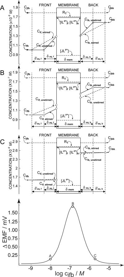
Bottom: calculated potential difference response upon changing the stirring rate at both sides of the membrane as a function of the logarithmic lead ion concentration at the back side of the membrane. The logarithmic concentration ratio of the ion at either side of the membrane is assumed as 0.2, at pH 4.0. The parameters used in the calculation were qstirred = 5.25, qunstirred = 1.57, RT = 0.005 mol/kg, and . Top: Calculated concentration profiles in the aqueous diffusion layers at the indicated positions on the response curve, at the lower limit of the detection, cifb = 10−8 M (A), the point of maximum sensitivity, cifb = 10−6.9 M (B) and the upper limit of detection cifb = 10−5.8 M (C),
EXPERIMENTAL
Reagents
Celgard 2500 microporous, flat sheet, polypropylene membranes were provided by Celgard Inc. (Charlotte, NC) and exhibited the following characteristics: 0.057 × 0.22 μm2 pore size, 25-μm thickness and 55% porosity. 4-tert-butylcalix[4]arene-tetrakis(thioacetic acid dimethylamide) (lead ionophore IV), sodium tetrakis[3,5-bis (trifluoromethyl)phenyl]-borate (NaTFPB), bis(2-ethylhexyl) sebacate (DOS), dodecyl nitrophenyl octylether (DNPOE) and tetrahydrofuran (THF) were of Selectophore grade and purchased from Fluka. Aqueous solutions were prepared with deionized water with a specific resistance of 18.2 MΩ cm. High purity HNO3 and the aqueous Pb2+ standard solution (0.1 M) were obtained from Fluka.
Membranes and Electrodes
The Pb2+-selective membranes contained lead ionophore IV (1.87 wt %, 17.74 mmol kg−1), NaTFPB (0.42 wt %, 4.58 mmol kg−1), and DOS or DNPOE (97.70 wt %). These components (totaling 149.15 mg) were dissolved in 1-mL THF. A Celgard membrane disk of 1.6-cm diameter was impregnated with this solution (38 μL) and the solvent was allowed to evaporate. The resulting membrane was immediately mounted in a plexiglass membrane holder in a symmetrical Teflon cell with an exposed area of 0.79-cm2 and two compartments of 20-mL on either side. The membrane was always freshly prepared before electrochemical characterization.
Emf Measurements
Measurements were conducted with a PCI MIO16XE data acquisition board (National instruments, Austin, TX) and a four-channel high impedance interface (WPI, Sarasota, FL) at ambient temperature (21–23 °C). Activity coefficients were obtained from the Debye-Hückel approximation, and emf values were corrected for liquid-junction potentials with the Henderson equation. The two reference electrodes used here were double-junction Ag/AgCl reference electrodes (Metrohm AG, CH-9101 Herisau, Switzerland, one with 3 M KCl and the other with 1 M KCl as reference electrolytes. Both bridge electrolytes were 1 M NH4NO3).
During measurements with Celgard-based membranes in the symmetrical Teflon cell, the solutions in both compartments were symmetrically stirred or unstirred with a magnetic stirrer. Pb2+ solutions were prepared by dilution from a 0.1 M standard solution. The solutions were adjusted to pH 4.0 or 3.0 by adding dilute HNO3. The logarithmic Pb2+ concentration ratio between the two sides of the membrane were either 0.05, 0.1 or 0.2 at the same pH from 10−4 to 10−9 M. The potential was recorded after the reading was allowed to stabilize.
Selectivity Determinations
The Pb2+-selective PVC-based membranes contained lead ionophore IV (1.85 wt %, 17.55 mmol kg−1), NaTFPB (0.41 wt %, 4.4 mmol kg−1), PVC (32.52 wt %), and DOS or DNPOE (65.22 wt %). The membranes were prepared by dissolving these components (total mass of 146.44 mg) in 1.5-mL THF. After casting this cocktail into a glass ring (2.2 cm i.d.) fixed on a glass plate, overnight evaporation of THF yielded a membrane of ~200 μm thickness. The membranes were conditioned in 10 mM HCl overnight. Then the conditioned membranes were cut with a cork borer and assembled into Philips-body electrodes. 10 mM HCl was used as the inner filling solution. The H+ calibration curve was determined before recording a Pb2+ calibration curve with the same membrane. Activity coefficients were calculated according to Meier.19
Results and Discussion
In traditional potentiometry, the observed change in the membrane potential is, ideally, directly related to the chemical driving force for ion partitioning across each of the two interfaces of the membrane.1–3, 20 For this reason, the inner solution at the back side is normally kept constant in order to obtain direct information about the ion activity at the sample side. In backside calibration potentiometry, in contrast, transmembrane ion fluxes are evaluated by observing the effect of solution stirring on the membrane potential.15 The back side composition is altered until the stir effect disappears, indicating the disappearance of a chemical driving force for ion fluxes across the membrane. In many ways, backside calibration potentiometry shares common characteristics with traditional direct potentiometry since both methods should yield information on ion activities in the contacting aqueous solutions. However, backside calibration potentiometry is expected to exhibit some unique advantages. In particular, the magnitude of the potential reading is unimportant, making this technique independent of the potential at the reference electrode. This goes at the expense of the ability to measure the activity of a single ion, since backside calibration potentiometry relies on evaluating and nullifying ion-exchange processes at both aqueous–membrane interfaces. Moreover, as the name implies, sensing membranes are interrogated and calibrated from the back side of the membrane, which may have important advantages in a number of relevant sensing situations.
The goal of the present paper is to offer improved mechanistic insights into the working principles of backside calibration potentiometry that may help develop practical applications for this interesting technique. The theory developed above calculates changes in the aqueous phase boundary concentration of the primary ion upon changing the stirring rate of both solutions. This change in local concentrations generate a change in the observed electromotive force if concentration gradients are present across the membrane.
Figure 1 evaluates the expected working range for a divalent ion-selective membrane, with a monovalent interfering ion of known concentration. In this example, the concentration ratio of primary ions at the front and back side of the membrane was kept at a fixed value (log cifb/cibb = 0.2) at pH 4.0. The parameters used in the calculation were qstirred = 5.25, qunstirred = 1.57, RT = 0.005 mol/kg, and . The selectivity coefficient was determined experimentally on traditional PVC–DOS membranes of otherwise identical composition. Evidently, changes in the lead ion concentration at the back side alters the magnitude of the stir effect, even though the concentration ratio across the membrane is kept constant.
Figure 1 suggests that a bell-shaped response curve describes the dynamic range of this measurement principle, which is found to span about 2.5 orders of magnitude using the width at the base of the curve. This behavior stands in contrast to that of direct potentiometry with ion-selective electrodes, where a log-linear dynamic range of sometimes 10 or more orders of magnitude is observed. In Figure 1, the upper and lower limit that define the dynamic range are shown at the base of the curve around 0.2 mV, which is near the practical limit of the technique as judged from our experimental experience. The calculated concentration profiles are shown for these two limits, as well as for the most sensitive part of the measurement at the peak of the curve.
The upper limit of detection is given by diminishing levels of ion-exchange at the water-membrane interfaces, see Figure 1C. Higher primary ion concentrations will show smaller levels of ion-exchange with interfering ions, reducing thereby the extent of concentration gradients in the aqueous diffusion layers. The lower limit (Figure 1A) is given by relatively large levels of ion-exchange with interfering ions. Of course, these levels are still sufficiently small as not to cause erroneous potential readings based on changes in the membrane composition: the simplification used in equation 2 still holds true. Rather, the levels of ion-exchange, dictated by the interfering ions in the sample, now approach thermodynamic control. Changes in the diffusion layer thickness have no effect on the phase boundary concentrations because they are now fully dictated by the level of ion-exchange at the interface, see also the reference.21 At the maximum stir effect shown in Figure 1B, the concentration gradients are found to proportionally change with the change in the Nernst diffusion layer thickness, yielding the largest phase boundary concentration changes.
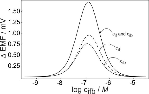
The total emf difference recorded in the experiment is a result of the sum of the potentials at the outer and inner phase boundaries. Figure 2 illustrates how the two individual phase boundary potentials change with varying concentration of divalent primary ion at the backside, again keeping the ratio of the two concentrations at the front and back of the membrane the same, as in Figure 1. The emf changes at the lower concentration end are quite similar on both sides but become slightly different when the concentrations are increased. The overall change in membrane potential as a function of the back side concentration in Figure 2 is larger than that predicted for each separate phase boundary and assumes the form of a slightly asymmetrical bell-shaped curve.
Fig. 2.
Calculated potential difference for stirred and unstirred solutions at the outer (front) and inner (back) phase boundary of the membrane, and the predicted overall membrane potential change (membrane) as a function of the backside concentration of the primary ions. All parameters as for Figure 1, calculations according to eq 12.
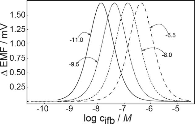
Figure 3 demonstrates how different values are expected to affect the working range, assuming all other parameters to be the same. Obviously, changes in only affect the position of the measuring range, while the magnitude of the emf change or shape of the bell curve are all expected to remain the same. A decrease of (better selectivity) will shift the working range to lower concentrations, as expected. Interestingly, changing by 1.5 orders of magnitude will shift the concentration range by only 0.5 order of magnitude. This is consistent with the expected decrease in optimal detection limit for polymeric membrane selective electrodes with increasing selectivity when ion fluxes become relevant, see equation 9 in the reference.22
Fig. 3.
Calculated emf change in stirred and unstirred solutions as a function of the back side concentration of the primary ions for different selectivity coefficients of the membrane, . Other parameters as in Figure 1.
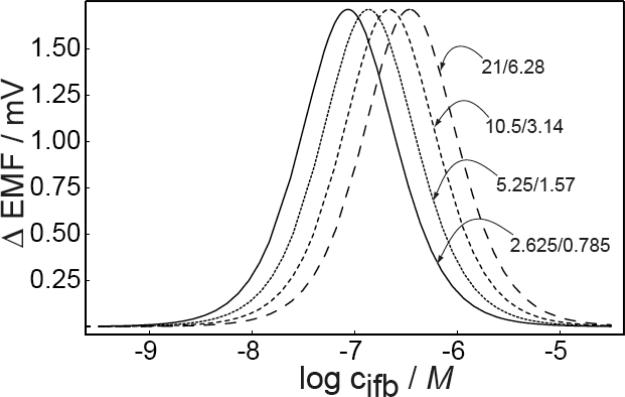
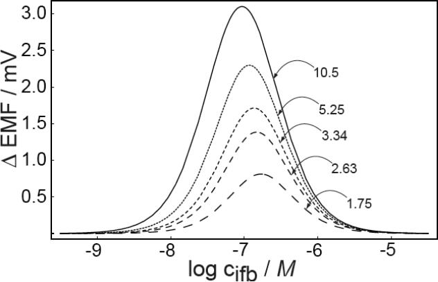
The theoretical predictions of the effect of q values (eq 8) on the response characteristics are shown in Figure 4. When the values of q are altered while keeping their ratio for stirred and unstirred solutions the same, the working range only shifts to higher or lower concentration ranges in analogy to changes in the selectivity coefficients, see Figure 4a. Figure 4b, however, shows that the a change in the ratio of q values affects the width and magnitude of the bell-shaped response curve. Consequently, the sensitivity and the working range of backside calibration potentiometry may be improved by optimizing the kinetic parameters of the experiment.
Fig. 4.
Predicted emf change in stirred and unstirred solutions as a function of A) the back side concentration of the primary ions at different values of q, keeping the ratio of q fixed at 3.34 and B) for different values of the ratio of q (for stirred and unstirred solution) at qstirred = 3.14. Other parameters as in Figure 1.
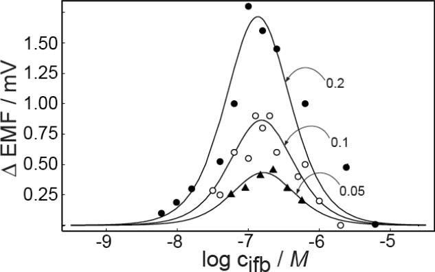
The effective working range of this method was evaluated experimentally with lead ion selective electrodes. The Pb2+ solutions were prepared at pH 4.0 with H+ as the dominant interfering ions and with a constant lead ion concentration ratio on both sides of the membrane. The potential was measured while stirring the sample until the reading was stable, assuming steady-state, and the potential was monitored upon stopping sample stirring until it was again stable. The results show that the difference of the steady-state potential in stirred and unstirred solutions changed with the primary ion concentration (with a constant difference in log ci on both sides), indeed assuming a bell-shaped curve as a function of the logarithmic concentration at the back side. Figure 5 shows the observed relationship with a logarithmic primary ion concentration difference of 0.05, 0.1 and 0.2, respectively, and theoretical expectations according to eq 12. For the logarithmic primary ion concentration difference of 0.2, the maximum emf difference in stirred and unstirred solutions was about 1.8 mV and the working range was found as 10−5.5 to 10−8.0 M (at limiting Δemf values of 0.2 mV), which is sufficiently wide for practical applications. If the primary ion concentration is outside this working range, equal emf values in stirred and unstirred solutions do not mean that no concentration gradient exists in the diffusion layers. Instead, the sensitivity of the method falls below measurable values. Here, a limiting emf difference of 0.2 mV was used, at which point it becomes difficult to distinguish the emf signal from potential drifts and noise. Clearly, the concentration limits of the technique are also influenced by instrumental parameters.
Fig. 5.
Observed (data points) and calculated (solid lines) emf difference responses in stirred and unstirred solution at different logarithmic Pb2+ concentration ratios at the front and back side of the membrane. Other parameters as for Figure 1.
In practical applications the experiments need to involve backside solutions leading to positive and negative stir effects,15 effectively bracketing the concentration of interest. This type of protocol will avoid any errors originating from disappearance of the stir effect because the primary ion concentration is outside of the working range.
The effect of the magnitude of primary ion concentration ratio at both sides of the membrane on the difference signal was explored to characterize the expected resolution of the technique. Figure 5 also shows the response behavior for logarithmic concentration ratios of 0.1 and 0.05, respectively. The magnitudes of the emf difference decrease to 0.9 and 0.45 mV for these two experimental cases. Together with the data at the logarithmic concentration ratio of 0.2, the difference signal can be stated to reduce proportionally with the logarithmic concentration ratio. The results were again in good agreement with theoretical expectations, shown as solid lines.
The emf difference is a function of the magnitude of the ion flux across the membrane, and larger concentration ratios will produce larger concentration gradients. The working range for the logarithmic concentration ratio of 0.1 and 0.05 are about 10−7.7–10−6.0 and 10−7.3–10−6.2 M (at Δemf = 0.2 mV), respectively. While the shape or width of the response curves do not appear to change, the limiting emf difference is reached at smaller deviations from the maximum value as the concentration ratio is reduced. It was previously estimated that the technique may not be able to distinguish logarithmic concentration ratios smaller than about ±0.1.15 Clearly, these earlier experiments were not performed at maximum sensitivity, but near the lower edge of the bell shaped response curve, giving a reduced resolution.
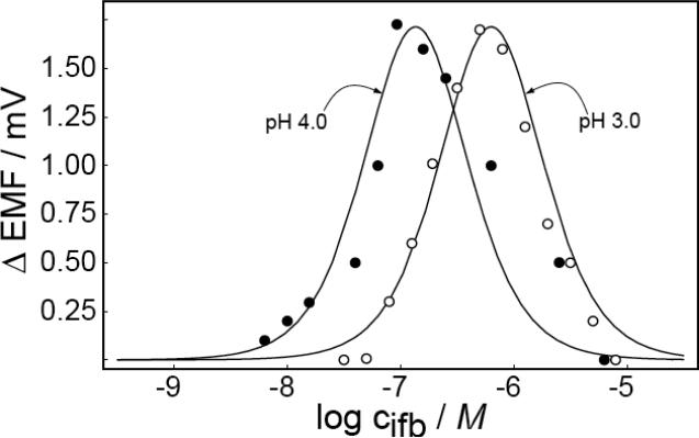
Theory predicts a clear relationship between membrane selectivity and the position of the working range. Rather than characterizing membranes with a different selectivity, which may be difficult to do without also altering other response parameters, the working range was explored at another solution pH. Specifically, the Pb2+ solutions at both sides of the membrane were adjusted to pH 3.0 with a logarithmic concentration ratio of 0.2 in the two compartments. If this shift would again correspond to that of the optimized detection limit of ion-selective membranes where ion fluxes are relevant, each order of magnitude concentration change should shift the logarithmic working range by 2/3, see eq 9 in reference.22 The results are plotted in Figure 6 for both explored pH values, 3.0 and 4.0. As expected, the shape of the curve and the magnitude of the emf change were the same in both experiments, but the working range shifted to higher concentrations (10−5.2–10−7.2 M at Δemf = 0.2 mV). This behavior agrees well with theoretical predictions, and can be explained by the extent of ion exchange at the both sides of the membrane. This experiment shows that the working range for backside calibration potentiometry is strongly dependent on the interfering ion concentration. On the other hand, the emf change for stirred and unstirred solutions is independent of the interference level if the concentration ratio on the two sides is fixed.
Fig. 6.
Observed (data points) and calculated (solid lines) emf difference responses in stirred and unstirred solutions, at pH 3.0 and 4.0. Other parameters according to Figure 1.
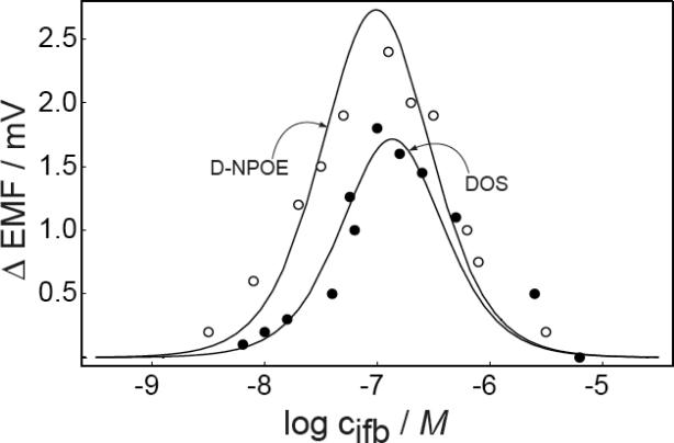
If the lower concentration of the working range is indeed dictated by the level of interfering ions, the detection limit should improve by further decreasing , which is possible by tuning the membrane composition such as by changing of the ionophore or the plasticizer. To demonstrate this effect, membranes containing the plasticizer DNPOE, rather than DOS, were prepared with otherwise the same membrane composition. Generally, membranes for divalent ions possess better selectivity over monovalent ions with NPOE-type plasticizers than with DOS.3, 5 The selectivity of membranes containing lead ionophore IV over protons was characterized with established plasticized PVC membranes since reliable selectivity characterization for Celgard membranes is not possible because of the strong transmembrane ion fluxes. According to previous work,14 the selectivity coefficients of Celgard based ISE membranes are similar to that of PVC based membranes. The membranes were conditioned with the discriminated ions, as established,23 and the calculated were found as −8.0 ± 0.1 for PVC–DOS (H+ slope = 55 ± 0.5 mV/dec, n = 3) and −9.1 ± 0.1 for PVC–DNPOE (H+ slope = 53 ± 0.1 mV/dec, n = 3). A shift of the working range to lower concentrations is therefore expected on the basis of the improved selectivity of DNPOE plasticized membrane. Indeed, Figure 7 demonstrates that the working range for Celgard membranes is shifted to a lower concentration range (10−8.5–10−5.5) with DNPOE; other parameters used for the theoretical curve: qstirred = 17.0, qunstirred = 2.26, RT = 0.005 mol/kg. The change in plasticizer not only altered the selectivity coefficient of the membrane but also the kinetics of the system since the magnitude of the emf change is increased relative to membranes containing DOS. As shown in Figure 4, the magnitude of emf change is slightly raised with a higher ratio of q in stirred and unstirred solutions. Since the membrane characteristics are not expected to change when the stirring rate is altered in the solution, the reason for the somewhat increased senstivity may be found in geometrical changes of the membrane.
Fig. 7.
Observed and calculated emf difference responses in stirred and unstirred solutions for membranes containing DOS and DNPOE, respectively. Parameters for the calculation of the DNPOE response: , qstirred = 17.0, qunstirred = 2.26, RT = 0.005 mol/kg. Parameters for the DOS membrane are as for Figure 1.
Conclusions
Backside calibration potentiometry is a new direction for potentiometric sensors, and this paper explored the parameters that may affect the sensitivity and working range of the technique by theory and experiment. The working range was demonstrated to be dependent on the primary ion concentration ratio on both sides of the membrane. The level of interfering ions affected the working range, which was shifted to higher concentrations with increased levels of interference. Each order of magnitude of concentration change appears to result in a shift of 2/3 orders of magnitude. The position of the working range was also found to be dependent on the selectivity of the membrane, which was demonstrated with different types of plasticizers. With the setup used here, logarithmic concentration ratios of 0.05 (12% concentration imbalance) between the front and back side of the membrane could be clearly distinguished from each other, with the detection limit at maximum sensitivity estimated to be around 0.02 (5%). These limiting values are a function of the quality of the electrochemical experiment and could be further improved. The technique discussed here is expected to be remarkably robust, despite the kinetic nature of the measurement, since the disappearance of the stir effect indicates the establishment of electrochemical equilibrium across the membrane. As such, the method should not suffer from chemically passive surface fouling processes that may be problematic with more kinetic methods of analysis. Similarly, any deterioration in membrane selectivity will only shift the measuring range of the technique, and not adversively affect accuracy as long as the range is not shifted outside the concentration of interest. Moreover, changes in the membrane diffusion coefficients will influence the amplitude of the bell-shaped response function, but not the sample condition where the stir effect disappears. The key limitations of the method probably lie in the required knowledge of the concentration and nature of the interfering ion, and in the need for fluidic control at the back side of the membrane. The first concern will place constraints on the variety of samples that can be measured with such a principle. Fortunately, physiological and many environmental samples contain a high and relatively constant concentration of such interfering ions. The second issue could, in principle, be solved with sensors that are configured similarly to established microdialysis probes, where the flow rate and composition of the internal solution can be precisely controlled. Alternatively, a fluidic-less system utilizing current may be envisaged to compensate for the transmembrane ion flux. Future research will evaluate these and other possibilities to aim at making this interesting new technique practically useful.
Acknowledgments
This work was financially supported by the National Institutes of Health (EB002189). W.N. thanks The Development and Promotion of Science and Technology Talent Project (DPST) and The Institute for the Promotion of Teaching Science and Technology (IPST) for a scholarship.
Literature Cited
- (1).Morf WE. The Principles of Ion-Selective Electrodes and of Membrane Transport. Elsevier; New York: 1981. [Google Scholar]
- (2).Buck RP, Lindner E. Anal. Chem. 2001;73:88A–97A. doi: 10.1021/ac012390t. [DOI] [PubMed] [Google Scholar]
- (3).Bakker E, Bühlmann P, Pretsch E. Chem. Rev. 1997;97:3083–3132. doi: 10.1021/cr940394a. [DOI] [PubMed] [Google Scholar]
- (4).Bakker E, Buhlmann P, Pretsch E. Talanta. 2004;63:3–20. doi: 10.1016/j.talanta.2003.10.006. [DOI] [PubMed] [Google Scholar]
- (5).Anker P, Ammann D, Asper R, Dohner RE, Simon W, Wieland E. Anal. Chem. 1981;53:1970–1974. doi: 10.1021/ac00236a005. [DOI] [PubMed] [Google Scholar]
- (6).Maruizumi T, Wegmann D, Suter G, Ammann D, Simon W. Mikrochim. Acta. 1986;I:331–336. [Google Scholar]
- (7).Meyerhoff ME. Trends Anal. Chem. 1993;12:257–266. [Google Scholar]
- (8).Gunaratna PC, Koch WF, Paule RC, Cormier AD, D'Orazio P, Greenberg N, O'Connell KM, Malenfant A, Okorodudu AO, Miller R. Clin. Chem. 1992;38:1459–1465. [PubMed] [Google Scholar]
- (9).Bakker E, Pretsch E. Trends Anal. Chem. 2005;24:199–207. doi: 10.1016/j.trac.2005.01.003. [DOI] [PMC free article] [PubMed] [Google Scholar]
- (10).Malon A, Vigassy T, Bakker E, Pretsch E. J. Am. Chem. Soc. 2006;128:8154–8155. doi: 10.1021/ja0625780. [DOI] [PMC free article] [PubMed] [Google Scholar]
- (11).Mathison S, Bakker E. Anal. Chem. 1998;70:303–309. [Google Scholar]
- (12).Sokalski T, Ceresa A, Zwickl T, Pretsch E. J. Am. Chem. Soc. 1997;119:11347–11348. [Google Scholar]
- (13).Szigeti Z, Vigassy T, Bakker E, Pretsch E. Electroanalysis. 2006;18:1254–1265. doi: 10.1002/elan.200603539. [DOI] [PMC free article] [PubMed] [Google Scholar]
- (14).Tompa K, Birbaum K, Malon A, Vigassy T, Bakker E, Pretsch E. Anal. Chem. 2005;77:7801–7809. doi: 10.1021/ac051362y. [DOI] [PubMed] [Google Scholar]
- (15).Malon A, Bakker E, Pretsch E. Anal. Chem. 2007;79:632–638. doi: 10.1021/ac061467g. [DOI] [PMC free article] [PubMed] [Google Scholar]
- (16).Ceresa A, Radu A, Peper S, Bakker E, Pretsch E. Anal. Chem. 2002;74:4027–4036. doi: 10.1021/ac025548y. [DOI] [PubMed] [Google Scholar]
- (17).Mi Y, Bakker E. Anal. Chem. 1999;71:5279–5287. doi: 10.1021/ac9905930. [DOI] [PubMed] [Google Scholar]
- (18).Bakker E, Meruva RK, Pretsch E, Meyerhoff ME. Anal. Chem. 1994;66:3021–3030. doi: 10.1021/ac00091a600. [DOI] [PubMed] [Google Scholar]
- (19).Meier PC. Anal. Chim. Acta. 1982;136:363–368. [Google Scholar]
- (20).Koryta J. Principles of Electrochemistry. Wiley; Chichester: 1987. [Google Scholar]
- (21).Radu A, Telting-Diaz M, Bakker E. Anal. Chem. 2003;75:6922–6931. doi: 10.1021/ac0346961. [DOI] [PubMed] [Google Scholar]
- (22).Ceresa A, Bakker E, Hattendorf B, Günther D, Pretsch E. Anal. Chem. 2001;72:343–351. doi: 10.1021/ac001034s. [DOI] [PubMed] [Google Scholar]
- (23).Bakker E. J. Electrochem. Soc. 1996;143:L83–L85. [Google Scholar]


