Abstract
In this paper, we present a novel method for texture mapping of closed surfaces. Our method is based on the technique of optimal mass transport (also known as the “earth-mover’s metric”). This is a classical problem that concerns determining the optimal way, in the sense of minimal transportation cost, of moving a pile of soil from one site to another. In our context, the resulting mapping is area preserving and minimizes angle distortion in the optimal mass sense. Indeed, we first begin with an angle-preserving mapping (which may greatly distort area) and then correct it using the mass transport procedure derived via a certain gradient flow. In order to obtain fast convergence to the optimal mapping, we incorporate a multiresolution scheme into our flow. We also use ideas from discrete exterior calculus in our computations.
Index Terms: Texture mapping, optimal mass transport, parametrization, spherical wavelets
1 INTRODUCTION
In this paper, we employ an approach for texture mapping based on the technique of optimal mass transport (OMT), also known as the “earth mover’s problem.” The original transport problem, proposed by Gaspard Monge in 1781, asks how best to move a pile of soil or rubble to an excavation or fill with the least amount of work. The problem was analyzed and given a modern formulation by the Soviet mathematician and econometrist Kantorovich [43] in the 1940s and so is known now as the Monge-Kantorovich (MK) problem. OMT has found uses in numerous fields including fluid and continuum mechanics, automatic control, statistical physics, shape optimization, expert systems, meteorology, econometrics, data compression, and image processing; see [55], [70], and the references therein.
The texture mapping methodology is based on mapping an image either synthesized or digitized onto a given surface. There is plenty of literature on this topic in the computer graphics community, e.g., see [23] and the references therein. We will not review all the literature on this subject in this present work, but only some of the more relevant works for the approach taken here. We begin by noting that the mathematical basis of this mapping determines whether the image provides the object with the appearance of surface texture, a specular reflection, or some other effect. In this paper, we will focus only on mappings such as texture mapping that are a function of surface location and not those, for example, based on surface orientation.
1.1 Connection of Optimal Mass Transport to Texture Mapping
In discrete settings, we often represent surfaces as a collection of samples with their connectivity, typically in the form of a simplicial mesh. Many of the operations we wish to perform on the resulting discrete surface, for processing, analysis, or visualization (such as texture mapping), may be greatly simplified if we perform them in a corresponding canonical domain with the same topology. For example, the surface of the brain is a topological sphere, but is highly convoluted. If one can find a “nice” bijection of the brain surface onto the sphere, this could be very useful for various types of visualizations [69]. Therefore, in general, we wish to find a bijection of the discrete surface lying in 3D space, with a simpler model (e.g., spherical space in the simply connected compact case), such that a certain distortion measure is minimized. This mapping procedure assigns two coordinates to each of the vertices of the original mesh. This procedure is also known as parameterization. The surface to which the mesh is mapped to is typically referred as the parameter domain. Parameterization of polygonal geometric surfaces may be used for image mapping [28], a collection of techniques that includes texture mapping [11], [36], [37], reflection or environment mapping [8], bump mapping [9], and light mapping [51].
The main challenge in mesh parameterization is to produce a corresponding 2D triangulation that best matches the geometry of the 3D mesh (by minimizing some measure of distortion), yet is still bijective. In this context, bijectivity is assured if we don’t get triangles flipping in the mapping process. In this paper, we will show how we can find an optimal mapping, i.e., a mapping which will minimize some predefined measure of distortion, using the OMT formulation.
1.2 Related Work
Surface parameterization was initially introduced to the computer graphics community as a method for mapping textures onto surfaces. Over the last two decades, it has gradually become a common tool, useful for many other mesh processing applications, such as detail mapping and synthesis, morphing and detail transfer between two (or more) objects, creation of aligned objects databases, multiresolution analysis, remeshing, mesh compression, and many more (see [64], [39] for a comprehensive survey). The literature of course is huge, and so in our survey, we decided to only include those works that are most relevant to the approach adopted in the present paper.
Our interest in parameterization arose from our work in medical imaging [5], [54]. A significant portion of the surfaces of 3D anatomical structures represents topological spheres (simply-connected compact surfaces). Therefore, a good bijective mapping of minimal distortion from such a surface to a sphere may be utilized for registration and visualization. As alluded to above, one of the structures for which such a mapping is particularly useful is the surface of the human brain. After registration, the spherical representation can be analyzed on the sphere using such spherical multiresolution functions such as spherical harmonics or spherical wavelets. Depending upon the application, numerous methods for parameterizing meshes have been developed, targeting diverse parameter domains and focusing on different parameterization properties.
Some key works on parameterization have focused on planar parameterization of meshes with disk-like topology. A number of more recent papers on this subject (e.g., [16], [22], [48], [49], [53], [58], [63]) have proposed certain distortion measures and described methods for their minimization. The parameterization problem is more complicated when the mesh does not have the topology of a disk. One way to circumvent this problem is to cut seams in the surface mesh and then use the methods designed for disks ([29], [62], [65]). A polygonal boundary may be formed by removing an arbitrary triangle from a closed mesh as in [34], [66]. A more elaborate boundary may be formed by cutting along mesh edges. This, however, usually introduces discontinuities, where the edges are cut and may sometimes increase the distortion of the parameterization.
An alternative to cutting the mesh and creating a boundary is a method based on the introduction of cone singularities, first proposed by Kharevych et al. [44]. The main idea here is that instead of introducing artificial boundaries to absorb the undesired curvature, the entire Gaussian curvature of the mesh is redistributed so that it is concentrated at a few designated places, referred to as the “cone singularities.” Once the curvature is redistributed, the edge lengths of a 2D embedding having this target curvature can be determined. The main difference between this method, in which the cut is performed after the new metric is computed, and the techniques presented above, in which the cut is performed before the new metric is computed, is that this approach guarantees that edges on both sides of the cut will be mapped to edges of the same length, so the flattened version of the mesh may be “zippered” back together in the plane at the boundaries. This reduces the discontinuities in the parameter plane. Some recent publications that employ this methodology are those of Ben-Chen et al. [7] and Springborn et al. [66]. The difference between these two methods is the precise algorithm used to manipulate the curvature distribution. These approaches produce parameterizations, which minimize conformal distortion without introducing too much stretch. However, in our work in which we focused on genus zero anatomical surfaces, we preferred to use a mapping to the sphere without introducing seams. This way we could use the sphere as a common domain for registration and analysis of anatomical structures from different patients without any additional constraints on feature points.
Several methods for direct parameterizations on a topological sphere have also been developed. We classify these parameterizations into three groups, based on the type of parametric distortion minimized: methods that do not explicitly consider the problem of distortion, methods that minimize angular distortion, and methods that minimize area distortion. In practice, most existing parameterization techniques belong to the first group, see [46], [1]. For instance, the technique proposed by Alexa [1] is a heuristic iterative procedure, which attempts to converge to a valid parameterization by applying local improvement (relaxation) rules. Here, one starts by computing an initial guess and then moving the vertices one at a time, first computing a 3D position for the vertex using a barycentric formulation, and then projecting the vertex to the unit sphere. This process works well in many cases, but there is no guarantee that it will converge, and, even if it does, the resulting embedding may not be bijective. An interesting alternative has been proposed by Shapiro and Tal [61] using a multiresolution technique. This method begins with a simplification of the mesh until it becomes a tetrahedron (or at least, convex). The simplified model is then embedded in the sphere, and then the vertices are inserted back one by one so that the bijectivity of the mapping is preserved. While this is quite an efficient and stable process, it is difficult to optimize the parameterization.
Methods that attempt to rigorously minimize the angular distortion include those of [32], [33], [34], [35], [41], [63]. For example, in [34], the authors first cut out one triangle, then conformally map the remaining surface onto an infinite plane, and finally, use the inverse stereo projection to map the plane to the sphere. This conformal method was applied to texture mappings in [35]. The presented approach works quite well in practice even for dense meshes and we will use it as a starting point for our algorithm. However, it should be noted that maps that are bijective and conformal for smooth surfaces do not guarantee an embedding when applied to piecewise linear surfaces (meshes) and sometimes produce triangle flips. For instance, the stereographic projection in [34] can flip thin obtuse triangles [39].
Gu et al. [33] introduce a nonlinear optimization method, which is based on minimizing the harmonic energy, to compute global conformal parameterizations for genus zero surfaces. Their optimization is carried out in the tangent spaces of the sphere. Hence, there is no stereographic projection and the method is claimed to be more stable than that of [34]. However, Gu et al. employed “projected” Gauss-Seidel iterations to obtain the parameterization, which were shown by Saba et al. [57] to decrease the residual for only a finite number of iterations. As the result approaches a bijective solution, the scheme ultimately becomes unstable, the residual increases, and the system collapses to a degenerate solution. In order to avoid instability, Gu et al. use a certain trial and error approach to adjust the damping parameter, in order to obtain a value for which the procedure may be terminated sufficiently close to a bijective solution before diverging. Hence, the resulting parameterization is only approximate.
Gotsman et al. [30] showed how to correctly generalize the method of barycentric coordinates, with all its advantages, to the sphere. They provide a quadratic system of equations, which is a spherical equivalent of the barycentric formulation. Using appropriate weights in this scheme can generate a bijective conformal mapping. Saba et al. [57] introduce a method for efficiently solving the system proposed in [30].
Zayer et al. [71] introduce a parameterization method, which cuts the mesh along a line connecting user-prescribed poles. The mesh is then topologically equivalent to a disk and an initial parameterization is found by solving a Laplace equation in curvilinear coordinates. The parameterization distortion is then reduced using a variant of quasiharmonic maps. The distortion along the seam is also reduced by tangential Laplacian smoothing.
Another method that takes angular distortion into account has been proposed by Sheffer et al. [63]. This is a highly nonlinear optimization procedure utilizing the angles of the spherical triangulation (as opposed to the vertex positions). Here, the authors specify a set of constraints that the angle values have to satisfy to define a planar triangular mesh. They search for angles that are as close as possible to the original 3D mesh angles and satisfy those constraints, and then convert the solution angles into actual vertex coordinates. Using this method, they can define constraints on the angles and even on the areas of the triangles. However, since this method seems to lack an efficient numerical computational procedure, it may not be very practical for large meshes. Finally, another procedure for conformal mapping, which uses redistribution of Gaussian curvature, is the discrete Ricci flow [41]. This method also requires a nonlinear solver.
A major concern with conformal mappings is the distortion in scale. A method for minimizing the area distortion was introduced by Degener et al. [14]. This approach is an extension of a previous method “MIPS” [40], which attempts to minimize angle distortion by optimizing a nonlinear functional that measures mesh conformality. Here, the authors add a term that measures area distortion to their energy functional. They mediate between angle and area deformations by changing the powers of the components in the proposed functional.
1.3 Our Contribution
In general, there may be several natural measures for the “goodness” of the mapping. From one point of view, we wish to obtain a mapping that preserves the local geometry of the original surface and this can be obtained using a conformal (angle preserving) mapping as in [34], [35], [31]. On the other hand, it is reasonable to require the mapping to be area preserving. However, in general, it is not possible to map a simply connected compact surface with non-constant Gaussian curvature to the sphere in a way that preserves both angles and areas. Such a mapping would have to be an isometry and, thus, curvature-preserving [17]. Therefore, as a compromise, in this paper, we propose a method for calculating an area preserving mapping that minimizes the geometrical distortion. This mapping is optimal in the sense that it is both area preserving and attempts to minimize the angle distortion. In general, for a surface which is a topological sphere, there is a unique (up to Moebius transformation) mapping that is angle preserving, but there are many area preserving mappings. Therefore, we will try to find an area preserving map, which gives the smallest distortion of the mesh in the sense of optimal mass transport.
This will be performed via a three-step approach. We assume that all our surfaces are compact simply connected, that is, topological spheres. This assumption will be in force unless stated otherwise throughout this paper. We first start with conformally mapping the given surface Ω onto the unit sphere S2 using a conformal mapping method, such as the one proposed in [34], [4]. The area distortion of this mapping will be interpreted as a density function μ on S2. The second step is to find a mapping from S2 with density μ to S2 with a constant density. We will use the method of Moser ([52], [13]) in this step. This mapping will transport the density μ to area, and so, a composition of this mapping with the mapping from the first step will give us an area preserving mapping from Ω to S2. (See Section 2 for details.) This composite mapping will be used as an initial MP mapping for the third step. In this step, we rearrange the area preserving mapping of the second step to make it optimal in the mass transport sense. The composition of the conformal mapping and the optimal mass preserving one will be the required area preserving diffeomorphism to be used for texture mapping. In order to get fast and stable convergence to the optimal map, we use a multiresolution scheme.
The outline of the remainder of this paper is as follows: In Section 2, we sketch the analytical procedure to find the optimal mapping. In Section 3, we discuss some relevant implementation issues. In Section 4, we describe the steps we perform to obtain the texture mapping, in Section 5, we give some illustrative examples of our scheme, and in Section 6, we present an evaluation of the running time and distortion measures of our method. Finally, in Section 7, we summarize our work and give some possible future research directions.
2 SKETCH OF RELEVANT MATHEMATICAL THEORY
In this section, we outline the mathematical justification of our mapping procedure. This is based on the idea of using a minimizing flow to compute the optimal L2 mass transport map as in [34], [4], and its extension to the case of a compact surface [18], [19]. It should be noted that optimal mass transport theory may be carried out on a general Riemannian manifold [21], [70]. For the purpose of texture mapping in the present work, we only consider the genus zero compact surface (topological sphere), since it allows us to use a computationally efficient implementation via spherical wavelets and is an important case in the texture mapping literature.
2.1 Mass Preserving Maps and the Monge-Kantorovich Problem
We first give a precise mathematical formulation of the Monge-Kantorovich problem [21], [70]. Accordingly, consider two oriented compact Riemannian manifolds Ω0 and Ω1, each with a corresponding positive density function defined over it, denoted by μ0 and μ1, respectively. We assume that the total mass associated with each of the manifolds is equal, i.e.,
| (1) |
where dx and dy are the standard area forms induced by the Riemannian metric on Ω0 and Ω1, respectively. If this assumption is not satisfied, we can always scale one of the density distributions to make the total amount of mass equal.
We wish to find a smooth mass preserving transport map that takes the first distribution into the second one u : (Ω0, μ0) → (Ω1, μ1), i.e., a diffeomorphism which satisfies
| (2) |
Here, |∇u| denotes the determinant of the Jacobian map ∇u and ○ represents composition of functions. This equation is often referred to as the Jacobian equation, which constrains the mapping to be mass preserving (MP) with respect to the given density functions. A mapping u that satisfies this property may, thus, be thought of as defining a redistribution of a mass of material from one distribution (Ω0, μ0) to another distribution (Ω1, μ1). We assume that the total surface areas of Ω0 and Ω1 are equal. Then, we say that a diffeomorphism is area preserving if it maps the area form of Ω0 to the area form of Ω1 (the area forms are defined with respect to the corresponding Riemannian metrics [17]).
There may be many such mappings and we want to choose an optimal one in some sense. This can be obtained by incorporating into the problem a penalty function of the following form:
| (3) |
where Φ (x, u(x)) is a suitable positive convex function, typically taken to be the geodesic distance (or its square) on the given manifold between x and u(x). (Here, dx denotes the area form defined with respect to the Riemannian metric on the manifold.) The contribution of this functional to the problem is to place a penalty on the distance the map u moves each bit of material, weighted by the material’s mass. An optimal MP mapping (when it exists) is one that minimizes this functional over all while satisfying the mass preserving mappings.
A fundamental theoretical result [21] shows that under certain mild conditions, a unique optimal MP map u : (Ω0, μ0) → (Ω1, μ1) exists. In this paper, we will present a simple algorithm for the construction of the optimal MP map in the case of the sphere.
2.2 Transforming a Diffeomorphism to S2 into an Area Preserving Mapping
Let us assume that we have some initial area distorting (e.g., conformal) diffeomorphism f from some compact simply connected surface Ω to the unit sphere S2. We can quantify the change of area as a density function μ at each point of the surface so that the integral on the flattened surface (the unit sphere) will give us the area measure of the original surface:
| (4) |
By change of variables, it is easy to see that this density function is the determinant of the Jacobian of f−1, i.e., μ = |∇f−1|.
Without loss of generality, we can assume that the total surface area of Ω equals that of S2 (4π). Consider the problem of finding a smooth mass preserving map that takes the density μ over S2 into one of constant density 1 on S2:
This means that that g will take μdx to dx, where dx is the standard area form on S2. One can see then that g ○ f will give us an area preserving mapping from the original surface Ω to the sphere. Note that we have
| (5) |
Such a mapping can be constructed using a method formulated in [52], [13], which will be further explained in Section 4.
2.3 Optimal Area Preserving Mappings
We now specialize the Monge-Kantorovich to the case of the sphere S2. We will use the gradient flow ideas described in [4], [18], [19] in our solution. So we want to minimize a functional of the form
| (6) |
over MP mappings g : (S2, μ) → (S2, 1). (Again, we will take Φ to be the geodesic distance or the square thereof.) As above, dx is the area form of the standard metric on the sphere. Suppose that we have constructed an initial MP mapping as above (e.g., using [52], [13]), which will be denoted, henceforth, by g0. Using this mapping, we will rearrange the density in the domain of the map in order to minimize the cost functional M(g), while constraining g so that it continues to satisfy (2).
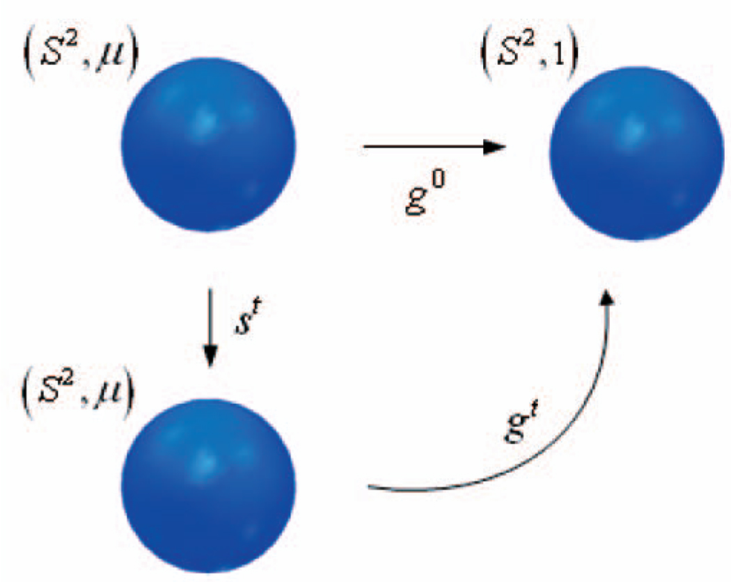
In our approach, we introduce a smooth, μ preserving, family of diffeomorphisms st : (S2, μ) → (S2, μ) and define the family of maps gt via
See Fig. 1. For t = 0, we define s0 to be the identity map. The idea given in [34], [4] is to use the family of maps st to rearrange the initial MP map g0 in such a manner to converge to the optimal solution. The family will be defined via a certain gradient flow defined for the minimization of the functional (6). We now give the details.
Fig. 1.
An illustration of the rearrangement of the map.
If the maps gt : S2 → S2 evolve so that
where st : S2 → S2 preserves the measure μ(x)dx, and where
then the gt satisfy the transport equation
| (7) |
We can accordingly write the evolution of the cost functional as follows:
| (8) |
The maps st will preserve the measure μ(x)dx if and only if the velocity field υt is divergence free, i.e., satisfies
| (9) |
Since S2 is two-dimensional, the general divergence-free vector field is of the form
| (10) |
where J is the rotation by +90 degree and H is some “Hamiltonian function.” See [18], [19] for all the details.
In general, using (10), one can compute that
Then, in order to obtain a gradient flow, one sets
| (11) |
so that the evolution of the cost function will be decreasing. In this setting, the maps should evolve by the following initial value problem:
| (12) |
2.4 Incorporating a Multiresolution Scheme to Our Flow
We now employ a wavelet representation to modify the gradient flow as proposed in the previous section. Accordingly, we can utilize a spherical wavelets basis ψj,m, such as the second generation biorthogonal wavelets introduced by Sweldens [67], [68], to represent H:
| (13) |
These wavelet functions can be defined intrinsically on the manifold and do not depend on its parameterization. Wavelet functions ψj,m represent functions on a regular grid at multiple levels of detail. Here, j indexes the scale (resolution of analysis), where higher j corresponds to higher resolution analysis, and m indexes the spatial location of analysis.
Any function q can be decomposed as a superposition of the biorthogonal basis ψj,m using a set of dual basis functions ψ̃j,m:
| (14) |
where γj,m denote the expansion coefficients. Therefore, using this biorthogonal wavelet basis to represent H as ∑j,m γj,m, ψj,m leads to the following evolution of the cost:
| (15) |
This, in turn, leads one to choose H as in (13) with
| (16) |
so that
Thus, in this case, the maps should evolve by the following initial value problem:
| (17) |
where γj,m(t) is as defined in (16).
In our gradient descent formulation, we can group the wavelet functions ψj,m according to their resolution level (j). Each of these groups can span any function defined over the manifold at a different resolution. We can then run our gradient flow at each resolution level separately, going from coarser to higher resolution, until it converges. This gradient flow will be obtained by iterating the following steps (starting with J = 1) until the MK cost functional ceases to decrease (or until ∫ H2 dx < ε for some tolerance ε > 0):
Using the basis vectors {ψj,m|1 ≤ j ≤ J, ∀m}, follow the steepest descent.
Increase J by 1, so as to include basis functions corresponding to the next level of resolution.
Moreover, the wavelet decomposition creates a natural setting for using multigrid methods, which we use to increase the efficiency of our method. In this case, we will first perform a few iterations (“relaxations”) using the expansion coefficients at all resolution levels. Then we will carry out several iterations, but every few iterations, we will pull out the coefficients of the highest resolution levels from the new representation, leaving a smoothed representation of our functions (this is equivalent to performing low-pass filtering). After reaching the lowest resolution level and performing a few iterations, we start operating in the opposite direction, by adding the coefficients of a higher resolution level every few iterations, until we reach the finest representation level. This will be referred to as the V-cycle. We perform a few such cycles until we obtain convergence to the solution.
2.5 Flow on S2
In the case of the sphere, with Φ(x, y) as the geodesic distance from x to y, we have
Φx is the projection of the derivative of Φ(x, y) as function from ℝ3 × ℝ3 → ℝ onto the tangent plane to S2 at x, therefore,
Since Jy = x × y and
we have
Therefore, in this setting, the maps should evolve by the initial value problem described in (17), where for γj,m (t) defined as in (16), we have
| (18) |
In the case of the sphere, we can use for the expansion the spherical wavelet basis that was introduced by Schröder and Sweldens [59], [60], which will explicitly be described in Section 3. Our flow stops when ∇ · (J Φx (x, gt)) is orthogonal to all the basis components. These points will now be described in the following section.
3 IMPLEMENTATION ISSUES
In this section, we will focus on how we maintain the correctness of the aforementioned mathematical derivation when we proceed to discrete settings.
3.1 Multiresolution Basis
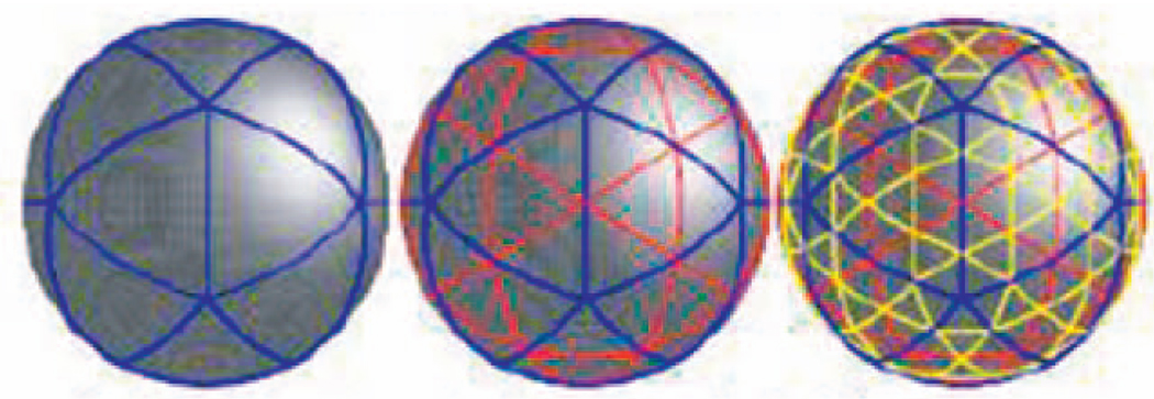
As alluded to above, in our implementation, we used the construction of the spherical wavelet basis introduced in [59], [60]. These are second generation wavelets, adapted to manifolds with nonregular grids. In the construction of these wavelets, a lifting scheme is used to obtain locally supported, biorthogonal spherical wavelets and their associated fast transforms. The construction of spherical wavelets relies on a recursive partitioning of the sphere into (spherical) triangles. This can be done starting from a Platonic solid of triangles (with 4 triangles forming a tetrahedron, 8 triangles forming an octahedron, or 20 triangles forming an icosahedron), and recursively subdividing the triangles into four child triangles at each stage of the recursion (quadtrees), as shown in Fig. 2.
Fig. 2.
Two subdivision steps starting from a spherical icosahedron.
On this mesh, we denote the set of all vertices obtained after j ∈ J subdivisions by K (j). The (j + 1)th resolution mesh is obtained by introducing new nodes, identified by M (j), which subdivide existing edges (typically at their midpoint). The complete set of nodes in the (j + 1)th resolution mesh is given by K(j + 1) = K(j) ∪ M(j).
At resolution level j, a scaling function φj,k is defined for every vertex k ∈ K (j). One commonly used scaling function is the hat scaling function that varies linearly from the value 1 at vertex k to 0 at its immediate neighboring vertices. The scaling functions satisfy the refinement relation, therefore, each scaling function φj,k can be written as a linear combination of scaling functions of the next finer level:
with {hj,k,l|j ∈ J, k ∈ K(j), l ∈ K(j + 1)} defining a finite filter.
If q : S2 → ℝ is a function defined on S2, we can approximate the function q at a resolution j by an expansion of the form
The coefficients λj,k are called scaling coefficients and formally given by the inner products λj,k = 〈φ̃j,k; q〉, where φ̃ is the dual scaling function which satisfies
The scaling coefficients represent the low-pass information of the original signal. Scaling coefficients of lower resolution levels represent smoother versions of the data.
If we wish to perform a multiresolution expansion, we can do so by writing the approximation using wavelet functions that are located at the mesh subdivision points ψj,m, instead of the scaling functions. For the hat scaling function, the corresponding wavelet functions may be written as
The weights sj,m,k are chosen so that the resulting wavelet has a vanishing integral (for details, see [67], [68]). For q ∈ L2, we can write the expansion
The coefficients γj,m are called wavelet coefficients and formally given by the inner products γj,m = 〈q, ψ̃j,m〉, where ψ̃j,m is a dual wavelet function.
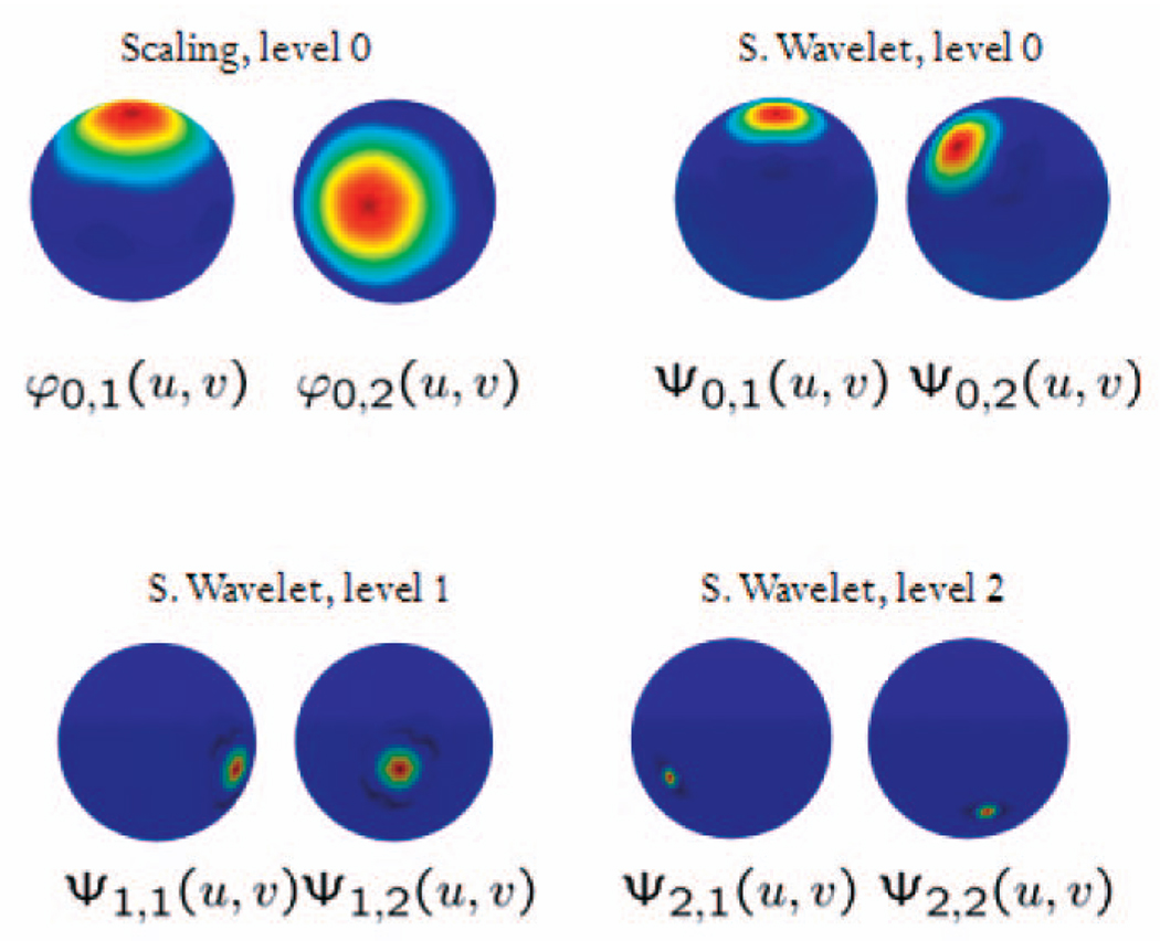
The intermediate wavelet coefficients represent band pass information and the highest resolution wavelet coefficient represents the high-pass information. The coarsest level scaling function and all wavelet scaling functions construct a basis for the function space L2. See Fig. 3 for examples of spherical wavelets and a scaling function.
Fig. 3.
Some examples of spherical wavelets and a scaling function.
3.2 Discretization
Our approach for discretizing the gradient flow (17) has its mathematical foundation in Discrete Exterior Calculus (DEC) theory that was proposed in [38], [15]. The power of this method is the careful definition of discrete differential quantities, designed to respect structural relationships such as vector calculus identities. This is quite different from previous methods, which focused on satisfying the continuous equations at a discrete set of spatial and temporal samples, but failed to preserve important global structures and invariants. Both fluid mechanics and electromagnetism make heavy use of line integrals, as well as surface and volume integrals. Pointwise evaluations or approximations for such quantities may not be the appropriate discrete analogs, since the defining geometric properties underlying their physical meaning cannot be enforced naturally. Instead, one should store and manipulate those quantities at their geometrically meaningful locations; one should consider values on vertices, edges, and faces as proper discrete versions of pointwise functions, line integrals, and surface integrals, respectively.
The main idea behind this approach is the representation of fields through measurements on cells: a 0-form represents a scalar function through its values at vertices (0-dim cells), while a 1-form represents a tangent vector field through its line integral along edges (1-dim cells). This implies that tangent vector fields are specified as a single scalar per edge on the mesh. A 2-form represents area density through its area integral over triangles (2-dim cells). All relevant computations are then performed on these coefficients and the results are reconstructed with piecewise linear (PL) interpolation.
This theory defines discrete differential k-forms on triangular meshes and expresses relevant operators such as divergence, curl, gradient, and Laplacian, as simple sparse matrices acting on intrinsic (coordinate-free) coefficients “living” on vertices, edges, and triangles. This concept greatly simplifies the implementation as all variables are intrinsic. It also ensures that the approach works for general manifolds without any changes.
Our main concern when we cross over to the discrete setting is to maintain the MP property of our velocity vector field. In the continuous case, we set the velocity field to be
so that μ0υt is divergence free, and thus, satisfies the MP requirement. In the discrete setting, we have to choose the gradient and the divergence operators so that they satisfy this property, i.e., we must show that using the DEC definitions, one has
where H is a scalar function that takes its values on the vertices. This is done in Appendices A and B.
4 ALGORITHM FOR TEXTURE MAPPING
Once we find the optimal mapping from a general simply connected compact surface Ω to the sphere S2, we can use the inverse mapping to “paint” the surface with any texture defined on the sphere. We assume that the total surface area of Ω has been normalized to be 4π. Summarizing, the steps we need to perform to find the optimal mapping are as follows (see Fig. 4):
We construct a conformal mapping f from Ω to the sphere S2. (This is unique up to Moebius transformation.) We define a density function on S2 that corresponds to area distortion of this mapping. This density function is μ = |∇f−1|.
We find an initial MP mapping g0 : (S2, μ) → (S2, 1). The composition of this mapping and the conformal mapping produced an area preserving mapping from a general surface to the sphere.
We minimize the cost functional M (g) of the map g0 by evolving the map g0 over time according to the gradient flow (17).
Fig. 4.
A block diagram of the algorithm for the optimal mapping calculation.
The composition gt→∞ ○ f will give us the required area preserving mapping from Ω to the sphere. We can then synthesize an image on the sphere, attributing a color to every vertex or triangle, and use the inverse mapping (g∞ ○ f)−1 to map this image onto the original surface.
In the following sections, we will elaborate on the implementation of each of these steps.
4.1 Finding the Conformal Mapping
We employ the method for conformal mapping proposed in [5]. We briefly outline the relevant steps. The idea is to remove a triangle, solve the Dirichlet problem, and thus, conformally map the remaining surface onto the complex plane, and finally, use the inverse stereo projection to map the plane onto S2. The boundary is mapped to a triangle around the “North Pole” of S2.
More precisely, we start with a manifold represented by a triangular mesh with N vertices from which we remove one triangle ΔABC and then perform the following steps:
-
Calculate the matrix D.
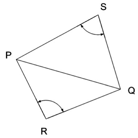
D is a sparse and symmetric N × N matrix whose nonzero elements DPQ (P ≠ Q) are
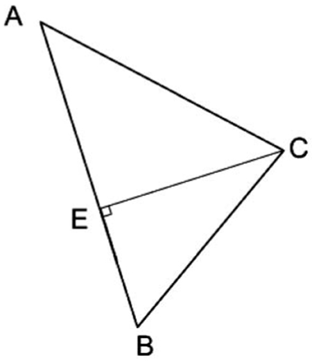
where ∠R is the angle at the vertex R in the triangle ΔPQR and ∠S is the angle at the vertex S in the triangle ΔPQS (see Fig. 4a).Note that DPQ ≠ 0 only if P and Q are connected by some edge in the triangulation. The diagonal elements DPP satisfy -
Calculate the vectors a and b.
The variables a and b are sparse N vectors with an entry for each vertex. Their nonzero elements are found at the vertices A, B,C of the triangle ΔABC that we removed from the mesh:
where E is the orthogonal projection of C on AB (see Fig. 4a) and - Solve the linear system of equations:
- Map the x and y coordinates from the plane to the unit sphere using inverse stereographic projection:
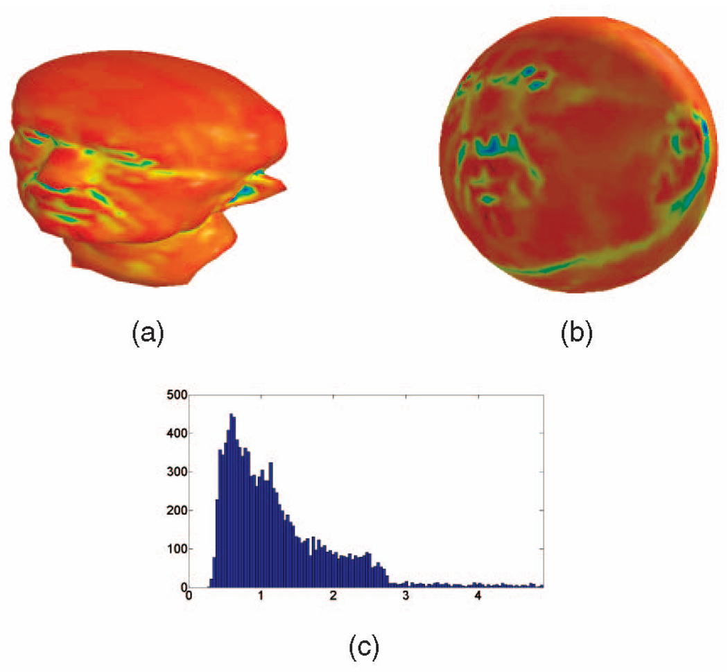
As noted above, the conformal mapping distorts the area of the surface (see Fig. 5, where the nose of the “Max Planck” image is mapped to a smaller area with proportion to his eyes). We quantify the change of area as the density function μ at each point on S2 so that the integral on the flattened surface ∫S2 μdx will give us the area measure of the original surface. In continuous settings this density function is the determinant of the Jacobian of f−1:
Fig. 5.
(a) The initial three-dimensional “Max Planck” surface. The color indicates the mean curvature (red indicates positive mean curvature—convex areas, while blue indicates negative mean curvature—concave areas, and green indicates mean curvature values close to zero—saddle points). (b) “Max Planck” after conformal mapping to the sphere. The colors of every point are the same color as the corresponding point in (a). (c) Area ratio histograms for the “Max Planck” surface before versus after conformal flattening.
In the discrete settings, we calculate the area distortion for each triangle as the ratio of the area of the triangle on the original surface Ω to the area of its corresponding triangle on the flattened surface S2 after the conformal mapping.
4.2 Finding the Initial MP Mapping
For a general domain, the initial MP mapping can be obtained using the method proposed by Moser [52]. We won’t repeat here the derivation of Moser’s method for finding an area preserving mapping, but rather just give the final algorithm that is applicable to all of our examples. Details may be found in [52], [13]. As mentioned above, the area preserving mapping from the original surface to the sphere will be the composition of the mapping g and the conformal mapping f. The mapping g is calculated by solving two differential equations on the sphere. We first solve
for Θ, with
and then set
for t ∈ [0, 1]. Finally given the family ut, we solve for gt from the ODE
with g0 taken to be the identity mapping. Then, g = g1 is our required mapping.
After performing Step 2, we have an area preserving mapping with respect to the original domain g ○ f. However, this area preserving mapping is still not optimal in the transport sense defined above. In the next step, we will evolve this mapping to the optimal one.
4.3 Finding the Optimal MP Mapping
We now use the MP mapping obtained in Step 2, from now on, denoted by g0, as the initial mapping for the optimal transport algorithm. We will evolve g0 over time to obtain gt using the gradient descent flow as defined by the initial value problem (17). As t goes to infinity, gt will converge to the optimal mapping.
We start by calculating μ as the area distortion of every face after the conformal mapping. μ is calculated as the ratio of the original area of each triangle face to its area on the sphere after conformal mapping. It should be emphasized that this calculation is performed after we scale the original surface so that its surface area is 4π (same as the area of the unit sphere). We then find the vertices of the dual mesh (denoted by xd) as the circumcenters of the triangles. Henceforth, all quantities referring to the dual mesh will be denoted by a subscript d and those referring to the primal mesh will be denoted by a subscript p. The vectors of the initial mapping g0 are interpolated at the vertices of the dual mash and denoted by gd. The mapping g0 at the original vertices will be denoted by gp. The following steps are performed iteratively until we converge to the optimal mapping.
We calculate at the dual mesh vertices and then calculate the value of the function Hp at the vertices of the original mesh as the divergence of . Then, we find the coefficients of its representation after the spherical wavelet transform. We will next use only some of these coefficients—at each iteration, we choose the coefficients according to our stage in the multigrid algorithm (this concept will be clarified in the next paragraph). We perform the inverse transform using these coefficients only. We then calculate our velocity field (at the vertices of the dual mesh) as . Note that the result of the computation of the gradient is given at the vertices of the dual mesh.
We next update gd according to this velocity field as gd − dt ∇ gp · υd. This update is found by first interpolating gd at the vertices of the primal mesh xp and then calculating the Jacobian of gp using our formulation for the gradient calculation. Here, dt is the time step. The process is now repeated with the updated gd. We use smaller time steps when we update our mapping using higher resolution coefficients. The algorithm is sketched in pseudocode (1).
Algorithm 1.
Perform One Step Toward Optimal MP Mapping
|
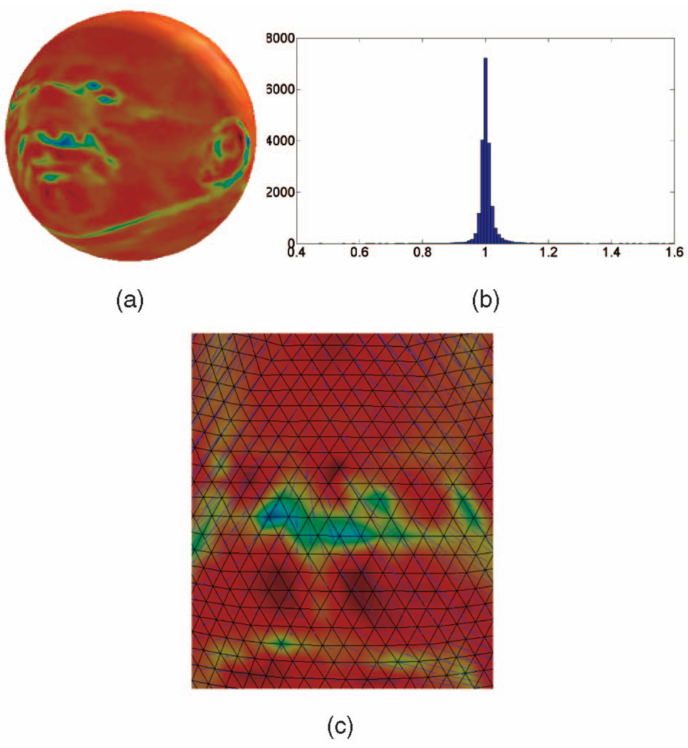
The repetitions of the above steps are performed while using a different set of wavelet coefficients each time. As mentioned in Section 2, we cluster the wavelet functions ψj,m according to their resolution level (j). Then, as explained in Section 2.4, we perform several V-cycles until we obtain convergence to the solution (see Fig. 6). These steps are summarized in pseudocode (2).
Fig. 6.
(a) “Max Planck” after area preserving mapping obtained using our gradient descent method. This mapping causes minimal local geometry distortion in the sense described in the text. (b) The area ratio histogram for the “Max Planck” surface before the mapping versus after the optimal area preserving mapping. (c) The blue arrows show the vector field that moves the vertices to create the optimal mapping on the nose area.
Algorithm 2.
Calculate Optimal MP Mapping
|
5 EXAMPLES
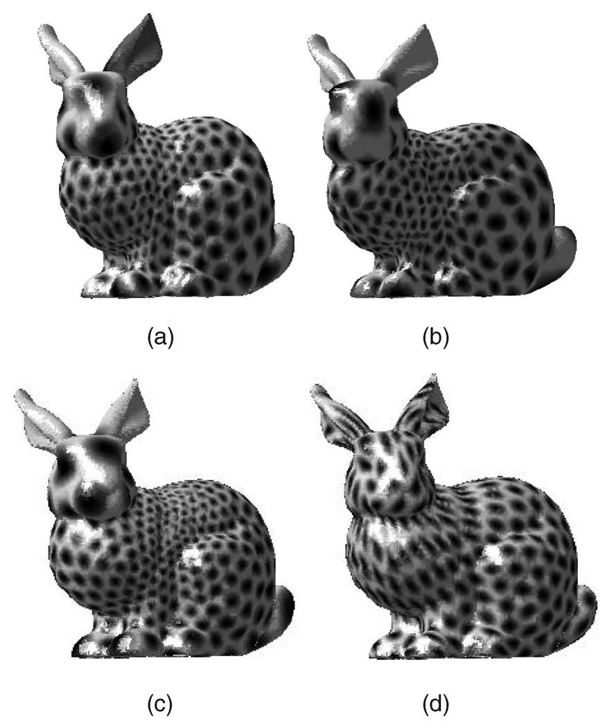
In this section, we give some examples illustrating our use of optimal mass transport for texture mapping. We should note that in some previous work [35], conformal mapping theory was applied to the problem of texture mapping, and so in the examples below, we explicitly compare the optimal mass transport approach to this one. In Fig. 13, we also compare texture mapping using our parameterization to texture mapping and using the parameterization proposed in [57] and [30].
Fig. 13.
Circles mapped onto the Stanford Bunny using the parameterization method of Gotsman et al. [30] with (a) mean value weights and (b) Tutte weights. (c) Mapping using the conformal parameterization of Haker et al. [35] and (d) texture mapping using our optimal MP parameterization.
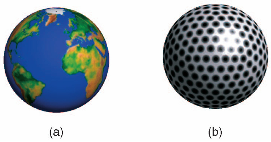
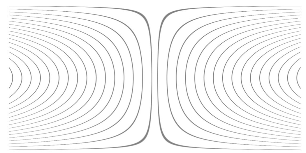
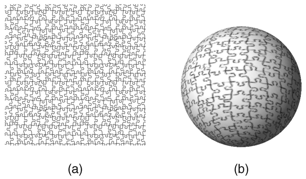
Some of the textures we used were created directly on the sphere, such as the case of the circles pattern, or images taken with an omnidirectional camera, as can be seen in Fig. 7. However, most of the images were created on a 2D rectangle and then mapped to the sphere using the (inverse) equirectangular projection. The equirectangular projection maps the longitudes and latitudes directly into the x and y coordinates on the plane, respectively. The poles (zenith, nadir) are mapped to the top and bottom edges and are stretched to the entire width of the image. Areas near the poles get stretched horizontally. This projection is easy to use because of the simple connection between the pixel coordinates on the plane and its azimuth and zenith angles on the sphere. However, it is neither area preserving nor conformal. Therefore, a preliminary step of correcting a given texture image has to take place in order to account for this distortion. This correction can be performed by transforming the azimuth angles. Assume that the image values are mapped vertically onto lines of latitude and mapped horizontally onto lines of longitude (− π < ϕ ≤ π). In order to correct the distortion, there is no need to modify θ, but ϕ is scaled as we approach the two poles by cos(θ). In Fig. 8, one can see the lines on the 2D image that correspond to the lines of longitude after the transformation. An example of this mapping can be seen in Fig. 9.
Fig. 7.
Texture synthesized over the sphere.
Fig. 8.
2D image lines corresponding to the lines of longitude (see text).
Fig. 9.
(a) Texture image mapped onto the sphere (b) after warping.
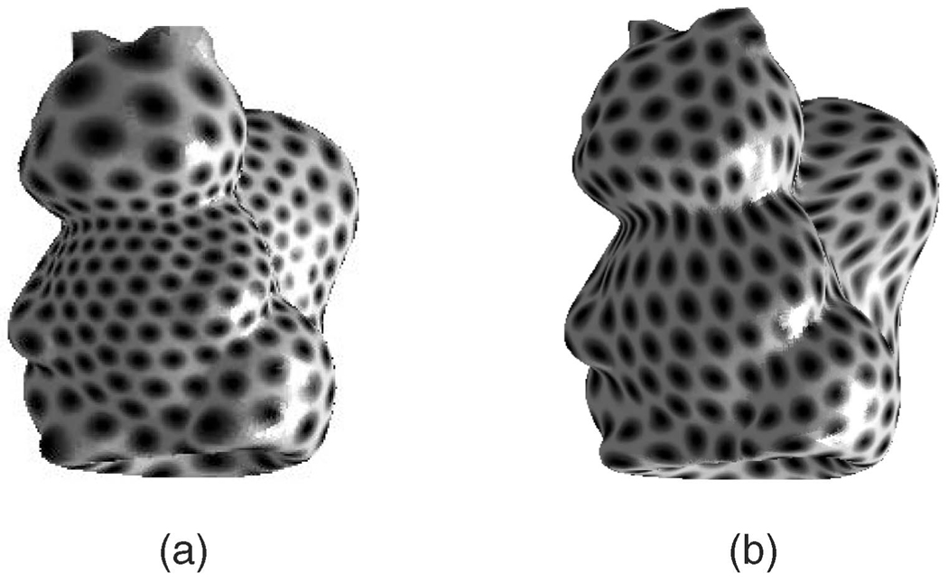
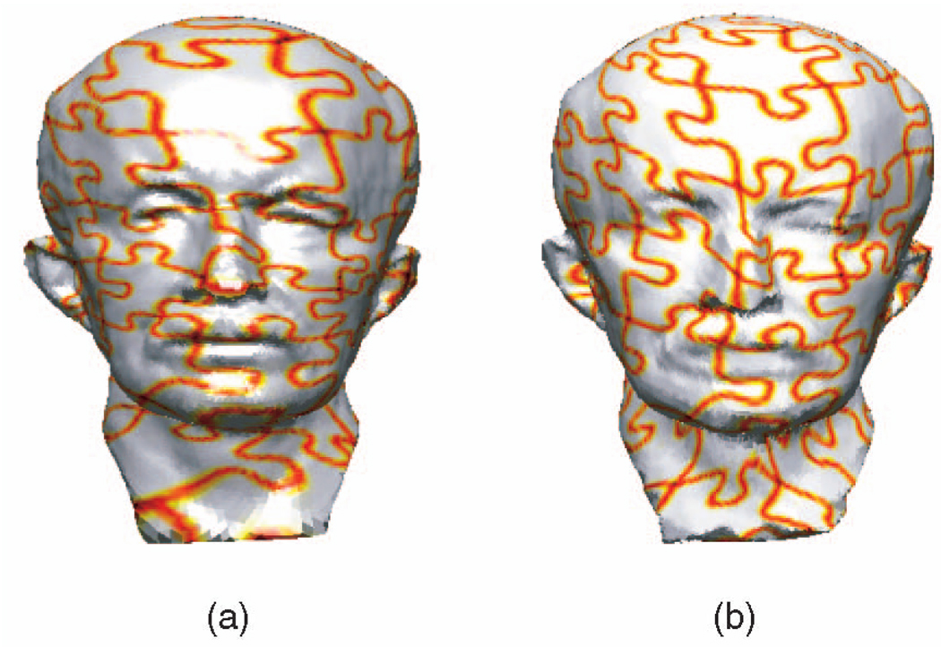
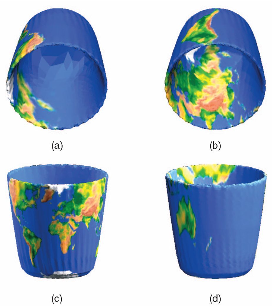
Once we have the synthesized texture over the sphere, we use the inverse of our mapping (derived via optimal mass transport) to map this texture from the sphere to the 3D object as described above. In the mapping results in Figs. 10 and 11, one can see how our mapping corrects the area distortion with respect to the conformal but still manages to minimize the geometrical distortion. Note that in Fig. 10, the conformal mapping maintains the shape of the circles but may scale them differently, so that in some places, the circles are very large, while in others, they are quite small. In our mapping, all the circles are practically the same size, whereas the geometrical distortions are local and small. In Fig. 11, one can see the same effect for the puzzle texture. In Fig. 12, this improvement in quality is even more striking, since in this case because of the high curvature changes, the conformal mapping causes major area distortions, and almost all the land of the earth is mapped to a small portion of the bucket. Our mapping places the north pole on the bottom inside the bucket and the south pole on the bottom of the bucket from outside, so the rest of the world is evenly spread on the whole surface. In Fig. 13, texture mapping using our method is compared to the texture mapping results obtained using the parameterization method proposed in [57] and [30] for the Stanford bunny. In this case, while the extremities of the bunny’s ears impose on most other parameterization methods a very dense parameterization, in our method, this is avoided. However, in this case, the geometrical distortion is fairly noticeable, despite being local.
Fig. 10.
Circles mapped onto the squirrel using (a) conformal mapping and (b) our optimal MP mapping.
Fig. 11.
Puzzle mapped onto “Max Planck” using (a) conformal mapping and (b) our optimal MP mapping.
Fig. 12.
The globe mapped onto the bucket using ((a) and (c)) conformal mapping and ((b) and (d)) our optimal MP mapping.
6 EVALUATION
We experimented with our code using a Matlab and mexed C++ implementation on a standard 2 GHz CPU with 2 GB RAM processor. Most of the code was implemented in Matlab, except for some spherical wavelet transform functions.
In order to quantify the distortion of the parameterization, we compute both the angle and area distortion metrics defined using the signed singular values of the Jacobian of the transformation for each triangle, as presented in [40], [14], and [49]. Small angular and area distortions are indicated by a distortion value approaching 2. We ran our algorithm, referred to as MK, on a variety of inputs, in order to evaluate the computation time and convergence rate. We compared the results of the MK algorithm with the results obtained after running the algorithm of Haker et al. [34] and that of Moser’s [52]. We also compared our results to those obtained using the method of Gotsman et al. [30] with Tutte weights and Mean-Value weights (using the implementation of Saba et al. [57]). The values of the distortion measures obtained by the various algorithms are summarized in Tables 1 and 2. One can see that the proposed algorithm produces maps with very small area distortion that also minimizes the angular distortion.
TABLE 1.
Angular Distortion Statistics
| Model | # of faces |
Saba Tutte |
Saba Mean |
Haker | Moser | MK |
|---|---|---|---|---|---|---|
| Gargoyle | 20k | 2.53 | 2.458 | 2.153 | 2.97 | 2.33 |
| Max-Planck | 25k | 2.62 | 2.15 | 2.004 | 2.38 | 2.29 |
| Skull | 40k | 2.55 | 2.12 | 2.11 | 2.23 | 2.2 |
| Bunny | 70k | 2.65 | 2.52 | 2.02 | 3.17 | 2.76 |
TABLE 2.
Area Distortion Statistics
| Model | # of faces |
Saba Tutte |
Saba Mean |
Haker | Moser | MK |
|---|---|---|---|---|---|---|
| Gargoyle | 20k | 4.03 | 4.16 | 3.78 | 2.51 | 2.61 |
| Max-Planck | 25k | 2.67 | 2.32 | 2.37 | 2.004 | 2.007 |
| Skull | 40k | 2.71 | 2.4 | 2.39 | 2.01 | 2.01 |
| Bunny | 70k | 3.47 | 3.65 | 3.26 | 2.57 | 2.66 |
Running time of our algorithm for meshes of varying sizes is summarized in Table 3. The experiments we performed show that the number of iterations required for convergence is not determined solely according to the mesh size, and is in fact, even more affected by the extremities of the excrescences of the meshes. It should be noted that in our research within the medical imaging field, the meshes we use are those of anatomical structures, which do not have such extremities, and thus, we did not have to deal with this issue. However, we note that in case of such large extremities, besides longer computation time, triangle flipping may also occur in the Moser algorithm, as discussed below.
TABLE 3.
Performance Statistics
| Model | # of faces | # of iterations | time(sec) |
|---|---|---|---|
| Squirrel | 5k | 814 | 971 |
| Gargoyle | 20k | 1687 | 1451 |
| Max-Planck | 25k | 2120 | 2460 |
| Skull | 40k | 1371 | 2132 |
| Bunny | 70k | 2530 | 3093 |
The calculation that dominates the computation time is that of finding the coefficients of the spherical wavelets representation. Otherwise, the computations in each iteration of the algorithm can be performed in parallel, therefore, an implementation on a GPU would probably eliminate most of the increase in running time versus mesh size that is evident in Table 3.
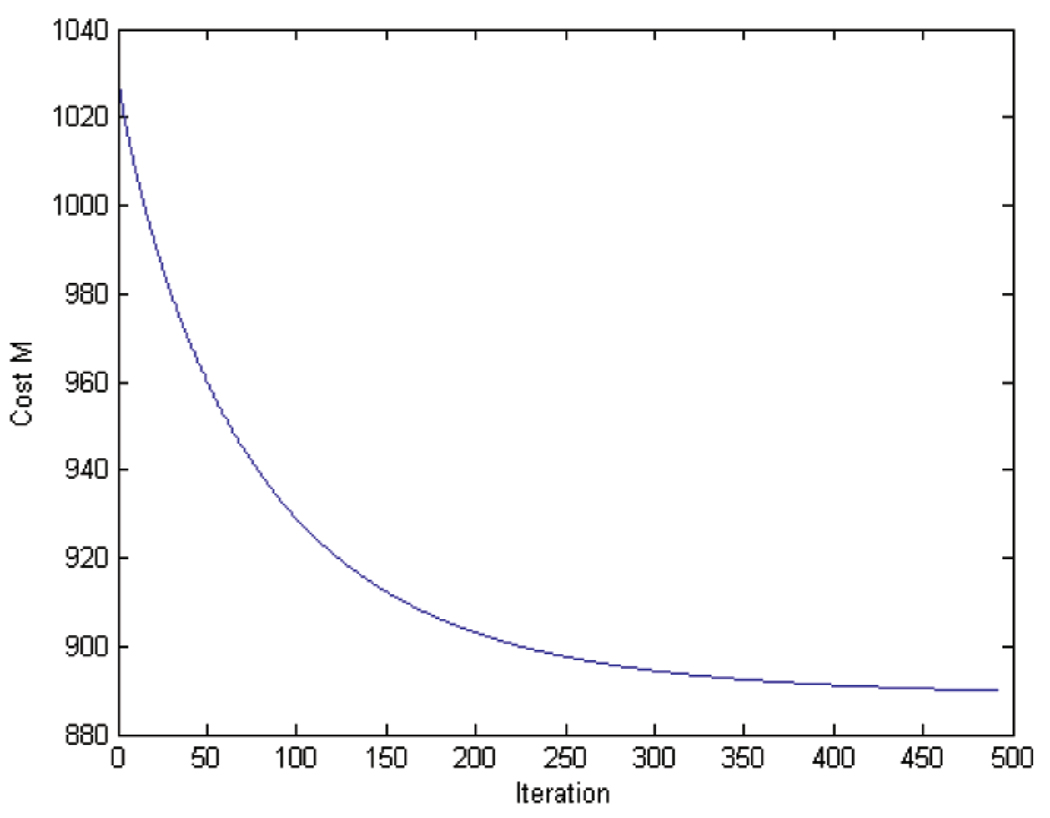
The convergence behavior of our algorithm for the Squirrel example is shown in Fig. 14. Obviously, one can see that the convergence rate is not linear and it takes a few hundred iterations to converge to the optimal solution. However, after several hundred iterations, the algorithm reaches a solution that is fairly close to the optimal solution.
Fig. 14.
The evolution of the cost M as defined in (6) versus the iteration number.
It should be noted that our method is immune to triangle flipping. In the continuous setting, this is imposed by the bijectivity of our mapping (that can easily be shown using the maximum principle). In the discrete setting, we enforce bijectivity by using an implementation of the differential equations according to the DEC theory. As shown in Appendix B, this implementation allows us to maintain the mass preserving property of our velocity field even in the discrete settings, and thus, prevent triangle flipping. However, since the methods described in [34] and [52] are not bijective in the discrete settings, triangle flipping may occur in the preparation stages for our algorithm. Our algorithm cannot recover from triangle flipping in these stages. Therefore, for meshes with large extremities in which triangle flipping may occur (rarely in the method of [34] and more often in the method of [52]), an additional step of fixing these flips has to be applied to the mesh. Of course, this step may come at the cost of locally increasing the distortions.
7 CONCLUSION AND FUTURE WORK
In this paper, we introduced a novel method for the parameterization of 3D objects. In the proposed method, we find the optimal mapping in the sense that it is the area preserving mapping produced via optimal mass transport. The optimal mass transport map is found via a gradient flow directly computed on the sphere, implemented using a multiresolution scheme for fast convergence. We have also shown how we can use our method to map textures onto closed compact simply connected surfaces and compared our results to texture mappings derived from conformal mapping theory.
There are several directions that we plan to pursue in future work. First of all, we believe that we can improve the rate of convergence of our algorithm by refining the multigrid scheme. Further, we want to extend our methodology to higher genus surfaces. This is not completely straightforward since in this case, the general divergence-free vector field (on a two-dimensional surface) involves a harmonic term. In the simply connected case, this does not appear. In general, for a surface of genus g, the space of such harmonic forms has dimension 2g. However, we believe that this is tractable and this extension will make our method applicable for texture mapping on more complicated surfaces. It should also be noted that an algorithm for computing harmonic 1-form group basis of a high genus surface has been introduced by Gu and Yau based on Hodge theory in [32].
Finally, we plan to apply our algorithm to real medical data including brain structures such as the caudate nucleus and hippocampus (whose surfaces are topological spheres) to support the work in statistical shape analysis for our research in schizophrenia.
ACKNOWLEDGMENTS
This work was supported in part by grants from the US National Science foundation (NSF), AFOSR, ARO, MURI, as well as by a grant from NIH (NAC P41 RR-13218) through Brigham and Women’s Hospital. This work is part of the National Alliance for Medical Image Computing (NAMIC), funded by the National Institutes of Health through the NIH Roadmap for Medical Research, Grant U54 EB005149. Information on the National Centers for Biomedical Computing can be obtained from http://nihroadmap.nih.gov/bioinformatics.
Biographies
Ayelet Dominitz is currently working toward the PhD degree at the Technion. She works in computer vision and image processing. She is a student member of the IEEE.

Allen Tannenbaum is a faculty member at the Technion and Georgia Institute of Technology. He works in computer vision, image processing, and control. He is a fellow of the IEEE.
APPENDIX A
DEC OPERATORS
In our implementation, we use the formulation of the DEC theory in [38]. Here, we repeat some of the key points in the derivation of the gradient and divergence operators.
A.1 Gradient
For a function f (a primal 0-form), the gradient can be computed in the interior of the triangles (the primal simplices) by first interpolating the function from the primal vertices to the interior using affine, barycentric interpolation functions, and then taking the gradient. Since the interpolation is affine, the gradient is a constant vector, and we can associate it with the dual of the simplex.
The set of interpolating functions we use is defined as follows. The interpolation function φi has the value 0 at all vertices other than vertex i and the value 1 at vertex i. The piecewise linear interpolation of the discrete function f at a point x in any triangle ΔABC can be written as
Taking the usual gradient of this smooth function in ΔABC, we have
| (19) |
In general, we have
By substituting this into (19), we get
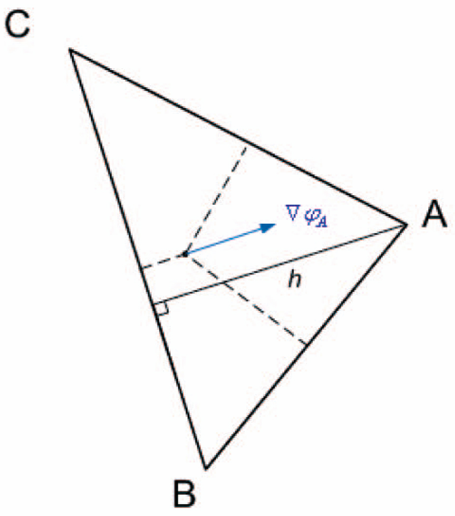
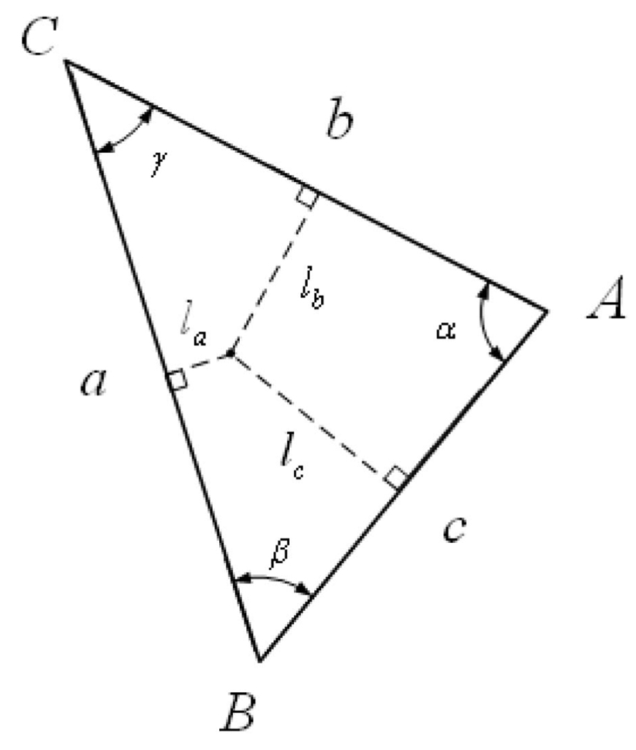
The gradient value is independent of which vertex is chosen as the distinguished vertex C. The gradient of the interpolating function in triangle ΔABC is perpendicular to the edge opposite the vertex from which the interpolating function stems, and its magnitude is , where h is the length of the perpendicular line from the vertex to the edge, as shown in Fig. 15.
Fig. 15.
The gradient of the interpolating function φA.
A.2 Divergence
Let us denote the directed edges stemming from a vertex i by eij for j = 1, 2, …, n, where n is the number of mesh triangles that contain the vertex i. We denote by an edge perpendicular to eij that connects the circumcenters (the dual vertices) of the triangles adjacent to the edge eij. (Note that this is not a directed edge.) Each of these edges has two triangles adjacent to it. We denote the two triangles adjacent to an edge eij by Δijk for k = 1, 2. The divergence of a vector field V at vertex xi can then be calculated as
where Ai is the area of the Voronoi cell around vertex i (this is the area of the region bounded by the edges at vertex i) and êij is the unit vector pointing in the direction of the directed edge eij. Note that this formula corresponds to the net flow per unit volume of an infinitesimal volume about a point, which is the physical intuition of divergence. A more detailed explanation of this formula may be found in [38].
APPENDIX B
PROOF OF MP PROPERTY
Here, we show that, if we use the operators defined in Appendix A for the gradient and divergence, we maintain the MP property of our velocity field, which is defined as
If we take our gradient and divergence operators as proposed in the DEC theory (see Appendix A for the formulations of these operators and their justification), we can show that
if H is a scalar function that takes its values on the vertices. The notation used in the following proof is elaborated in Fig. 16. Without loss of generality, we need only consider the contribution to the divergence at vertex xA from triangle ΔABC.
Fig. 16.
Notation for the MP proof.
Our velocity field υ is calculated as follows. First, we calculate the gradient of the scalar function H:
| (20) |
We calculate the gradients of the interpolating functions as
Substitution of these two expressions into (20) gives us
| (21) |
Therefore, the velocity field, obtained by 90 degree rotation of the above, is
| (22) |
We now take the divergence of our velocity field:
| (23) |
Using the properties of the circumcenter, we get
and
Substitution of these two equations into (23) results in
| (24) |
Now, using the sine formula , we get
| (25) |
Recall that is the contribution to the divergence at vertex xA from one of its adjacent triangles. If we sum over the contributions from all surrounding triangles, we will get that the value of the scalar function H at each of the surrounding vertices will show up once with a positive sign and once with a negative sign—and will, therefore, cancel out, adding to a total divergence of zero.
Contributor Information
Ayelet Dominitz, Department of Electrical Engineering, Technion—IIT, Haifa 32000, Israel. ayeletdo@tx.technion.ac.il.
Allen Tannenbaum, Schools of ECE and BME, Georgia Institute of Technology, Atlanta, GA 30332, and the Department of Electrical Engineering, Technion—IIT, Haifa 32000, Israel. allen@ee.technion.ac.il.
REFERENCES
- 1.Alexa M. Recent Advances in Mesh Morphing. Computer Graphics Forum. 2002;vol. 21(no. 2):173–196. [Google Scholar]
- 2.Ambrosio L. Lecture Notes on Optimal Transport Problems. Proc. Euro Summer School Lectures. 2000 July [Google Scholar]
- 3.Angenent S, Haker S, Tannenbaum A, Kikinis R. On Area Preserving Maps of Minimal Distortion. In: Djaferis T, Schick I, editors. System Theory: Modeling, Analysis, and Control. Kluwer; 1999. pp. 275–287. [Google Scholar]
- 4.Angenent S, Haker S, Tannenbaum A. Minimizing Flows for the Monge-Kantorovich Problem. SIAM J. Math. Analysis. 2003;vol. 35:61–97. [Google Scholar]
- 5.Angenent S, Haker S, Tannenbaum A, Kikinis R. Laplace-Beltrami Operator and Brain Surface Flattening. IEEE Trans. Medical Imaging. 1999 Aug.vol. 18(no. 8):700–711. doi: 10.1109/42.796283. [DOI] [PubMed] [Google Scholar]
- 6.Benamou J-D, Brenier Y. A Computational Fluid Mechanics Solution to the Monge-Kantorovich Mass Transfer Problem. Numerische Math. 2000;vol. 84:375–393. [Google Scholar]
- 7.Ben-Chen M, Gotsman C, Bunin G. Conformal Flattening by Curvature Prescription and Metric Scaling. Computer Graphics Forum. 2008;vol. 27(no. 2) [Google Scholar]
- 8.Blinn JF, Newell ME. Texture and Reflection in Computer Generated Images. Comm. ACM. 1976;vol. 19:542–546. [Google Scholar]
- 9.Blinn JF. Simulation of Wrinkled Surfaces. Proc. ACM SIGGRAPH. 1978;vol. 12(no. 3):286–292. [Google Scholar]
- 10.Brenier Y. Polar Factorization and Monotone Rearrangement of Vector-Valued Functions. Comm. Pure and Applied Math. 1991;vol. 64:375–417. [Google Scholar]
- 11.Catmull E. PhD thesis. Dept. of Computer Science, Univ. of Utah; 1974. Dec., A Subdivision Algorithm for Computer Display of Curved Surfaces. [Google Scholar]
- 12.Cullen M, Purser R. An Extended Lagrangian Theory of Semigeostrophic Frontogenesis. J. Atmospheric Sciences. 1984;vol. 41:1477–1497. [Google Scholar]
- 13.Dacorogna B, Moser J. On a Partial Differential Equation Involving the Jacobian Determinant. Annales de l’institut Henri Poincaré (C) Analyse Non Linéaire. 1990;vol. 7:1–26. [Google Scholar]
- 14.Degener P, Meseth J, Klein R. An Adaptable Surface Parameterization Method; Proc. 12th Int’l Meshing Roundtable; 2003. pp. 201–213. [Google Scholar]
- 15.Desbrun M, Kanso E, Tong Y. Discrete Differential Forms for Computational Modeling. Proc. ACM SIGGRAPH. 2006 [Google Scholar]
- 16.Desbrun M, Meyer M, Alliez P. Intrinsic Parameterizations of Surface Meshes. Computer Graphics Forum. 2002;vol. 21(no. 3):209–218. [Google Scholar]
- 17.Do Carmo MP. Differential Geometry of Curves and Surfaces. Prentice-Hall, Inc.; 1976. [Google Scholar]
- 18.Dominitz A, Angenent S, Tannenbaum A. A Multi-Resolution Approach for Optimal Mass Transport; Proc. Conf. Soc. Photo-Optical Instrumentation Engineers (SPIE); 2007. [Google Scholar]
- 19.Dominitz A, Angenent S, Tannenbaum A. On the Computation of Optimal Transport Maps Using Gradient Flows and Multiresolution Analysis. In: Blondel V, Boyd S, Kimura H, editors. Recent Advances on Control and Learning. Springer-Verlag; 2008. [Google Scholar]
- 20.Evans LC. Partial Differential Equations and Monge-Kantorovich Mass Transfer. In: Yau ST, editor. Current Developments in Math. Int’l Press; 1999. pp. 65–128. [Google Scholar]
- 21.Feldman M, McCann RJ. Monge Transport Problem on a Riemannian Manifold. Trans. Am. Math. Soc. 2002;vol. 354:1667–1697. [Google Scholar]
- 22.Floater MS. Mean Value Coordinates. Computer Aided Geometric Design. 2003;vol. 20(no. 1):19–27. [Google Scholar]
- 23.Foley J, van Dam A, Feiner S, Hughes J. Computer Graphics. Addison-Wesley Publishing; 1992. [Google Scholar]
- 24.Fry D. PhD thesis. Harvard Univ.; 1993. Shape Recognition Using Metrics on the Space of Shapes. [Google Scholar]
- 25.Gangbo W. An Elementary Proof of the Polar Factorization of Vector-Valued Functions. Archive for Rational Mechanics and Analysis. 1994;vol. 128:381–399. [Google Scholar]
- 26.Gangbo W, McCann R. The Geometry of Optimal Transportation. Acta Math. 1996;vol. 177:113–161. [Google Scholar]
- 27.Gangbo W, McCann R. Shape Recognition via Wasserstein Distance, technical report, School of Math. Georgia Inst. of Technology; 1999
- 28.Gomes J, Darsa L, Costa B, Velho L. Warping and Morphing of Graphical Objects. Morgan Kaufman Publishers; 1998. [Google Scholar]
- 29.Gu X, Gortler S, Hoppe H. Geometry Images. Proc. ACM SIGGRAPH. 2002:356–361. [Google Scholar]
- 30.Gotsman C, Gu X, Sheffer A. Fundamentals of Spherical Parameterization for 3D Meshes. ACM Trans. Graphics. 2003;vol. 22(no. 3):358–363. [Google Scholar]
- 31.Gu X, Yau S-T. Computing Conformal Structures of Surfaces. Comm. Information and Systems. 2002;vol. 2(no. 2):121–146. [Google Scholar]
- 32.Gu X, Yau S-T. Global Conformal Parameterization. Proc. First Eurographics Symp. Geometry Processing. 2003 June;:127–137. [Google Scholar]
- 33.Gu X, Wang Y, Chan TF, Thompson PM, Yau S-T. Genus Zero Surface Conformal Mapping and Its Application to Brain Surface Mapping. IEEE Trans. Medical Imaging. 2004 Aug.vol. 23(no. 8):949–958. doi: 10.1109/TMI.2004.831226. [DOI] [PubMed] [Google Scholar]
- 34.Haker S, Zhu L, Tannenbaum A, Angenent S. Optimal Mass Transport for Registration and Warping. Int’l J. Computer Vision. 2004;vol. 60:225–240. [Google Scholar]
- 35.Haker S, Angenent S, Tannenbaum A, Sapiro S, Halle M. Conformal Surface Parametrization for Texture Mapping. IEEE Trans. Visualization and Computer Graphics. 2000 Apr.–June;vol. 6(no. 2):181–189. [Google Scholar]
- 36.Heckbert PS. Survey of Texture Mapping. IEEE Computer Graphics and Applications. 1986 Nov.vol. 6(no. 11):56–67. [Google Scholar]
- 37.Heckbert PS. Masters thesis. Berkeley: Dept. of Electrical Eng. and Computer Science, Univ. of California; 1989. Jun, Fundamentals of Texture Mapping and Image Warping. [Google Scholar]
- 38.Hirani AN. PhD thesis, Caltech. 2003. Discrete Exterior Calculus. http://resolver.caltech.edu/CaltechETD:etd-05202003-095403. [Google Scholar]
- 39.Hormann K, Lévy B, Sheffer A. Mesh Parameterization: Theory and Practice. Proc. ACM SIGGRAPH. 2007;vol. 2:1–122. [Google Scholar]
- 40.Hormann K, Greiner G. MIPS: An Efficient Global Parametrization Method. Curve and Surface Design. 2000:153–162. [Google Scholar]
- 41.Jin M, Kim J, Luo F, Gu X. Discrete Surface Ricci Flow. IEEE Trans. Visualization and Computer Graphics. 2008 Sept./Oct.vol. 14(no. 5):1030–1043. doi: 10.1109/TVCG.2008.57. [DOI] [PubMed] [Google Scholar]
- 42.Kaijser T. Computing the Kantorovich Distance for Images. J. Math. Imaging and Vision. 1998;vol. 9:173–191. [Google Scholar]
- 43.Kantorovich LV. On a Problem of Monge. Uspekhi Mat. Nauk. 1948;vol. 3:225–226. [Google Scholar]
- 44.Kharevych L, Springborn B, Schröder P. Discrete Conformal Mappings via Circle Patterns. ACM Trans. Graphics. 2006;vol. 25(no. 2):412–438. [Google Scholar]
- 45.Knott M, Smith C. On the Optimal Mapping of Distributions. J. Optimization Theory and Applications. 1984;vol. 43:39–49. [Google Scholar]
- 46.Kobbelt LP, Vorsatz J, Labsik U, Seidel H-P. A Shrink-Wrapping Approach to Remeshing Polygonal Surfaces. Computer Graphics Forum. 1999;vol. 18(no. 3):119–130. [Google Scholar]
- 47.Levina E, Bickel P. The Earth Mover’s Distance Is the Mallow’s Distance: Some Insights from Statistics; Proc. IEEE Int’l Conf. Computer Vision; 2001. Jul, pp. 251–256. [Google Scholar]
- 48.Lévy B, Petitjean S, Ray N, Maillot J. Least Squares Conformal Maps for Automatic Texture Atlas Generation. ACM Trans. Graphics. 2002;vol. 21(no. 3):362–371. [Google Scholar]
- 49.Liu L, Zhang L, Xu Y, Gotsman C, Gortler SJ. A Local/Global Approach to Mesh Parameterization. Computer Graphics Forum. 2008;vol. 27(no. 5):1495–1504. [Google Scholar]
- 50.McCann R. Polar Factorization of Maps on Riemannian Manifolds. Geometric and Functional Analysis. 2001;vol. 11:589–608. [Google Scholar]
- 51.McReynolds T. Advanced Graphics Programming Techniques Using Opengl. Proc. ACM SIGGRAPH. 1998:90–99. [Google Scholar]
- 52.Moser J. On the Volume Elements on a Manifold. Trans. Am. Math. Soc. 1965;vol. 120:286–294. [Google Scholar]
- 53.Mullen P, Tong Y, Alliez P, Desbrun M. Spectral Conformal Parameterization. Proc. Symp. Geometry Processing. 2008 [Google Scholar]
- 54.Nain D, Haker S, Bobick A, Tannenbaum A. Multiscale 3D Shape Representation and Segmentation Using Spherical Wavelets. IEEE Trans. Medical Imaging. 2007 Apr.vol. 26(no. 4):598–618. doi: 10.1109/TMI.2007.893284. [DOI] [PMC free article] [PubMed] [Google Scholar]
- 55.Rachev S, Rüschendorf L. Mass Transportation Problems (Probability and Its Applications) vols. I and II. Springer; 1998. [Google Scholar]
- 56.Polthier K, Preuß E. Identifying Vector Field Singularities Using a Discrete Hodge Decomposition. In: Hege H-C, Polthier K, editors. Visualization and Mathematics III. Spinger Verlag; 2002. [Google Scholar]
- 57.Saba S, Yavneh I, Gotsman C, Sheffer A. Practical Spherical Embedding of Manifold Triangle Meshes; Proc. Int’l Conf. Shape Modeling and Applications; 2005. [Google Scholar]
- 58.Sander PV, Snyder J, Gortler SJ, Hoppe H. Texture Mapping Progressive Meshes. Proc. ACM SIGGRAPH. 2001:409–416. [Google Scholar]
- 59.Schröder P, Sweldens W. Spherical Wavelets: Efficiently Representing Functions on the Sphere. Proc. ACM SIGGRAPH. 1995:161–172. [Google Scholar]
- 60.Schröder P, Sweldens W. Spherical Wavelets: Texture Processing. In: Hanrahan P, Purgathofer W, editors. Rendering Techniques ’95. Springer Verlag; 1995. Aug., pp. 252–263. [Google Scholar]
- 61.Shapiro A, Tal A. Polyhedron Realization for Shape Transformation. The Visual Computer. 1998;vol. 14(no. 89):429–444. [Google Scholar]
- 62.Sheffer A, Hart J. Seamster: Inconspicuous Low-Distortion Texture Seam Layout; Proc. IEEE Conf. Visualization; 2002. pp. 291–298. [Google Scholar]
- 63.Sheffer A, Lévy B, Mogilnitsky M, Bogomyakov A. ABF++: Fast and Robust Angle Based Flattening. ACM Trans. Graphics. 2005;vol. 24(no. 2):311–330. [Google Scholar]
- 64.Sheffer A, Praun E, Rose K. Mesh Parameterization Methods and Their Applications. Foundations and Trends in Computer Graphics and Vision. 2006;vol. 2(no. 2) [Google Scholar]
- 65.Sorkine O, Cohen-Or D, Goldenthal R, Lischinski D. Boundeddistortion Piecewise Mesh Parametrization; Proc. IEEE Conf. Visualization; 2002. pp. 355–362. [Google Scholar]
- 66.Springborn B, Schröder P, Pinkall U. Conformal Equivalence of Triangle Meshes. ACM Trans. Graphics. 2008;vol. 27(no. 3) [Google Scholar]
- 67.Sweldens W. The Lifting Scheme: A New Philosophy in Biorthogonal Wavelet Constructions. In: Laine AF, Unser M, editors. Proc. SPIE Wavelet Applications in Signal and Image Processing III; 1995. pp. 68–79. [Google Scholar]
- 68.Sweldens W. The Lifting Scheme: A Construction of Second Generation Wavelets. SIAM J. Math. Analysis. 1997;vol. 29:511–546. [Google Scholar]
- 69.Toga A. Brain Warping. Academic Press; 1999. [Google Scholar]
- 70.Villani C. Topics in Optimal Transportation. vol. 58. Am. Math. Soc.; 2003. [Google Scholar]
- 71.Zayer R, Rössl C, Seidel H-P. Curvilinear Spherical Parameterization; Proc. Int’l Conf. Shape Modeling and Applications (SMI ’06); 2006. pp. 57–64. [Google Scholar]


