

Abstract
Aiming to achieve suitable polymeric biomaterials with controlled physical properties for hard and soft tissue replacements, we have developed a series of blends consisting of two photo-crosslinkable polymers: polypropylene fumarate (PPF) and polycaprolactone fumarate (PCLF). Physical properties of both uncrosslinked and UV crosslinked PPF/PCLF blends with PPF composition ranging from 0% to 100% have been investigated extensively. It has been found that the physical properties such as thermal, rheological, and mechanical properties could be modulated efficiently by varying the PPF composition in the blends. Thermal properties including glass transition temperature (Tg) and melting temperature (Tm) have been correlated with their rheological and mechanical properties. Surface characteristics such as surface morphology, hydrophilicity and the capability of adsorbing serum protein from culture medium have also been examined for the crosslinked polymer and blend discs. For potential applications in bone and nerve tissue engineering, in vitro cell studies including cytotoxicity, cell adhesion, and proliferation on crosslinked discs with controlled physical properties have been performed using rat bone marrow stromal cells and SPL201 cells, respectively. In addition, the role of mechanical properties such as surface stiffness in modulating cell responses has been emphasized using this model blend system.
Keywords: Photo-crosslinking, Polymer blends, Poly(propylene fumarate) (PPF), Poly(caprolactone fumarate) (PCLF), Controlled physical properties, Cell responses
Introduction
The controllability of biomaterials' physical properties is crucial in both investigating cell-material interactions and developing suitable materials for the different needs in tissue-engineering applications.1 Great efforts have been made in our laboratory to employ various strategies to develop appropriate crosslinkable and degradable polymeric systems with controllable thermal and mechanical properties for bone and nerve regenerations.2-5 Among these polymeric systems, two representative polymers are poly(propylene fumarate) (PPF) and poly(caprolactone fumarate) (PCLF) with distinct physical properties, as suggested by their chemical structures in Scheme 1.
Scheme 1.

Chemical structures of PPF and PCLF
PPF is a promising candidate injectable biomaterial to substitute autologous or allograft bone, especially for load-bearing purposes.5-8 It can be crosslinked either via free radical polymerization with monomers of methyl methacrylate or N-vinyl pyrrolidinone (NVP), or via photoinitation in the presence of photoinitiators such as bisacylphosphine oxide.6-8 Besides a moderate temperature increase (up to ∼40°C) generated in crosslinking, crosslinked PPF satisfies a variety of medical requirements such as biocompatibility, mechanical properties, osteoconductivity, sterilizability, and handling characteristics.6,7 PPF degrades by simple hydrolysis of the ester bonds and the degradation time depends on polymer characteristics such as molecular weight, type of crosslinker, and crosslinking density.6 Based on the thermal and UV crosslinking mechanisms, a few fabrication methods have been applied to make three-dimensional porous bone-tissue-engineering PPF scaffolds with precise control of pore size and porosity.9,10
PCLF was recently developed in our laboratory based on poly(ε-caprolactone) (PCL), a well-known material approved by U.S. Food & Drug Administration (FDA) for biomedical applications.11 The incorporation of unsaturated fumarate segments with PCL blocks renders PCLF crosslinkable. Due to the presence of five methylene groups in the PCL moiety, a PCLF chain is much more flexible than a PPF chain. PCLF samples in both uncrosslinked and thermally crosslinked forms have demonstrated excellent in vitro cytocompatibility.2 The degradation mechanism of crosslinked PCLF is also hydrolysis of the ester bonds in both PCL blocks and fumarate segments.2 PCLF is currently being used in our laboratory to fabricate single-lumen and multi-channel tubes for guiding axon growth in peripheral nerve repair.
However, PCLF in this study has three major shortcomings that might prohibit it from practical applications. One shortcoming of PCLF is the dark brown color due to the oxidization of triethylamine, the proton scavenger used in the polycondensation reaction.2 Because of the dark color, UV light cannot penetrate through PCLF solution efficiently to fulfill photo-crosslinking. In addition, the dark color in PCLF interferes with various cell and tissue staining techniques. Although this color issue has been solved by using a new recipe4 with a different proton scavenger, potassium carbonate, the other two shortcomings still exist for both types of PCLF. The gel fraction, i.e. the insoluble content, of the crosslinked PCLF sample is relatively low (<80%), which causes shrinkage or even defects after the extraction of uncrosslinked PCLF chains (sol fraction in the polymer network). The third shortcoming of the PCLF network is that the mechanical properties are still fairly low, particularly when the network is amorphous at room temperature or body temperature without being strengthened by PCL crystallites. As the result, the nerve tubes made from amorphous PCLF network are flexible, but sometimes they cannot hold a suture when implanted for guiding axon growth and fail to function as a bridge between the distal and proximal ends of a damaged nerve tube.
In order to overcome these shortcomings and also develop polymeric biomaterials with controllable physical properties, the first strategy we applied was to polymerize crosslinkable multi-block copolymers consisting of PPF and PCL.3 In the present work, we report a simpler strategy to modulate the material properties by using the blends of PPF and PCLF. Besides the preliminary results on the thermal crosslinking between PPF and PCLF presented earlier by us, an extensive investigation on the physical properties and photocrosslinking characteristics of PPF/PCLF blends as well as PPF and PCLF will be emphasized in this study. Due to a higher density of crosslinkable segments in PPF, a higher gel fraction for the crosslinked hybrid networks can be expected via introducing PPF to PCLF. Moreover, crosslinked PPF/PCLF blends can minimize potential cytotoxicity because the crosslinking does not involve additional small-molecule toxic crosslinkers such as NVP.
The goal of developing and understanding these biomaterials is to apply these controllable physical properties to satisfy the needs in both hard and soft tissue replacements, specifically, bone and nerve regenerations in our current research. Correspondingly, in vitro cell studies have been performed to evaluate the biocompatibility of this series of hybrid polymeric networks using rat bone marrow stromal cells, a mesenchymal precursor cell population that can differentiate into different lineages,12 and SPL201 cells, a conditionally immortalized Schwann cell precursor line for myelinating axons.13 Crosslinked PPF/PCLF blends ranging from flexible and weak materials to strong and stiff ones supply an excellent platform to investigate the role of surface stiffness in modulating cell responses such as cell adhesion and proliferation. Therefore, the significance of the present study not only lies in producing a series of photo-crosslinkable polymers with controlled properties, but also in revealing the correlation between these properties and cell behavior.
Experimental Section
Materials
PPF with a number-average molecular weight (Mn) of 3460 g.mol-1 and a weight-average molecular weight (Mw) of 7910 g.mol-1 and PCLF with an Mn of 2530 g.mol-1 and an Mw of 5040 g.mol-1 were used to prepare PPF/PCLF blends. PPF and PCLF were polymerized in our laboratory as described earlier.2-5,14 Among three different PCLFs in the previous reports,2,4 the PCLF sample used here is PCLF530 with the highest crosslinking density and lowest crystallinity. It was synthesized using α,ω-telechelic PCL diol with a nominal Mn of 530 g.mol-1, known as “PCL530” in the literature,2-5,15-17 and fumaryl chloride in the presence of triethylamine. Four PPF/PCLF blends with PPF weight compositions (ϕPPF) of 12.5%, 25%, 50%, and 75% were prepared by first dissolving PPF and PCLF sufficiently in a co-solvent methylene chloride (CH2Cl2) and then evaporating the solvent in a vacuum oven. Including PCL diol for synthesizing PCLF, all the chemicals used in this study were purchased from Sigma-Aldrich Co. unless noted otherwise.
Photocrosslinking of PPF/PCLF
Photocrosslinking of all the polymer samples was initiated with ultraviolet (UV) light (λ=315-380 nm) in the presence of a photoinitiator phenyl bis(2,4,6-trimethyl benzoyl) phosphine oxide (BAPO, IRGACURE 819™, Ciba Specialty Chemicals, Tarrytown, NY) at room temperature. First, 300 mg of BAPO was dissolved in 1.5 mL CH2Cl2 to prepare BAPO/CH2Cl2 solution. Then 75 μL of BAPO/CH2Cl2 solution was added into pre-dissolved polymer/CH2Cl2 solution (1.5 g/500 μL) and mixed thoroughly. The mixture was transferred into a mold consisting of two glass plates with a thickness of 2.1 mm and a Teflon spacer with a thickness of 0.37 mm. The filled mold was placed under UV light with a distance of around 7 cm from the lamp head for 30 min to perform crosslinking. After crosslinking, polymer sheets were removed from the mold when cooled to ambient temperature. Strips and discs with different diameters were cut from the sheets using a blade or a cork-borer for different experimental purposes. Strips and discs were soaked in acetone for two days and dried in vacuum for further uses.
Structural and Thermal Characterizations
Fourier Transform Infrared Spectroscopy (FTIR) spectra were obtained on a Nicolet 550 spectrometer (Thermo Scientific Inc., Waltham, MA). All the polymers were analyzed using a zinc selenide ATR crystal. The resolution of the instrument was specified as 4 cm-1 at a wavenumber of 1000 cm-1. Differential Scanning Calorimetry (DSC) measurements were performed on a TA Instruments Q1000 differential scanning calorimeter in a nitrogen atmosphere. To keep the same thermal history, each sample was first heated from room temperature to 100°C and cooled to −90°C at a cooling rate of 5 °C/min. Then a subsequent heating run was performed from −90°C to 100°C at a heating rate of 10 °C/min. DSC scans for the last cooling and heating runs were recorded for analysis. Thermogravimetric analysis (TGA) was done using a TA Instruments Q500 thermal analyst. TGA data were obtained in flowing nitrogen at a heating rate of 20 °C/min.
Rheological Measurement
Linear viscoelastic properties of uncrosslinked PPF, PCLF, and their blends were measured by a dynamic mechanical spectrometer (AR2000 rheometer, TA Instruments) at frequencies (ω) ranging from 0.1 to 628.3 rad/s and at various temperatures between 0 and 100°C. The oscillatory shear measurements for uncrosslinked polymer samples were carried out using a 20 mm diameter parallel plate flow cell and a geometry gap setting of 1.0 mm was used. Crosslinked PPF/PCLF blends with PPF compositions of 0% and 25% were also measured using an 8 mm diameter parallel plate flow cell and an arbitrary gap around 0.5 mm, depending on polymer disc thickness. In these measurements, a small strain (γ<0.05) was always applied when the complex modulus |G*| was large, and no strain amplitudes were larger than 0.10. Dynamic shear experiments were performed to measure the storage and loss moduli G′ and G″ of both uncrosslinked and crosslinked polymer blends besides the viscosity η as functions of frequency. For uncrosslinked polymer blends, the steady state shear viscosities at low shear rate were also measured and the results are consistent with the dynamic zero-shear viscosity η0 at low frequencies.
Gel Fraction and Swelling Ratio Measurements
Polymer sheets made from the UV crosslinking process were cut into small discs (5 mm×0.34 mm, diameter×thickness). Two discs for each sample were immersed in excess methylene chloride, ethanol, or water for two days. The discs were then taken out of the respective solvent and weighed after they were blotted quickly in order to remove the attached solvent on the surfaces. The solvent in the discs was subsequently evacuated in a vacuum oven overnight and the dry cubes were weighed. The swelling ratios and gel fractions of these polymer samples were determined by the following equations:
| (1) |
| (2) |
where W0, Wd, and Ws are weights of the original, dry (for gel fractions, methylene chloride was the solvent) and fully swollen discs, respectively.
Mechanical Testing
All mechanical measurements were performed at room temperature. Tensile properties of UV crosslinked polymer specimens were evaluated by a dynamic mechanical analyzer (DMA 2980, TA instruments). Briefly, polymer strips (∼30 mm×∼2 mm×∼0.4 mm, length×width×thickness) were pulled at a rate of 0.5 N/min up to a maximum static force of 18 N. Force-displacement values were converted to stress-strain plots and elastic modulus was calculated from the initial slope of stress-strain curve. At least 5 specimens for each polymer or polymer blend were measured and averaged. Pull-out tests were performed on a lab-developed mechanical analyzer for polymer discs (5 mm×0.35 mm, diameter×thickness) with a loop formed using microsurgical Nylon suture (10-0 Ethilon, Ethicon Co., Somerville, NJ). Three specimens for each sample (crosslinked PCLF, PPF/PCLF blends with PPF compositions of 12.5%, 25%, and 50%) were measured at a pull-out rate of 0.1 mm.s-1. The readings in the unit of Voltage (V) were translated to force (F) in the unit of Newton according to a calibration curve with a linear relationship of F=0.213V-0.3696 and averaged. For indentation tests, specimens were indented with a flat-ended cylindrical indenter with an end diameter of 1 mm on a ELF3100 micro-indenter (Bose Inc., Minnetonka, MN), assuming they were in unconfined compression. The indentation was performed at a rate of 0.2 mm.s-1 with a maximum force of 20 N. Three indents were performed on each specimen, and the indentation depth ranged from 0.1 to 0.3 mm. The concern for the thickness (t) was taken care of according to the equation18a
| (3) |
where is Ei is tensile modulus from indentation, dP/dh is the slope in force (P)-displacement (h) curve, v is poisson ratio of 0.5, b is indenter radius of 0.5 mm, and κ is a Hayes constant calculated from the equation18b
| (4) |
Contact Angle Measurement
A static Knuss Drop Shape Analysis (DSA) system, including Knuss G10 contact angle measurement instrument and a data analyzing software version of 1.51.0.26, was used to evaluate the hydrophilicity of the crosslinked polymer discs with water as the liquid phase. Approximately 1 μL of water (pH=7.0) was injected on the disc surface. Contact angle measurement was performed after a static time of 30 s. A tangent method and “Sessile Drop Fitting” in the software were applied to fit the drop shape and calculate the contact angle in degrees. For each composition, three discs were used and six data points were taken for mean and standard deviation calculation.
Protein Adsorption
The procedure for determining the concentration of adsorbed protein was described earlier.19 Pre-wetted polymer discs with a diameter of 11 mm and thickness of 0.37 mm were put in culture medium containing 10% fetal bovine serum (FBS) (Gibco, Invitrogen Corp., Carlsbad, CA) for 4 hr at 37°C. Then these discs were transferred into 48-well plates (one disc per well) and 600 μL of phosphate buffer saline (PBS) was used to wash the polymer discs three times. Five minutes of gentle agitation was applied, and PBS was discarded after each wash. Two hundred forty microliters (μL) of 1% sodium dodecyl sulfate (SDS) solution was added to the wells for 1 hr at room temperature. The SDS solution was collected in a plastic vial and new SDS solution was put into those wells for another 1 hr. This procedure was repeated twice and all the SDS solution was collected in a plastic vial. The concentrations of protein in the collected SDS solutions were determined on a microplate reader (SpectraMax Plus 384, Molecular Devices, Sunnyvale, CA) using a MicroBCA protein assay kit (Pierce, Rockford, IL). Albumin in the kit was used to prepare solutions in SDS with eight known concentrations in order to construct a standard curve.
In Vitro Cytocompatibility
Rat bone marrow stromal (BMS) cells and SPL201 cells were used to evaluate the biocompatibility of materials for potential bone and nerve regeneration applications, respectively. The cryopreserved cells were thawed and plated on polystyrene flasks in medium containing different components: for BMS cells, 500 mL α-Eagle's minimum essential medium (Invitrogen Co.), 50 mL fetal calf serum, and 5 mL of Penn/strep antibiotics; for SPL201 cells, 450 mL Dulbecco's modified eagle medium (Invitrogen Co., Grand Island, NY), 50 mL fetal bovine serum (FBS), and 500 μL of gentomycin. After plating, the suspension was incubated for 12 hr in a 5% CO2, 95% relative humidity incubator at 37°C. Polymer discs were sterilized by transferring to excess 70% ethanol overnight with shaking and washed with PBS at least three times before adding to the trans-wells of 24-well plates.
The cytotoxicity evaluation proceeded by seeding the cells in a 24-well plate at a density of 2×10⁴ cells.cm-2 in 300 μL of primary medium in the presence of two sterile 5 mm×0.37 mm polymer discs. The polymer discs, placed in the trans-wells, were immersed in culture medium and exposed to the BMS cells for 4 and 7 days, and SPL201 cells for 1, 4, and 7 days. BMS/SPL201 cells plated with the same density without exposure to polymer discs were used as the positive control and empty wells were used as the negative control for SPL201 cells. A colorimetric cell metabolic assay (CellTiter 96 Aqueous One Solution, Promega, Madison, WI) based on the MTS tetrazolium compound was performed. UV absorbance at 490 nm, which was correlated to the viable cell number, was measured using the plate reader. Cell viability was then evaluated by normalizing the absorption values by the ones from the positive wells.
Cell Attachment and Proliferation
BMS cell and SPL201 cell attachment and proliferation have been examined to show the effect of PPF/PCLF blend composition. Polymer discs were fixed on the bottom of 48-well tissue culture plates using sterilized inert silicon-based high temperature vacuum grease (Dow Corning, Midland, MI) to prevent them from floating in the culture medium. Cells were seeded onto the polymer surfaces or control tissue culture polystyrene (TCPS) at a plating density of 15,000 cells/cm2 with 300 μL culture medium. Cell proliferation was assessed using the MTS assay for a period of 7 days. After 1, 4, and 7 days, culture medium was removed from the wells and the polymer discs were washed with PBS twice. Then the attached cells were fixed in paraformaldehyde (PFA) solution for 10 min, washed twice with PBS, and permeabilised with 0.2% Triton X-100. The cells were stained with rhodamine-phaloidin for 1 hr at 37°C and DAPI at room temperature for photographing. The morphology of attached cells was observed and recorded by using an Axiovert 25 Zeiss light microscope (Carl Zeiss, Germany).
Degradation and Surface Morphology
To evaluate degradation of the crosslinked polymers and blends, three discs from each sample group were weighed and incubated in culture medium (300 μL) at 37°C for one week. After incubation, the discs were washed using PBS and dried in vacuum overnight and weighed again. Surface morphology of the crosslinked discs before and after one-week incubation was examined by a cold-field emission scanning electron microscope (SEM) (S-4700, Hitachi Instruments Inc., Japan). For SEM imaging, the sample was mounted onto an aluminum stub, sputter coated with gold-palladium, and viewed at 3 kV accelerating voltage.
Statistical Analysis
The data for cell proliferation were summarized and analyzed using a one-way analysis of variance (ANOVA) with significance level set at p<0.05.
Results and Discussion
Uncrosslinked PPF/PCLF blends
The nominal molecular weight for PCLF's precursor PCL diol supplied by the producer is 530 g.mol-1; however, its Mn and Mw have been measured to be 770 and 1270 g.mol-1 in our laboratory using polystyrene monodisperse standards.4 The average number of PCL blocks connected together by fumarate segments to form PCLF, i.e. the number of repeating units (n) in Scheme 1, can be estimated to be approximately 3. Calculated from the number of repeating units and molecular weight, the average number of double bonds per 1000 g.mol-1 is close to 1 for PCLF and 6 for PPF. FTIR spectra in Figure 1 clearly show that the spectrum for the PPF/PCLF blend with a PPF composition of 50% contains the characteristics of both components of PPF and PCLF. In contrast with PCL diol, the absorption peak for -OH at around 3200 cm-1 disappears and −CH=CH- at around 1650 cm-1 shows up in the spectra of PCLF and PPF/PCLF blend. The intensities of characteristic absorption peaks such as −CH=CH- at around 1650 cm-1 and −CH2- at around 2950 cm-1 show the dependence on the PPF composition.
Figure 1.

FTIR spectra of PCL diol, PCLF, PPF, and PPF/PCLF blend with a PPF composition of 50%.
DSC was used to measure the glass transition temperature (Tg), melting point (Tm), and heat of fusion (ΔHm) of the polymer samples. Tg was determined as the midpoint temperatures of the glass transitions. PCL is known as a semi-crystalline polymer with a Tm around 30-50°C and a Tg around -60°C, depending on the molecular weight.20 Thus PCLF, a copolymer consisting of mainly PCL (>90%), is also semi-crystalline with varied melting point and crystallinity determined by the molecular weight of its PCL precursor.4 PPF is an amorphous polymer with a molecular-weight-dependent Tg up to 31.9 °C for infinite molecular weight.5 As shown in Figure 2, DSC curves recorded in both cooling and heating runs indicate there is a single broad glass transition for all the blends, implying the miscibility of PPF and PCLF. Tg increases progressively with the PPF composition from -53.1 °C for PCLF to 24.2 °C for PPF. In contrast with the narrow glass transition in the multi-block copolymers of PPF-co-PCL,3 the glass transitions for the PPF/PCLF blends are broader and the transition width increases with the composition of the high-Tg component PPF. As measured from the glass transitions in Figure 2b, the approximate transition width increases from 16 °C for PPF/PCLF (25%) to 29 °C for PPF/PCLF (50%) and 36 °C for PPF/PCLF (75%), in contrast with about 10 °C for both PPF and PCLF. The similar trend has been widely observed in other miscible blends such as polyisoprene/poly(vinylethylene).21,22 This phenomenon can be interpreted as the result of micro-heterogeneity because different components in blends have different local chain friction coefficients.21 PPF has a strong molecular-weight dependence for Tg when Mn is lower than 5000 g.mol-1, as revealed earlier by us in a comprehensive study on the correlation between the molecular weight, chain dimensions, and physical properties.5 Therefore, choosing different molecular weights for PPF apparently will result in distinct thermal properties of the PPF/PCLF blends.
Figure 2.

DSC curves of PCLF, PPF, and their blends recorded in the runs of (a) cooling and (b) heating.
As demonstrated in Figure 2 for PCLF, there is a crystallization exothermal peak at Tc=-18.7°C in the cooling run and a melting endothermal peak at Tm=23.2°C in the heating run with ΔHm values of 39.3 and 36.3 J.g-1, respectively. The much lower Tc determined in the cooling run compared to Tm in the heating run shows the necessary supercooling for crystallization and the consequence of a faster heating rate. At the PPF composition of only 25%, there is no detectable crystallization peak in the cooling run in Figure 2a because Tc is so close to its Tg and the cooling condition applied to the sample was apparently rapid enough to freeze it directly from the melt state to glass state. However, both crystallization exothermal and melting endothermal peaks appear in the heating run at a cold crystallization temperature Tcc=5.9°C and Tm=23.9°C with ΔHm values of 6.1 and 5.0 J.g-1, respectively. Cold crystallization occurs because the crystallization does not take place in the cooling run while the chain motion is allowed for re-arrangement and packing at temperature higher than Tg (but lower than Tm) in the heating run. When the PPF composition is 50% or higher, there is no visible crystalline peak in their DSC curves in both cooling and heating runs, which indicates the crystallinity of PCLF can be fully suppressed by adding PPF in the blends. When stereolithography is employed in our laboratory to fabricate scaffolds using PCLF dissolved in diethyl fumarate (DEF) as a resin,10 crystallization happens and prohibits laser to penetrate the resin and initiate crosslinking. Thus, it will be a valid method to blend PCLF with PPF in the co-solvent (also a crosslinker) DEF to prepare transparent resin for stereolithographical use.
The crystallinity χc of PCL in PCLF and PPF/PCLF (25%) can be calculated using the equation
| (5) |
from their ΔHm values in the DSC curves in the heating runs, with known ΔHmc value of completely crystalline PCL (135 J/g)23 and the PCL composition ϕPCL in the blend, which is (1-ϕPPF)×91% because PCLF contains about 91% PCL. The crystallinity of the precursor PCL diol for preparing PCLF is 38.6%. It first decreases to around 30% when becoming PCLF because of the incorporation of fumarate segment to PCL backbone. Then it drops significantly to 5.4% when amorphous PPF chains were blended with PCLF at a PPF composition of 25%.
Thermogravimetric analysis (TGA) has been performed to determine the thermal stability of the samples by measuring weight loss as the temperature increases. As shown in TGA thermograms in Figure 3, PPF, PCLF, and their blends all show one single degradation step at a composition dependent onset thermal degradation temperature Td and correspondingly, one maximum degradation rate peak in derivative thermogravimetry (DTG) thermograms (not shown). Td decreases progressively from 398°C for PCLF to 338°C for PPF. In the heating process, thermal crosslinking occurs before degradation as confirmed by the fact that the intermediate product swells instead of dissolving in methylene chloride. Meanwhile, the residue fraction is 1.4% for PCLF and it increases proportionally with PPF composition up to as high as 11% for PPF because PPF has a higher double bond density in thermal crosslinking.
Figure 3.

TGA thermograms of PPF, PCLF, and their blends.
These characteristic temperatures are summarized as functions of PPF composition in a phase diagram in Figure 4a. Tg values in the diagram were determined in the heating run. As mentioned earlier in the DSC curves in Figure 2, no melting temperature or crystalline behavior could be observed for PPF compositions higher than 25%. Besides the composition effect, Tg and Tm become closer at higher PPF compositions and the glass domains lead to “nanoscale confinement” of PCL lamellae, preventing the subsequent crystallization of the PCL chains. The similar phenomenon was also observed earlier in PPF-co-PCL multi-block copolymers.3 The line formed by the glass transition temperatures delineates the boundary between isotropic glass (GI) and isotropic liquid (I) phases. When the PPF composition is less than 25%, crystalline structure appears and one additional crystalline phase (X) exists in the phase diagram before the blends enter the isotropic phase when the temperature is above Tm. It should be noted that PCLF in this study was synthesized from a low molecular weight PCL diol precursor with a comparably low crystallinity. The crystallinity and melting temperature will be significantly higher for other PCLFs made from PCL diols with higher molecular weights.2,4 The results of blending them with the same PPF will be consequently different.
Figure 4.

(a) Phase diagram of PPF/PCLF blends vs PPF composition: D, thermal degradation; I, isotropic liquid; GI, isotropic glass; and X, crystalline phase. Tg, Tm, Td: glass transition, melting, and thermal degradation temperatures. (b) glass transition temperatures determined by DSC and calculated using the Fox, Gordon-Taylor (k=0.3177), and Brekner equations (k1=-0.6957, k2=0.7972).
In Figure 4b, the composition dependence for Tg is enlarged and the curvature dependence cannot be satisfactorily predicted by the Fox equation24
| (6) |
as the solid curve does not agree with the experimental data points. Often applied to other polymer blends,25,26 Gordon-Taylor27 and Brekner equations28 shown below as eqs 7 and 8 respectively are also used to predict the composition dependence of Tg for PPF/PCLF blends. The constants k, k1, k2 from the best fits represented as dot-dashed and dotted curves in Figure 4b were found to be 0.3177, -0.6957, and 0.7972, respectively.
| (6) |
| (7) |
Figure 5 shows dynamic frequency sweep results of uncrosslinked PPF/PCLF blends as well as PCLF at 25°C, which is well above the samples' glass transition temperatures. It can be observed that both G′ and G″ increase with the PPF composition. G″ follows a typical relation with frequency as G″ ∝ ω1 at low frequencies while G″ is always higher than G′ in the frequency range tested here, indicating all these polymer samples are in terminal region or flow region at 25°C.29 When the temperature is lower, there is still no crossover between G′ and G″, implying the polymer samples are not entangled to form plateau region where G′ is larger than G″ and shows weak dependence of frequency.29 Correspondingly, as shown in the inset of Figure 5, a Newtonian region for viscosity can be found for all the blends and PCLF. The region becomes narrower for higher PPF compositions. The zero-shear viscosity η0 at 25°C determined from the Newtonian region increases from 162 Pa.s for PCLF to 13,800 Pa.s for PPF/PCLF (75%). All the polymer samples can be dissolved in organic solvents at certain concentrations in order to achieve suitable viscosity for injection molding.
Figure 5.

Storage modulus G′ (solid symbols) and loss modulus G″ (open symbols) (Inset: viscosity) vs frequency for PCLF and its blends with PPF at 25 °C.
When the viscosities at different temperatures are plotted together in Figure 6a, the temperature dependence of viscosity becomes stronger by adding PPF into the blend system. The Williams-Landel-Ferry (WLF) equation29 is used for modeling the viscosity's temperature dependence, especially for Tg+20°C<T<Tg+100°C
Figure 6.

Viscosities vs (a) T, (b) T-Tg for PCLF, PPF, and their blends. Inset of (b): vertically shifted viscosity vs T-Tg.
| (9) |
In eq 9, C1 (dimensionless) and C2 (in °C) are two constants, bT is the vertical shift factor, and T0 is the reference temperature. Since bT depends very weakly on temperature, it is close to unity and can be ignored safely here.29 The temperature dependence for viscosity in Figure 6a can be fitted perfectly using the WLF equation with squared correlation coefficient r2=1.0000 when the reference temperature is set as 25°C. The resulting fitting constant C1 increases 4.23 for PCLF to 4.93, 6.75, and 6.81 for PPF/PCLF at PPF compositions of 25%, 50%, and 75%. Meanwhile, C2 decreases from 147.7 to 143.2, 141.2, and 103.4°C.
For polymer chains with the same chemical structure but different lengths, molecular-weight-dependent Tg might be the origin for the different temperature dependence of viscosity and such difference will disappear after normalizing temperature to Tg, as found in many polymer species including PPF.5 However, after normalization by using T-Tg, the viscosity's (T-Tg) dependences in Figure 6b still show variance, which is obvious after shifting the curves vertically in the inset of Figure 6b. It is evident that the chain rigidity increases with PPF composition in the blends, although PPF does not participate in the backbone of PCLF as it does in the PPF-co-PCL multi-block copolymers.
Crosslinked PPF/PCLF blends
Before crosslinking, the glass transition temperatures of these polymer samples are lower than 25°C. As the result, they are viscous and lack sufficient mechanical properties for load-bearing biomedical applications at room temperature. All the PPF/PCLF blends have been proven to be crosslinkable without the need of additional crosslinkers. The crosslinking can be thermally induced using benzoyl peroxide (BPO) and N-dimethyl toluidine (DMT) as initiator and accelerator, respectively. Photo-crosslinking applied in the present study is faster, which is considered as one of major advantages of this method.30 The resulting samples are not tacky compared to the ones from thermal crosslinking, as also found in other observations.31 Thus the gel fraction, thermal and mechanical properties of the crosslinked samples from both crosslinking procedures could be different. Because of the dark brown color of PCLF, photo-crosslinking is inefficient inside the sample when its thickness is more than 0.5 mm. Transparent PPF solution in methylene chloride can dilute the color of PCLF in PPF/PCLF blends while PPF supplies more double bonds to participate in the crosslinking.
The FTIR spectra in Figure 7 for the crosslinked PCLF, PPF and their blend with a PPF composition of 50% are similar to their uncrosslinked counterparts in Figure 1. For PCLF, the absorption peak for −CH=CH- at 1640 cm-1 disappears after crosslinking, confirming the reaction of double bonds. However, that absorption peak still exists for crosslinked PPF and PPF/PCLF (50%) with much higher double bond densities, suggesting not all the unsaturated reactive double bonds were consumed in their crosslinking.
Figure 7.

FTIR spectra of crosslinked PCLF, PPF, and their blend with a PPF composition of 50%.
As shown in the inset of Figure 8, the gel fraction increases significantly from 78% for crosslinked PCLF to >90% after adding PPF even when PPF composition is only 12.5%. Meanwhile, the swelling ratio in methylene chloride increases from 35% for PPF network to 330% for PCLF network with decreasing PPF composition because of a gradually looser network. Although the swelling ratio in methylene chloride was measured after two-day immersion, the saturation time can be as short as several minutes, depending on the sample size and geometry. For example, a PCLF porous cubic scaffold with a volume of 1 cm3, a porosity of 75%, and a pore size of 0.6 mm can saturate with adsorbing methylene chloride in 15 min and release it completely in another 112 min when dried in air. Compared to other crosslinked polymers in the literature,32 the high swelling ratio of PCLF network in organic solvents makes it potentially useful as organic solvent sorbents with the controllability achieved by blending PPF with it. The swelling ratio is negligibly low in ethanol although the same trend (from 1.1% for crosslinked PPF to 21% for crosslinked PCLF) can be found as in the stronger solvent methylene chloride. Unlike hydrogel networks prepared from polyethylene glycol fumarate,4 all the crosslinked samples in this study will not swell (swelling ratios are all less than 3%) in water and thus the scaffolds fabricated using these materials will maintain the shape and mechanical properties when implanted in vivo.
Figure 8.

Swelling ratios of crosslinked PPF, PCLF, and their blends in different environments: methylene chloride, ethanol, and water. Inset: gel fractions of the polymer networks after being soaked in methylene chloride.
All the crosslinked samples are amorphous and transparent as indicated in the DSC curves in Figure 9 because the reduced crystallinity from blending amorphous PPF is further suppressed by the crosslinks. Glass transition becomes broader with increasing PPF composition and Tg increases slightly from -51.4°C for crosslinked PCLF to -45.6°C for crosslinked PPF/PCLF (50%). No detectable glass transition was found when the PPF composition is higher than 75% because all segmental motions were prohibited by the high-density crosslinks. As demonstrated in Figure 10, similar to the uncrosslinked samples, Td of the crosslinked samples also decreases linearly with PPF composition from 374°C for crosslinked PCLF to 338°C for crosslinked PPF. The thermal degradation temperatures of both uncrosslinked and crosslinked samples are plotted as functions of PPF composition in the inset of Figure 10. It can be observed that the difference between the thermal degradation temperatures for the same sample in uncrosslinked and crosslinked forms becomes smaller with increasing PPF composition. Such difference can be as large as 24°C for PCLF and 4°C for PPF. The residue fraction becomes higher for the crosslinked samples. For instance, it is 14.8% for crosslinked PPF and 5.0% for crosslinked PCLF.
Figure 9.

DSC curves of crosslinked PPF, PCLF, and their blends at different PPF compositions recorded in the heating run.
Figure 10.

TGA thermograms of crosslinked PPF, PCLF, and their blends. Inset: thermal degradation temperatures for both uncrosslinked and crosslinked samples as functions of PPF composition.
After crosslinking, G′ becomes greater than G″ in the frequency range of 0.5 to 100 rad.s-1 at 25 °C, and no flow region can be found even when the temperature is higher (still below its thermal degradation temperature), indicating the characteristics of a rubbery state upon the formation of polymer network. At a frequency of 10 rad.s-1, the storage modulus G′ (2.52 MPa) of crosslinked PPF/PCLF (25%) is 6 times as much as that (0.42 MPa) of crosslinked PCLF, showing a denser network or a shorter average distance between crosslinks. Meanwhile, there is no longer Newtonian region for viscosities in this frequency range for both samples. At 10 rad.s-1, viscosity increases from 4.25×10⁴ to 2.64×10⁵ Pa.s.
Mechanical properties of crosslinked PPF, PCLF, and their blends from tensile, pull-out, and indentation tests are shown in Figure 12. The representative stress-strain curves in the inset of Figure 12a clearly demonstrate a progressive physical change from a flexible and weak material for crosslinked PCLF to a stiff but brittle material for crosslinked PPF. Determined and averaged from the initial slopes in the stress-strain curves, the tensile modulus (Young's modulus) E increases dramatically by a factor of over 620 from 2.08±0.30 MPa for crosslinked PCLF to 1.291±0.004 GPa for crosslinked PPF. Correspondingly, stress at break also increases from 0.36±0.11 MPa to 21.0±1.3 MPa while the strain at break decreases from 20.7±6.0% to 2.61±0.02%. The tensile properties of crosslinked PPF/PCLF blends with PPF compositions higher than 25% are comparable to those of cancellous bone (50 MPa-0.5 GPa for tensile modulus, 10-20 MPa for strength at break, and 5-7% for strain at break) while the tensile modulus and stress at break are still significantly lower than those of cortical bone (14-20 GPa and 50-150 MPa, respectively).33 The tensile properties of crosslinked PPF/PCLF blends with PPF compositions lower than 25% are comparable to those of fresh transected and coapted adult rat sciatic nerve (4 MPa for tensile modulus, 0.78 MPa for stress at break, and 30% for strain at break).34 It confirms the controllability of crosslinked PPF/PCLF blends can give a wide range of biomaterials for both hard-tissue and soft-tissue replacements.
Figure 12.


Mechanical properties of crosslinked polymer specimens. (a) Tensile modulus, stress at break, and strain at break vs PPF composition. Inset: representative tensile stress-strain curves. (b) Force-displacement curves in pulling-out tests. Inset: pulling-out force vs PPF composition. (c) Surface modulus vs PPF composition.
The shear modulus G can be expressed from the average molecular weight Mc between two neighboring crosslinks in a polymer network using the equation G=ρRT/Mc.35 When the Poisson's ratio is 0.5, the elastic modulus E obtained from the stress-strain behavior of an ideal rubber can be correlated with G as E=3G.35 Therefore Mc and consequently the crosslinking density nc (moles of active polymer network chains per unit volume) can be deduced from the elastic modulus E using the equation:35,36
| (10) |
where R is the universal gas constant (8.3144 J.mol-1.K-1), T is the absolute measurement temperature (K), and ρ is the density of the polymer network (g.cm-3) estimated roughly from the linear composition dependence between 1.29 g.cm-3 for crosslinked PPF and 1.07 g.cm-3 for crosslinked PCLF. The calculated Mc value using eq 10 is 3810 g.mol-1 for crosslinked PCLF, which is close to the molecular weight of uncrosslinked PCLF. Mc decreases significantly to 1980 and 890 g.mol-1 for crosslinked PPF/PCLF (12.5% and 25%), respectively, indicating the polymer network indeed becomes denser with a shorter average distance between two neighboring crosslinks. At the same time, the crosslinking density nc increases from 280 mol.m-3 for crosslinked PCLF to 560 and 1300 crosslinked PPF/PCLF (12.5% and 25%), respectively.
Pull-out force is important because the tissue-engineering scaffolds such as nerve conduits made from the material should be strong enough to hold a suture after implantation in order to maintain the connection between the conduit and the proximal and distal nerve ends. Figure 12b demonstrates the force-distance curves and pull-out force as a function of PPF composition in the inset. The distance in Figure 12b includes three parts: at the beginning, the distance is to tighten the suture loop with a negligible force; the second part is to start to pull out the polymer specimen till tearing; and the third part is for suture to travel from the center to the edge, i.e. the radius of the polymer disc, to tear out of the disc. The pull-out force was obtained from the average values of the data points along the third part of the distance. From the force-distance curves and the pull-out forces in the inset of Figure 12b, one can observe that the pull-out force increases from 0.05±0.01 N for crosslinked PCLF to 0.71±0.10 N for crosslinked PPF/PCLF (50%), which is so stiff that the suture was broken instead. In fact, it is impractical to use crosslinked PPF/PCLF blends with PPF compositions higher than 50% for nerve applications because they are no longer flexible. In that case, pre-formed needle holes will be required since they are no longer suturable.
Surface stiffness or modulus determined by indentation is shown in Figure 12c as a function of PPF composition. Similar to tensile modulus and pull-out force, surface stiffness can be efficiently modulated by the blend composition, ranging from 2.83±0.07 MPa for crosslinked PCLF to 160±52 MPa for crosslinked PPF. It should be mentioned that the mechanical properties of crosslinked PCLF and PPF/PCL blends will be strongly influenced by their crystallinity. For other PCLFs synthesized using PCL diols with higher molecular weights, they have higher crystallinity and Tm.2,4 In that case, when PPF composition is too low to suppress the crystallization of PCL segments, PCL crystallites can function as fillers to enhance the mechanical properties. For the purpose of simplicity, the PCLF chosen in the present study and its blends with PPF are all amorphous after crosslinking, as demonstrated earlier in Figure 9.
SEM images of crosslinked PCLF, PPF/PCLF (50%), and PPF discs before and after one-week incubation in cell culture medium are shown in Figure 13. Because the crosslinked PCLF has a gel fraction of 78% (Figure 8), the surface is rough at the length scale of 10 μm after the extraction of the sol fraction in acetone. When the PPF composition is higher and the gel fraction of the crosslinked samples is above 90%, the disc surface is smoother. After one-week incubation, no significant change was found in surface morphology. Similar to their two pure components of crosslinked PPF and PCLF having very slow degradation rates,6,20 all crosslinked PPF/PCLF blends showed no detectable degradation, i.e. weight drop, in culture medium at 37°C in one week.
Figure 13.

Scanning electron micrographs (×1800) of crosslinked (a, d) PCLF, (b, e) PPF/PCLF (50%), and (c, f) PPF disks before (a, b, c) and after (d, e, f) one-week incubation in cell culture medium at 37°C. The scale bar of 30 μm in (f) is applicable to all.
Previous studies showed the role of surface stiffness in modulating cell responses; however, most studies were performed on hydrogels with surface stiffness controlled by different crosslinking ratios.37 Furthermore, adhesive proteins were used in the previous studies to facilitate cell adhesion.37 Since most polymers are hydrophobic, hydrophobic and non-water-swollen polymer networks studied in the present report are more representative for understanding general cell-polymer interactions. For all the samples here, no coating of adhesive proteins or other surface modifications were performed prior to the cell seeding.
As revealed in literature,1 surface hydrophilicity and the capability to adsorb protein from culture medium may influence cell adhesion. It can be seen in the inset of Figure 14 that the contact angle increases from 54° for crosslinked PCLF to 80° for crosslinked PPF/PCLF (25%), and levels off at around 90° when the PPF composition increases further. The increase in contact angle indicates that the polymer discs become more hydrophobic after adding PPF. Meanwhile, the capability to adsorb protein from the culture medium drops only slightly with increasing PPF composition without significant difference between the blends and PPF, as indicated by the concentration of adsorbed protein determined using MicroBCA kit in Figure 14. The higher hydrophilicity and capability for adsorbing protein for crosslinked PCLF might be induced by the rough surface with a large surface area.
Figure 14.

Protein adsorption on the crosslinked polymer discs with different PPF compositions. Inset: contact angles of water on the crosslinked polymer discs.
In Vitro Cell Studies
As discussed earlier, no evident polymer degradation was observed during one-week incubation in culture medium. Thus, the mechanical properties and topology (Figure 13) maintained in this period for the in vitro cell studies. We have demonstrated earlier excellent cell viability when human fetal osteoblast cells were exposed to linear and thermally crosslinked PCLF specimens.2 Figure S1 in Supporting Information shows the cell viability of UV crosslinked PPF, PCLF, and their blends after 4 day and 7 day exposure to rat BMS cells and 1 day, 4 day, and 7 day exposure to SPL201 cells. The fractions of viable cells normalized to the positive control, i.e. TCPS, for crosslinked PPF, PCLF, and their blends are close to or higher than 1. It indicates all the crosslinked samples have excellent compatibility to bone marrow stromal cells and SPL201 cells.
Cell morphology at 7 days after seeding on the surface of crosslinked PCLF discs, PPF/PCLF with PPF compositions of 25% and 50%, and control TCPS is shown in Figure 15A. It is evident that crosslinked PCLF (Ei=2.83±0.07 MPa) and PPF/PCLF (25%) (Ei=11.9±1.2 MPa) cannot support cell adhesion and proliferation well, while crosslinked PPF/PCLF (50%) with a stiffer surface (Ei=33.6±8.9 MPa) shows more attached cells with spread-out cell phenotype and more protruding cellular processes for connections between adjacent cells on the surface. The corresponding MTS results at three time points (1 day, 4 days, and 7 days) are also given in Figure 15B. At day 1, there is no significant difference in MTS adsorption, which correlates to the amount of cells attached on the surface. However, there is a significant difference (p<0.05) between PPF/PCLF (50%) and the two softer samples after 4 and 7 days. There was steady cell proliferation for crosslinked PPF/PCLF (50%), which is comparable to that for TCPS, while there is little cell proliferation for the other two samples with lower PPF compositions.
Figure 15.
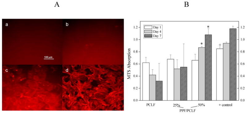
A: Morphology (×200) of rat bone marrow stromal cells on the crosslinked discs 7 days after seeding. (a) PCLF, (b) PPF/PCLF (25%), (c) PPF/PCLF (50%), and (d) tissue culture polystyrene (TCPS). The scale bar of 100 μm in (a) is applicable to all. B: MTS absorption of bone marrow stromal cells on the crosslinked discs of PCLF, PPF/PCLF (25%) and (50%) compared to cell-seeded TCPS as positive (+) control. * p<0.05 between PPF/PCLF (50%) and PCLF or PPF/PCLF (25%). + p<0.05 between tissue culture plate and PCLF or PPF/PCLF at day 1.
As a conditionally immortalized Schwann cell precursor line that myelinates axons,13 SPL201 cell attachment and proliferation results on various surfaces are similar to those for BMS cells. As illustrated in Figure 16A, one drop of condensed cell suspension in medium was seeded onto the center of the polymer discs. After 1 hr cell attachment, more medium was injected into the wells to supply sufficient nutrition. Figure 16B shows SPL201 cell morphology on different polymer discs at different magnitudes. The areas circled by red dots were where cells attached and migrated after a 7-day period. It can be observed that the cell area becomes larger and larger as PPF composition increases, indicating a stiffer surface can support cell migration and attachment better. Photographs (d, e, f) with higher magnification (×200) in Figure 16B shows spread-out cell phenotype and more protruding cellular processes for cell-cell interactions on the disc surface of crosslinked PPF/PCLF (50%). MTS adsorption in Figure 16C demonstrates the cell proliferation in a period of one week for crosslinked PCLF, PPF/PCLF with PPF compositions of 25% and 50%, as compared to cell-seeded TCPS as positive control and TCPS without seeding any cells as negative control. It is evident that PPF/PCLF with 50% PPF can support cell proliferation much better compared to the other two samples with lower compositions of PPF.
Figure 16.
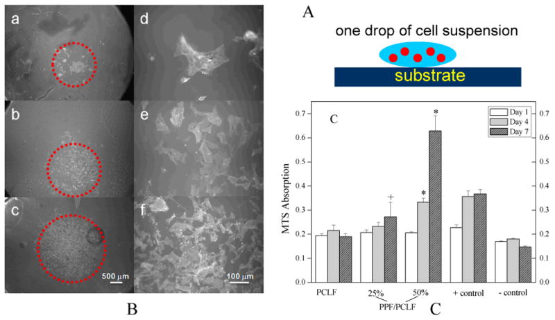
A: Schematic SPL201 cell seeding on the crosslinked polymer discs. B: Morphology (a, b, c: ×25; d, e, f: ×200) of SPL201 cells on the crosslinked discs 7 days after seeding. (a) PCLF, (b) PPF/PCLF (25%), (c) PPF/PCLF (50%), and (d) tissue culture polystyrene (TCPS). The scale bar of 500 μm in (c) is applicable to (a-c) and 100 μm in (f) is applicable to (d-f). C: MTS absorption of SPL201 cells on the crosslinked discs of PCLF, PPF/PCLF (25%) and (50%) compared to cell-seeded TCPS as positive (+) control and empty TCPS as negative (-) control. * p<0.05 between PPF/PCLF (50%) and PCLF, PPF/PCLF (25%), or negative (-) control. + p<0.05 between PPF/PCLF (25%) and PCLF at day 7.
There are three major factors in influencing cell responses on biomaterials: chemical, topological, and mechanical factors.1 The chemical compositions in the blends and the resulting mechanical properties, particularly surface stiffness, vary from sample to sample. As demonstrated in Figure 13, crosslinked PCLF discs have a rougher surface and a higher capability for adsorbing protein than the discs with higher PPF compositions. These characteristics are usually believed to encourage more cell attachment and proliferation.1 Furthermore, a contact angle of ∼50° for crosslinked PCLF is expected to favor cell attachment and proliferation better than a more hydrophobic surface with a contact angle of 90°.1 However, it was just on the contrary in the cell responses using both BMS and SPL201 cell types as demonstrated in Figures 15 and 16. A previous report also found no correlation between the contact angle or protein adsorption and cell adhesion of fibroblast or macrophages, though no further evidence of the role of surface stiffness was revealed.38 Though a better understanding of many unknown factors is needed, surface stiffness can be used as a tentative interpretation for now. The role of surface stiffness was revealed in many other polymeric systems.37 It is believed that probing forces are generated by actin-myosin interactions associated with cell-substrate adhesion sites.37a-c Stiff surface will cause a stronger mechanical feedback and lead to the activation of stress-sensitive ion channels or protein conformational changes, which in turn may regulate the stability of focal adhesions and the strength of contractile forces.37a-c
Material design strategies for biomedical applications involve not only the knowledge about materials chemistry and physics but also biophysics. Despite the efforts in the last several decades, there are still many unknown factors in cell-material interactions. Precisely controlled materials properties are the first step to achieve platforms to understand these factors better. In our laboratory, a series of systematic studies on developing and understanding novel materials for both bone and nerve regenerations have been performed using several UV crosslinked polymeric systems besides the present PPF/PCLF blends. The other polymeric systems include PPF-co-PCL multi-block copolymers with a wide range of PCL composition as well as PPF and PCL block lengths, PCLF series synthesized with different PCL diol precursor molecular weights, and composites consisting of PCLF or PPF and hydroxylapatite nanoparticles. They will be reported subsequently and all the results are consistent with each other in terms of material property roles, particularly the role of surface mechanics in regulating cell responses.
Conclusions
In this study, we supply not only an extensive library of physical properties of the miscible blends of PPF/PCLF, but also a strategy to achieve controllable physical properties for various tissue-engineering applications. In addition to their uncrosslinked counterparts, the UV crosslinking characteristics of PPF, PCLF, and their blends have been investigated extensively in these aspects: chemical structure, gel fraction, swelling properties in different solvents, thermal, rheological, and mechanical properties. By adding PPF into PCLF, the gel fraction increases from 78% for crosslinked PCLF to over 90% for the blends because PPF has a higher double bond density and higher transparency to allow efficient UV crosslinking. The thermal properties can also be well modulated by the introduction of amorphous PPF to semi-crystalline PCLF and further crosslinking. It was found that blending PPF with PCLF can be used as a method to achieve amorphous materials with controllable mechanical properties. The crosslinked samples showed a progressive physical change from a fragile and weak material for crosslinked PCLF to a stiff but brittle material for crosslinked PPF, with a dramatic increase in tensile modulus from 2.08±0.30 MPa for crosslinked PCLF to 1.291±0.004 GPa for crosslinked PPF. Meanwhile, the pull-out force and surface stiffness increase from 0.05±0.01 N and 2.83±0.07 MPa for crosslinked PCLF to 0.71±0.10 N and 33.6±8.9 MPa, respectively, for crosslinked PPF/PCLF blend upon adding 50% PPF. We have evaluated the in vitro cytocompatibility of the photo-crosslinked PPF, PCLF, and their blends using two different cell types, rat bone marrow stromal cells and SPL201 cells, for bone and nerve regeneration, respectively. For both cell types, the photo-crosslinked discs did not show cytotoxicity and the addition of PPF enhanced cell attachment and proliferation on the bare, hydrophobic surface of crosslinked polymer discs in a period of one week, implying the role of surface stiffness in modulating cell responses as the trend cannot be interpreted as the result of surface chemistry such as hydrophilicity and protein adsorption capability.
Supplementary Material
Figure 11.

Storage modulus G′ (solid symbols), loss modulus G″ (open symbols), and viscosity η(line) vs frequency for crosslinked PCLF (↓, circles, and dotted lines) and PPF/PCLF with a PPF composition of 25% (↑, squares, and solid lines).
Acknowledgments
This work was performed at Mayo Clinic with financial support from the Mayo Foundation and National Institutes of Health (R01 AR45871 and R01 EB003060). We thank Mr. James A. Gruetzmacher, Mr. Jarred J. Nesbitt, Dr. Kee-won Lee, and Dr. Theresa Hefferan at Mayo Clinic for technical assistance. We also thank Mr. Mark E. Zobitz at Mayo Clinic for help with pull-out tests and Mr. Zhenqing Li at Clemson University for performing contact angle measurements.
Footnotes
Supporting Information Available: Figure of bone marrow stromal cell viability and SPL201 cell viability for all the crosslinked polymer and blend discs. This material is available free of charge via the Internet at http://pubs.acs.org.
References and Notes
- 1.(a) Harbers GM, Grainger DW. Cell-Material Interactions: Fundamental Design Issues for Tissue Engineering and Clinical Considerations. In: Guelcher SA, Hollinger JO, editors. Introduction to Biomaterials. Boca Raton: CRC Press; 2005. pp. 15–45. [Google Scholar]; (b) Wong JY, Leach JB, Brown XQ. Surf Sci. 2004;570:119. [Google Scholar]; (c) Ross JM. Cell-Extracellular Matrix Interactions. In: Patrick CW, Mikos AG, McIntire LV, editors. Frontier n Tissue Engineering. New York: Pergamon; 1998. pp. 15–27. [Google Scholar]
- 2.Jabbari E, Wang S, Lu L, Gruetzmacher JA, Ameenuddin S, Hefferan TE, Currier BL, Windebank AJ, Yaszemski MJ. Biomacromolecules. 2005;6:2503. doi: 10.1021/bm050206y. [DOI] [PMC free article] [PubMed] [Google Scholar]
- 3.Wang S, Lu L, Gruetzmacher JA, Currier BL, Yaszemski MJ. Macromolecules. 2005;38:7358. [Google Scholar]
- 4.Wang S, Lu L, Gruetzmacher JA, Currier BL, Yaszemski MJ. Biomaterials. 2006;27:832. doi: 10.1016/j.biomaterials.2005.07.013. [DOI] [PubMed] [Google Scholar]
- 5.Wang S, Lu L, Yaszemski MJ. Biomacromolecules. 2006;7:1976. doi: 10.1021/bm060096a. [DOI] [PMC free article] [PubMed] [Google Scholar]
- 6.(a) Peter SJ, Miller MJ, Yaszemski MJ, Mikos AG. In: Handbook of Biodegradable Polymers. Domb AJ, Kost J, Wiseman DM, editors. Harwood Academic Publishers; Amsterdam: 1997. and references therein. [Google Scholar]; (b) Yaszemski MJ, Payne RG, Hayes WC, Langer RS, Aufdemorte TB, Mikos AG. Tissue Eng. 1995;1:41. doi: 10.1089/ten.1995.1.41. [DOI] [PubMed] [Google Scholar]; (c) Yaszemski MJ, Payne RG, Hayes WC, Langer RS, Mikos AG. Biomaterials. 1996;17:2127. doi: 10.1016/0142-9612(96)00008-7. [DOI] [PubMed] [Google Scholar]; (d) Domb AJ, Manor N, Elmalak O. Biomaterials. 1996;17:411. doi: 10.1016/0142-9612(96)89657-8. [DOI] [PubMed] [Google Scholar]; (e) He S, Yaszemski MJ, Yasko AW, Engel PS, Mikos AG. Polymer. 2001;42:1251. [Google Scholar]
- 7.(a) Fisher JP, Dean D, Engel PS, Mikos AG. Annu Rev Mater Res. 2001;31:171. [Google Scholar]; (b) Fisher JP, Holland TA, Dean D, Engel PS, Mikos AG. J Biomater Sci Polymer Edn. 2001;12:673. doi: 10.1163/156856201316883476. [DOI] [PubMed] [Google Scholar]
- 8.Temenoff JS, Mikos AG. Biomaterials. 2000;21:2405. doi: 10.1016/s0142-9612(00)00108-3. [DOI] [PubMed] [Google Scholar]
- 9.Lee KW, Wang S, Lu L, Jabbari E, Currier BL, Yaszemski MJ. Tissue Engineering. 2006;12:2801. doi: 10.1089/ten.2006.12.2801. [DOI] [PubMed] [Google Scholar]
- 10.Lee KW, Wang S, Fox B, Ritman EL, Yaszemski MJ, Lu L. Biomacromolecules. 2007;8:1077. doi: 10.1021/bm060834v. [DOI] [PubMed] [Google Scholar]
- 11.Ng KW, Hutmacher DW, Schantz JT, Ng CS, Too HP, Lim TC, Phan TT, Teoh SH. Tissue Eng. 2001;7:441. doi: 10.1089/10763270152436490. [DOI] [PubMed] [Google Scholar]
- 12.Binaco P, Riminucci M, Gronthos S, Robey PG. Stem Cells. 2001;19:180. doi: 10.1634/stemcells.19-3-180. [DOI] [PubMed] [Google Scholar]
- 13.Lobsiger CS, Smith PM, Buchstaller J, Schweitzer B, Franklin RJM, Suter U, Taylor V. Glia. 2001;36:31. doi: 10.1002/glia.1093. [DOI] [PubMed] [Google Scholar]
- 14.Kharas GB, Kamenetsky M, Simantirakis J, Beinlich KC, Rizzo AMT, Caywood GA, Watson K. J Appl Polym Sci. 1997;66:1123. [Google Scholar]
- 15.Nagata M, Kanechika M, Sakai W, Tsutsumi N. J Polym Sci Polym Chem. 2002;40:4523. [Google Scholar]
- 16.Nagata M, Kato K, Sakai W, Tsutsumi N. Macromol Biosci. 2006;6:333. doi: 10.1002/mabi.200600058. [DOI] [PubMed] [Google Scholar]
- 17.Marcos-Fernádez A, Abraham GA, Valentín JL, San Román J. Polymer. 2006;47:785. [Google Scholar]
- 18.(a) Simha NK, Jin H, Hall ML, Chiravarambath S, Lewis JL. J Biomech Eng. 2007;129:767. doi: 10.1115/1.2768110. [DOI] [PubMed] [Google Scholar]; (b) Hayes WC, Keer LM, Herrmann G, Mockros LF. J Biomech. 1972;5:541. doi: 10.1016/0021-9290(72)90010-3. [DOI] [PubMed] [Google Scholar]
- 19.Woo KM, Chen VJ, Ma PX. J Biomed Mater Res. 2003;67A:531. doi: 10.1002/jbm.a.10098. [DOI] [PubMed] [Google Scholar]
- 20.Engelberg I, Kohn J. Biomaterials. 1991;12:292. doi: 10.1016/0142-9612(91)90037-b. [DOI] [PubMed] [Google Scholar]
- 21.Roovers J, Toporowski PM. Macromolecules. 1992;25:3454. [Google Scholar]
- 22.Chung GC, Kornfield JA, Smith SD. Macromolecules. 1994;27:5729. [Google Scholar]
- 23.Brandrup J, Immergut EH, editors. Polymer Handbook. 3rd. Wiley; New York: 1989. [Google Scholar]
- 24.Fox TG. Bull Am Phys Soc. 1965;1:123. [Google Scholar]
- 25.Herrera D, Zamora JC, Bello A, Grimau M, Laredo E, Müller AJ, Lodge TP. Macromolecules. 2005;38:5109. [Google Scholar]
- 26.Zhang K, Simon CG, Jr, Washburn NR, Antonucci JM, Lin-Gibson S. Biomacromolecules. 2005;6:1615. doi: 10.1021/bm0500648. [DOI] [PubMed] [Google Scholar]
- 27.Gordon M, Taylor JS. J Appl Chem USSR. 1952;2:493. [Google Scholar]
- 28.Brekner MJ, Schneider HA, Cantow HJ. Polymer. 1988;29:78. [Google Scholar]
- 29.Ferry JD. Viscoelastic Properties of Polymers. 3rd. Wiley; New York: 1980. [Google Scholar]
- 30.Anseth KS, Shastri VR, Langer R. Nature Biotech. 1999;17:156. doi: 10.1038/6152. [DOI] [PubMed] [Google Scholar]
- 31.Turunen MPK, Korhonen H, Tuominen J, Seppala JV. Polym Int. 2001;51:92. [Google Scholar]
- 32.Sonmez HB, Wudl F. Macromolecules. 2005;38:1623. [Google Scholar]
- 33.Murugan R, Ramakrishna S. Composites Sci Techn. 2005;65:2385. [Google Scholar]
- 34.Borschel GH, Kia KF, Kuzon WM, Dennis RG. J Surgical Res. 2003;114:133. doi: 10.1016/s0022-4804(03)00255-5. [DOI] [PubMed] [Google Scholar]
- 35.Kavanagh GM, Ross-Murphy SB. Prog Polym Sci. 1998;23:533. [Google Scholar]
- 36.Sperling LH. Introduction to Physical Polymer Science. 3rd. Wiley; New York: 2001. [Google Scholar]
- 37.(a) Discher DE, Janmey P, Wang YL. Science. 2005;310:1139. doi: 10.1126/science.1116995. [DOI] [PubMed] [Google Scholar]; (b) Pelham RJ, Jr, Wang YL. Proc Natl Acad Sci USA. 1997;94:13661. doi: 10.1073/pnas.94.25.13661. [DOI] [PMC free article] [PubMed] [Google Scholar]; (c) Pelham RJ, Jr, Wang YL. Biol Bull. 1998;194:348. doi: 10.2307/1543109. [DOI] [PubMed] [Google Scholar]; (d) Zarri N, Rajagopalan P, Kim SK, Engler AJ, Wong JY. Adv Mater. 2004;16:2133. [Google Scholar]; (e) Lo CM, Wang HB, Dembo M, Wang YL. Biophys J. 2000;79:144. doi: 10.1016/S0006-3495(00)76279-5. [DOI] [PMC free article] [PubMed] [Google Scholar]; (f) Subramanian A, Lin HY. J Biomed Mater Res. 2005;75A:742. doi: 10.1002/jbm.a.30489. [DOI] [PubMed] [Google Scholar]
- 38.Saad B, Keiser OM, Welti M, Uhlschmid GK, Neuenschwander P, Suter UW. J Mater Sci Mater Med. 1997;8:497. doi: 10.1023/a:1018582311361. [DOI] [PubMed] [Google Scholar]
Associated Data
This section collects any data citations, data availability statements, or supplementary materials included in this article.