Abstract
A novel cryogenic heat pipe, oscillating heat pipe (OHP), which consists of an 4 × 18.5 cm evaporator, a 6 × 18.5 cm condenser, and 10 cm length of adiabatic section, has been developed and experimental characterization conducted. Experimental results show that the maximum heat transport capability of the OHP reached 380W with average temperature difference of 49 °C between the evaporator and condenser when the cryogenic OHP was charged with liquid nitrogen at 48% (v/v) and operated in a horizontal direction. The thermal resistance decreased from 0.256 to 0.112 while the heat load increased from 22.5 to 321.8 W. When the OHP was operated at a steady state and an incremental heat load was added to it, the OHP operation changed from a steady state to an unsteady state until a new steady state was reached. This process can be divided into three regions: (I) unsteady state; (II) transient state; and (III) new steady state. In the steady state, the amplitude of temperature change in the evaporator is smaller than that of the condenser while the temperature response keeps the same frequency both in the evaporator and the condenser. The experimental results also showed that the amplitude of temperature difference between the evaporator and the condenser decreased when the heat load increased.
Keywords: Oscillating heat pipes, Cryogenic oscillating heat pipes, Evaporation heat transfer, Convention heat transfer
1. Introduction
When systems operate in a cryogenic environment, effective thermal management becomes one of the most serious challenges. For example, the most common method of heat transport in superconducting magnets is the heat conduction by a copper block. However, with the development of cryocooler-cooled superconducting magnets and large magnets applications, where the heat transport distance is large, the heat conduction by a copper block will be constrained by its cross section transport capacity [1]. In the cryobiology, vitrification of biomaterials using an ultra-high cooling rate is a way to avoid cell damage due to intracellular ice formation (IIF) and exposure to cytotoxic concentrations of solutes. Previous numerical analysis results [2] have shown that to obtain ultra-high cooling rates and uniform cooling temperature fields in cryogenic environments is the key to control the rates x of the ice quantity to the maximum crystallizable ice and improve the cell survival ratio. Therefore, to effectively dissipate the latent heat reserved in the cryopreservation solutions and biomaterials through a long distance in a low temperature environment is a significant challenge. Heat pipes are effective two-phase heat transfer devices, which can transport several orders of magnitude greater heat loads than traditional single-phase techniques, and have been widely used in electronics cooling, spacecraft design and other thermal management systems [3]. Several types of heat pipes, such as the loop heat pipe and the oscillation heat pipe, have the ability to dissipate large heat loads over long distances at low temperatures; and importantly, those heat pipes can provide uniform temperature fields [4,5]. However, the investigation of cryogenic loop heat pipes and oscillating heat pipes have not been widely conducted either theoretically or experimentally. Cryogenic heat pipes reported in the literature can be categorized into four types: thermosyphons [6], wick-based heat pipes [7–9], cryogenic capillary-pumped loops [10] and cryogenic loop heat pipes [1,11,12]. These previous results [11,12] showed that the heat transport capacity of the loop heat pipe with liquid nitrogen as working fluid was very low – only 26W when it operated in a horizontal direction; and its lowest thermal resistance reached 1.3 K/W – which is too high for most of cryogenic heat transport systems.
Akachi [13] pioneered a new device called the oscillating heat pipe (OHP), which utilizes the pressure change in volume expansion and contraction during phase changes to excite the oscillation motion of liquid plugs and vapor bubbles between the evaporator and condenser. Comparing OHP with other conventional heat pipes, the unique feature of OHPs is that there is no wick structure to return the condensate to the evaporator, and therefore there is no countercurrent flow between the liquid and the vapor flows because both operate in the same direction [3]. Other features of OHPs include: (1) the driving force mainly depends on the rate of change in pressure with respect with temperature of working fluid (dp/dT)sat and the temperature difference between the condenser and evaporator. (2) The oscillating motion in the capillary tube significantly enhances forced convection in addition to the phase-change heat transfer, the vapor bubbles and liquid slug formed in capillary tube will effectively produce many thin film surfaces to enhance the phase-change heat transfer both in the evaporating and the condensing heat transfer. Because of these unique features, OHPs have been extensively theoretically and experimentally analyzed investigated in the past several years.
Recently, a new cooling device that combines both the strong oscillating motion in the OHP and the high effective thermal conductivity of nanofluids, which is called a nanofluid oscillating heat pipe, has been developed and experimentally characterized [14]. The nanofluid consisted of high performance liquid chromatography (HPLC)-grade water and diamond nanoparticles (15–50 nm), which the volume ratio of nanoparticles charged to the heat pipe was 1.0% of the base fluid. Experimental results showed that the nanofluid could significantly enhance the heat transport capability in the OHP [14]. Most previous investigations of oscillating heat pipes focused primarily on their operation at ambient temperatures and typically water or acetone was used as its working fluid. In order to better understanding the heat transfer mechanisms and heat transport capacity of cryogenic OHPs, a novel oscillating heat pipe with liquid nitrogen as working flow has been developed and experimentally characterized in this current investigation.
2. Experimental system and cryogenic OHP design
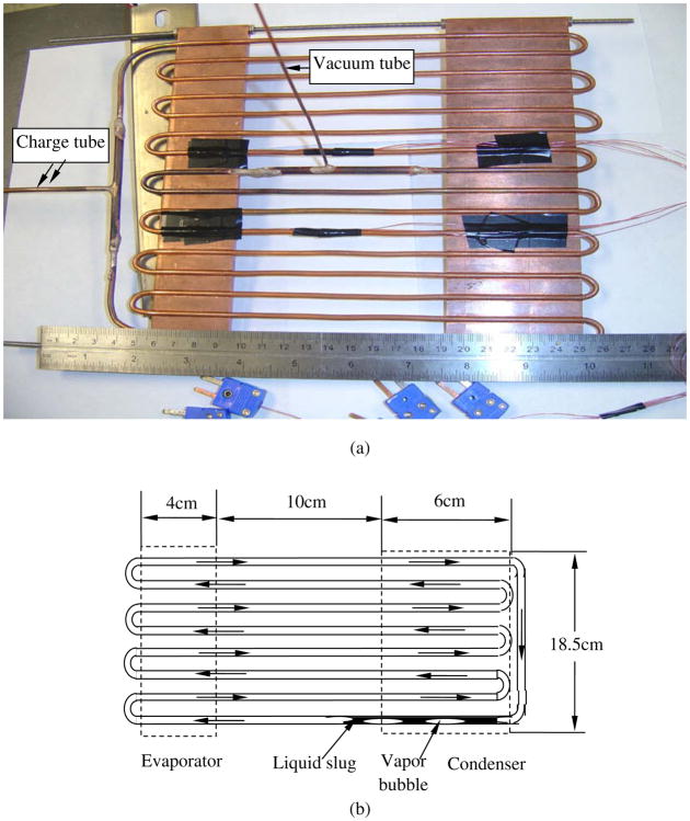
Fig. 1 illustrates the test section, including a schematic of the OHP and a photograph of the OHP prototype. As shown in Fig. 1, the 8-turn closed-loop OHP was developed and manufactured, since the closed-loop OHP has better heat transfer performance [14–16] than that of open loop OPH systems. For a closed-loop OHPs, there exists two moving modes for working flow: (a) an oscillating flow only exist between the evaporator and the condenser; (b) flow along a single-direction moving as shown in Fig. 1b. The OHP was fabricated from alloy 122 copper tubing with an inner diameter of 1.65 mm and an outer diameter of 3.18 mm, which can work very well at 213 atm pressure with T = 37.8 °C and with the pressure change of the cryogenic working fluid at different temperatures. In the design of the OHP, the inner diameter must be small enough so that the surface tension forces dominate gravitational forces and distinct vapor bubbles and liquid slugs can form. The theoretical maximum interior diameter for a capillary tube occurs when the square of the Bond number is less than 4, thus, the critical diameter of the capillary tube can be expressed
Fig. 1.
Test section (OHP): (a) OHP photograph and thermocouples location, and (b) schematic of OHP operation and dimensions.
| (1) |
where, σ is the surface tension, ρl is the liquid density, ρv is the vapor density, and g is the gravitational acceleration. Based on this equation, the copper tubing inner diameter for the current study is well within this constraint. For the working fluid of OHP selection at saturated conditions, a high value of surface tension σ and (dp/dT)sat to create high enough driving force at a given temperature difference between the evaporator and the condenser is important. On the other hand, a low dynamic viscosity to reduce the shear stress along the wall resulting in a low pressure drop in the channel is also desirable. The working fluid of the cryogenic OHP in the current investigation was the liquid nitrogen. A photograph of a test section (cryogenic OHP) is shown in Fig. 1a. The dimensions of the evaporator, where a uniform heat flux was added, were 40 × 185 mm2. In order to improve the heat transfer from the heater to the evaporating section, a 40 × 185 × 5-mm3 copper plate was used. The semicircular grooves machined on the plate created a good fit with the tubing for better heat transfer. The dimensions of the condenser were also 60 × 185 mm2 and it was fashioned in the same manner as evaporator. The distance between the evaporator and the condenser is 100 mm.
Fig. 2 displays the schematic experimental system, which consisted of test section (OHP), data acquisition system, heat input and measurement system, liquid nitrogen pool, and liquid nitrogen tank. The cryogenic OHP (test section), except the bottom surface of condenser, was completely covered by a thick foamed layer, as shown in Fig. 2. The bottom surface of the condenser copper block was directly exposed to the liquid nitrogen pool. The data acquisition system included Type-T thermocouples, an IOtech DAQ/56 USB data acquisition system, and a personal computer to record the temperature response. The type-T thermocouples were calibrated and the total temperature measurement error is less than 0.1 °C. The heat input and measurement system was composed of a heater, its power was supplied by a Staco 3PN501B voltage regulator, and the voltage was measured by a Fluke 45 dual display multimeter (DMM). The electronic resistance (R) of the heater was measured by multimeter at near liquid nitrogen temperatures, since the resistance of the heater depends on the temperature [17]. The heat load was calculated by: P = U2/R; where, U was measured by multimeter and R is the electronic resistance of heater. In the current investigation, the liquid nitrogen pool was contained in an insulated box, which connected with a liquid nitrogen Dewar by a hose.
Fig. 2.
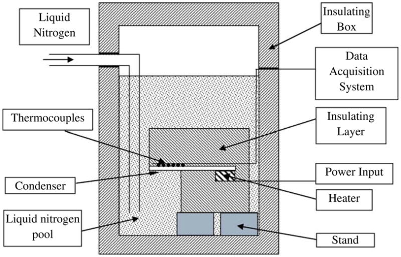
Schematic of experimental system.
Before the start of experiments, the experimental system was pre-cooled until the test section reached the liquid nitrogen saturated temperature since there was not any heat load input. As shown in Fig. 1a, there are two tubes in the OHP, one of them is the charge tube which is directly immerged into the liquid nitrogen pool and the another one (called vacuum tube) is connected to a vacuum pump. In the pre-cooling process, the insulated test section was immerged into liquid nitrogen while the vacuum pump was turned on simultaneously; causing the liquid nitrogen to be flow into the heat pipe. The charge tube and the vacuum tube were closed after the heat pipe was charged enough. The charge ratio is calculated by the weight difference after the experiments. After pre-cooling, the charge process was done until a steady-state condition was reached; the heat load was added to the evaporator by the heater. When the desired steady state was reached at a given heat load, the power was increased incrementally and the operation of OHP was allowed to reach a new equilibrium condition. During the tests, the thermal power input and the temperature data were simultaneously recorded using the IOtech DAQ/56 data acquisition system controlled by a personal computer.
3. Experimental results and discussion
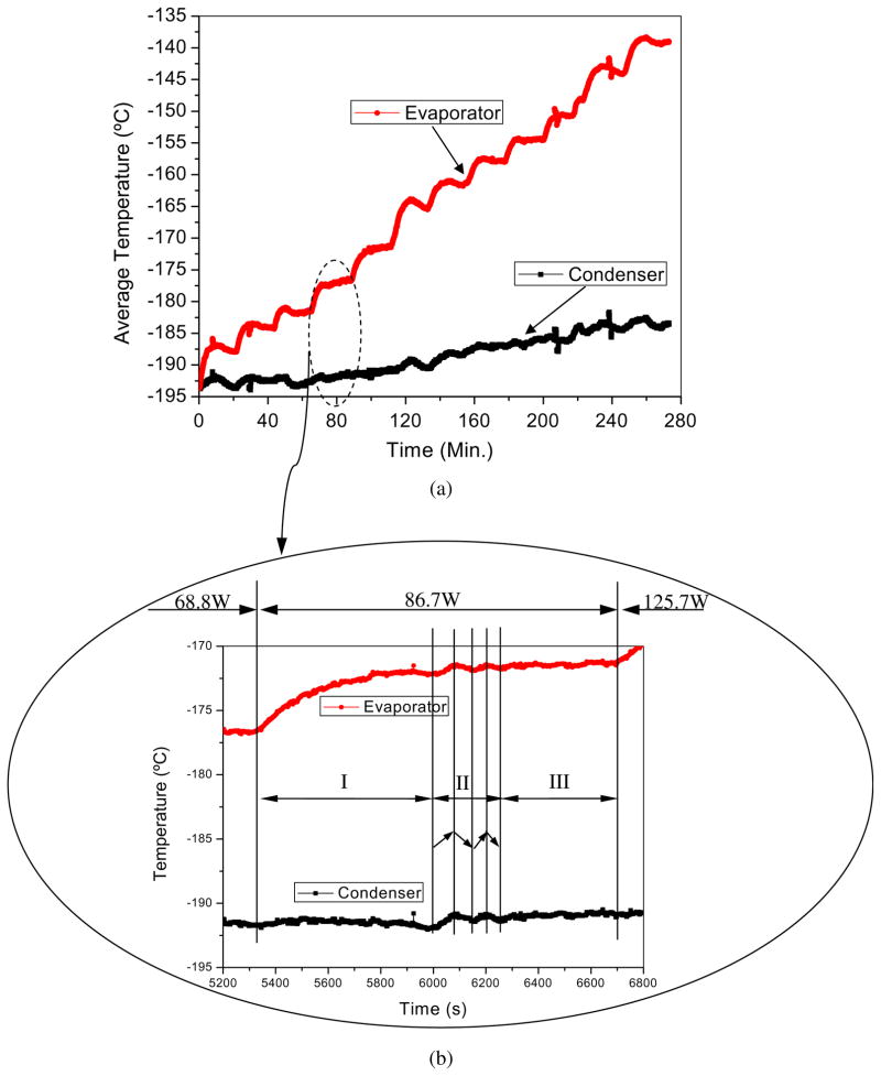
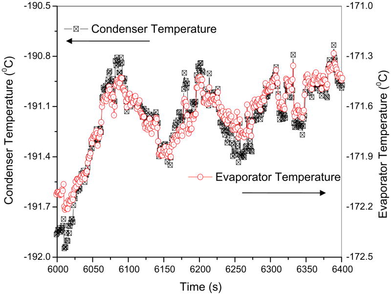
The heat transport performance of the cryogenic OHP with liquid nitrogen as the working fluid and a charge ratio of 0.48 (v/v) were illustrated in Fig. 3. The temperature response of the evaporator and the condenser were displayed in Fig. 3a while the heat loads of the evaporator were changed from 20.5 to 380.1 W. The data acquisition frequency was 1 Hz, for any given heat loads, the OHP operation was recorded at least 21.7 min. As shown in Fig. 3a, the temperature in evaporator changed from the liquid nitrogen saturation temperature (−195.8 °C) to −136.8 °C while the condenser temperature changed from liquid nitrogen saturation temperature to −185.6 °C when the heat load input changed from 20.5 to 380.1 W. In order to show more clearly the temperature response when the heat load was added to evaporator, Fig. 3b showed the evaporator and the condenser temperature response when the heat load was changed from 68.8 to 86.7 W, and then 125.7 W. Obviously, an increment heat load was added, the OPH operation changed from steady state to an unsteady state until a new steady state was achieved, the process can be divided into three regions: (I) an unsteady state (around 12 min), where the change tendency of evaporator temperature is increasing; (II) a transient state (about 4 min), where the temperature of the evaporator and the condenser is unsteady and maintained at the same isochronous pace; the temperature difference between the evaporator and condenser almost kept a constant, and (III) a steady state, where the temperature of the evaporator and condenser has been kept constant. In order to further confirm that the temperature response of the evaporator and the condenser keep the same pace when the heat pipe work at the region II, the temperature response in the evaporator and the condenser is illustrated in Fig. 4 when the time changed from 6000 to 6400 s. As shown in Fig. 4, the temperature responses in the evaporator and the condenser keep the same frequency, however, the amplitudes of the temperature in evaporator are smaller than that of condenser.
Fig. 3.
Temperature responses in the evaporator and the condenser versus heat load: (a) heat load change from 22.5 to 380 W, and (b) heat load 86.7W(I) unsteady state (II) transient state (III) new steady state.
Fig. 4.
Temperature response in the evaporator and condenser reach steady state at Q = 86.7 W.
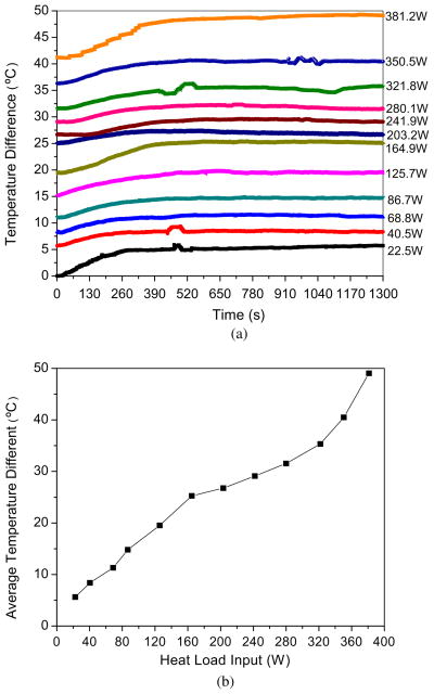
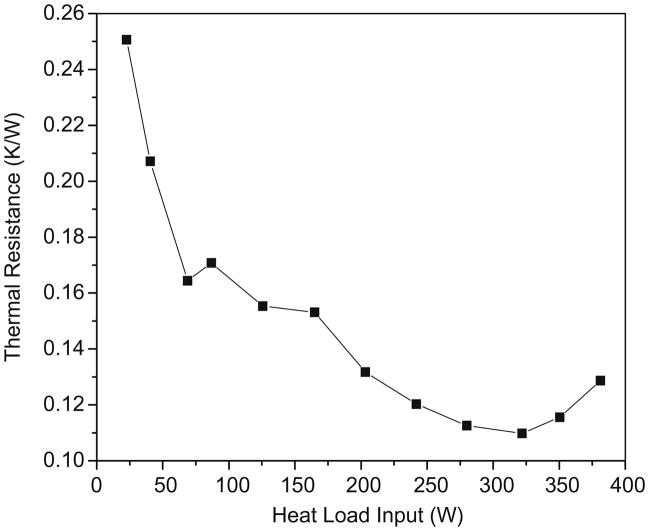
The temperature differences between the evaporator and the condenser as well as the average temperature differences at a steady state are shown in Fig. 5. When the heat load increment was added, the temperature difference changed from an unsteady state to a steady state and reached new equilibrium state within 12 min for any heat load increment. As shown in Fig. 5a, there are several temperature difference changed sharply in the transient state (region II), which should be a result of the working flow moving along a single-direction created in those regions as shown in Fig. 1b. The average temperature difference between the evaporator and the condenser when the OHP was operated at a steady state (after 12 min) has been calculated and shown in Fig. 5b. The average temperature difference varied linearly with the heat load input when the heat load was less than 160 W, and the average temperature difference was a little higher than 25 °C when the heat load reached 160 W. When the heat load continued increasing, the average temperature difference increased very low, for example, the heat load changed from 164.9 to 280.1W (the heat load increment was 115.2 W) while the average temperature difference only increased 6.25 °C. Similarly, the average temperature difference increased 17.5 °C when the heat load changed from 280.1 to 381.2W (the heat load increment was 101.1 W). Therefore, the OHP work at low heat load, the performance is poorer than that work at high heat load. The effective thermal resistance was defined as Reff = ΔTave/Q herein and illustrated in the Fig. 6. As shown in Fig. 6, the effective thermal resistance decreases with the heat load input when the heat load was less than 325 W, however, the effective resistance will increase with the heat load continues increasing. For example, the effective thermal resistances are 0.25 and 0.11 K/W for Q = 22.5, 321.8 W, respectively. The main reason is that the driven force of the oscillating flow in the OHP is the temperature difference between the evaporator and the condenser, the low head load result in a low oscillating flow velocity (low convection heat transfer coefficient). However, the faction of nitrogen gas increase too much in the OHP will decrease the evaporation heat transfer surface (dryout area will increase the thermal resistance sharply) which will affect the heat transfer performance of the OHP when the heat load increment reach some value (limitation), too.
Fig. 5.
Performance of cryogenic OHP with liquid nitrogen as working fluid: (a) temperature difference versus heat load input, and (b) average temperature difference versus heat load input at steady state.
Fig. 6.
Average thermal resistance versus heat load input at steady state.
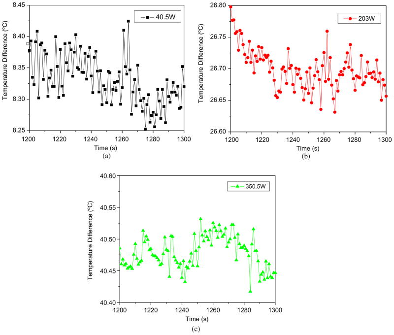
The heat load effect on the amplitude of temperature difference is shown in Fig. 7a–c. As shown in Fig. 7, the amplitude of the temperature difference decreases with the heat load increasing. The sample standard deviation (S) is the unique parameter to evaluate the spread of the temperature difference [18,19], namely, the value of S can be used to stand for the amplitudes temperature difference. The S can be written as:
| (2) |
where, N is the sample size, T̄ is the average temperature of the sample. The values, S, of Fig. 7a–c, are 0.387, 0.313, and 0.025 while the heat load was equal to 40.5, 203, and 350.5 W, respectively. When the higher the heat load added to the evaporator, the higher the temperature difference that will occur between the evaporator and condenser resulting in a large driving force to create higher frequency oscillating flow in the OHP. Higher frequency oscillating flow is equivalent to the higher flow velocity, which results in the high convection heat transfer coefficient while it takes a shorter time to pass through the evaporator and condenser section. Thus, the amplitude of the temperature difference goes down with the heat load increase.
Fig. 7.
Heat load effect on the amplitude of temperature difference at steady state: (a) heat load Q = 40.5 W, (b) heat load Q = 203 W, and (c) heat load Q = 350.5 W.
4. Conclusion
A cryogenic oscillating heat pipe (OHP) has been developed and experimentally characterized. When the OPH is operated in a horizontal direction, the experimental results show that the maximum heat transport capability of the OHP reached 380W with the average temperature difference of only 49 °C between the evaporator and the condenser. The thermal resistance decrease from 0.256 to 0.112 while the heat load increased from 22.5 to 321.8 W. When an incremental heat load was added to it, the OHP operation changed from a steady state to unsteady state till a new steady state reached, the process can be divided into three regions: (I) an unsteady state; (II) a transient state; and (III) a new steady state. The temperature response kept the same frequency both in the evaporator and the condenser when the OHP operated at a steady state, but the amplitude of the temperature change in the evaporator is smaller than that of the condenser. The experimental results also show that the amplitude of temperature difference between the evaporator and the condenser decreases when the heat load increases due to the increase in flow velocity.
References
- 1.Chandratilleke R, Hatakeyama H, Nakagome H. Development of cryogenic loop heat pipes. Cryogenics. 1998;38(3):263–269. [Google Scholar]
- 2.Jiao AJ, Han X, Critser JK, Ma HB. Numerical investigations of transient heat transfer characteristics and vitrification tendencies in ultra-fast cell freezing processes. Cryobiology. 2006;52(3):386–392. doi: 10.1016/j.cryobiol.2006.01.009. [DOI] [PubMed] [Google Scholar]
- 3.Zhang YW, Faghri A. Advances and unsolved issues in pulsating heat pipes. Heat Transfer Eng. 2008;29(1):20–44. [Google Scholar]
- 4.Jiao AJ, Ma HB, Critser JK. Heat transport characteristics in miniature flat heat pipe with wire core wicks. ASME J Heat Transfer. 2008;130:051501. [Google Scholar]
- 5.Jiao AJ, Ma HB, Critser JK. Evaporation heat transfer characteristics of a grooved heat pipe with micro trapezoidal wicks. Int J Heat Mass Transfer. 2007;50(15–16):2905–2911. [Google Scholar]
- 6.Nakagome H, Tanji N, Horigami O, Ogiwara H, Numazawa T, Watanabe Y, Hashimoto T. The helium magnetic refrigerator I: development and experimental results. Advances in Cryogenic Engineering, Proceedings of the Cryogenic Engineering Conference; New York: Plenum press; 1984. pp. 581–587. [Google Scholar]
- 7.Rosenfeld JH, Wolf DA, Buchko MT. Emerging technologies for cryocooler interfaces. Proceedings of the 8th Cryocoolers Conference; New York: Plenum Press; 1995. p. 743. [Google Scholar]
- 8.Eggers PE, Serkiz AW. Development of cryogenic heat pipes. Trans ASME J Eng Power. 1971:1–8. (ASME Publication paper no. 70-WA/Ener-1) [Google Scholar]
- 9.Prenger FC, Stewart WF, Ruyan JE. Development of a cryogenic heat pipe. Adv Cryogenic Eng. 1994;39:1707–1718. [Google Scholar]
- 10.Cullimore B, Krolicaek E, Ku J. Cryogenic capillary pumped loops: a novel cryocooler integration technology. Proceedings of 8th Cryocoolers Conference; New York: Plenum Press; 1995. p. 719. [Google Scholar]
- 11.Mo Q, Liang JT. A novel design and experimental study of a cryogenic loop heat pipe with high heat transfer capability. Int J Heat Mass Transfer. 2006;49:770–776. [Google Scholar]
- 12.Mo Q, Liang JT, Cai JH. Investigation of the effects of three key parameters on the heat transfer capability of a CLHP with insufficient working fluid inventory. Cryogenics. 2007;47:262–266. [Google Scholar]
- 13.Akachi H. 4,921041. US Patent. 1990
- 14.Ma HB, Wilson C, Borgmeyer B, Park K, Yu Q, Choi SUS, Tirumala M. Effect of nanofluid on the heat transport capability in an oscillating heat pipes. Appl Phys Lett. 2006;88:143116. [Google Scholar]
- 15.Gi K, Sato F, Maezawa S. Flow visualization experiment on oscillating heat pipe. Proceedings of the 11th International Heat pipe Conference; Tokyo, Japan. 1999. p. 149. [Google Scholar]
- 16.Zhang XM, Xu JL, Zhou ZQ. Experimental study of a pulsating heat pipe using FC-72, ethanol, and water as working fluids. Exp Heat Transfer. 2004;17(1):47–67. [Google Scholar]
- 17.Jiao AJ, Jeong S, Ma HB. Heat transfer characteristics of cryogenic helium gas through a miniature tube with a large temperature difference. Cryogenics. 2004;44:859–866. [Google Scholar]
- 18.Jiao AJ, Zhang R, Jeong S. Experimental investigation of header configuration on flow maldistribution in plate-fin heat exchanger. Appl Therm Eng. 2003;23:1235–1246. [Google Scholar]
- 19.Jiao AJ, Baek S. Effects of distributor configuration on flow maldistribution in plate-fin heat exchangers. Heat Transfer Eng. 2005;26(4):19–25. [Google Scholar]


