Abstract
Most bacteria and fungi produce low-molecular weight iron-chelators called siderophores. Although different siderophore structures have been characterized, the iron binding moieties often contain catecholate or hydroxamate groups. Siderophores function because of their extraordinarily high stability constants (KSTAB = 1030-1049) and selectivity for Fe(III), yet the origin of these high stability constants has been difficult to quantify experimentally. Herein, we utilise Fe L-edge X-ray absorption spectroscopy to determine the differential orbital covalency (i.e. the differences in the mixing of the metal d orbitals with ligand valence orbitals) of a series of siderophore model compounds. The results enable evaluation of the electronic structure contributions to their high stability constants in terms of σ– and π–donor covalent bonding, ionic bonding and solvent effects. The results indicate substantial differences in the covalent contributions to stability constants of hydroxamate and catecholate complexes and that an increased σ as well as π bonding contributes to the high stability constants of catecholate complexes
Introduction
Siderophores are low molecular weight compounds synthesized by bacteria and fungi to facilitate the uptake of Fe(III),1-3 the concentration of which is severely limited by the extremely low solubility of Fe(III) hydroxide and by iron binding proteins in vivo. Bacterial siderophores occur in three broad groups based on the chemical nature of the chelating ligands: catecholates (e.g. enterobactin4), hydroxypyridonates/hydroxamates (e.g. cepabactin5/ desferrioxamine E6) and aminocarboxylates (e.g. rizoferrin7), all of which act as strong, usually hexa-dentate chelating agents for Fe(III). Because of the importance of biological Fe uptake, significant effort has been directed towards making more efficient ferric chelating agents. Raymond et al.,8-10 have made a number of multi-dentate ligands that incorporate the catecholate and hydroxamate functionalities to mimic the biological sequestering of Fe(III), and these have been used in a number of medical (e.g. oral iron chelation treatment11,12) and industrial (e.g. radionuclide separation13,14) applications. Understanding the factors leading to the high stability and Fe(III) selectivity of the siderophores has important implications in controlling Fe transport in biology and may lead to the design of more effective chelating agents.
The high binding constants have enthalpic (covalent and ionic contributions to bonding as well as solvent effects) and entropic contributions. The formation constants for a large number of hexa-dentate siderophores and bidentate model compounds are known.4,8,10 The stability constant of [Fe(cat)3]3− (cat=catecholate) is 1044.9 and that of the hexadentate catecholate based enterobactin is Kf=1049; that of the tris-hydroxamate compound [Fe(aha)3] (aha− =acetohydroxamate) is 1028.33 and that of the hexadentate tris-hydroxamate complex ferrioxamine B is 1030.6. Thus both the catecholate and hydroxamate bidentate ligands make a significant contribution to the overall binding constants of the siderophores. For comparison, the stability constant15 of the tris bidentate oxalate to form [Fe(ox)3]3− is 1018. The bonding contributions to these differences in stability constants have been difficult to experimentally quantify.
Siderophores are generally brightly colored, due to low energy ligand to metal charge transfer transitions which reflect the very covalent nature of the ligand-metal bonds. In an earlier study,10 we assigned these charge transfer bands in [Fe(cat)3]3− and could identify that the system had more π donation than, for example, the analogous oxalate compounds, where LMCT transitions are absent at low energy. However, the magnitudes of π-donation and the relative magnitudes of π-donation to σ-donation cannot be extracted from charge transfer bands.
Recently, a methodology has been developed based on L-edge X-ray Absorption Spectroscopy coupled to multiplet simulations that enables the determination of the covalent delocalization of the different symmetry sets of d-orbitals, called differential orbital covalency (DOC).16 The Fe L-edge, 2p → 3d transition is electric dipole allowed with the 2p orbital localized on the Fe. This means that the Fe L-edge intensity is directly proportional to the Fe d-character in the valence orbitals on the metal and thus the % metal character in the d orbitals can be probed by the integrated L-edge intensity.16-19 For systems where there is no back-bonding, a lower % metal character indicates a system that is more covalent. The shape of the spectrum permits insight into the ligand field, but is complicated by multiplet contributions similar to the effects described by the Tanabe Sugano20 matrices and diagrams for dN metal complexes, but for the 2p53dN+1 final states that also includes p-d electron repulsion and spin-orbit coupling. A further contribution to the L-edge shape is the effect of differential orbital covalency. The effect of the differences in covalency on the different d orbitals is now well understood in the case of Fe(III) low spin complexes where a distinct “t2g feature” is present on the low energy side of the L-edge spectrum. The intensity of the “t2g feature” relative to the “eg feature” (a set of final state multiplets derived from the 2p53d(t2g5eg1) configuration) further reflects the relative covalencies of the two symmetry sets of d orbitals. Here, we study Fe L-edge XAS spectra of a series of high spin compounds where the ligand field splitting is smaller than the electron-electron repulsion. This leads to a greater mixing of states distributing the σ and π covalencies over the multiplets constituting the L-edge spectrum. It is found that the σ and π contributions can still be quantified experimentally from the spectral shape and correlated to DFT calculations, providing insight into electronic structure contributions to the high stability constants of the siderophores. The metal binding mode of each of the ligands included in this study as well as bond lengths in Å, are given in Scheme 1.
Scheme 1.
Model compounds included in this study, key distances are shown in Å.21
Experimental
Sample Preparation
[Fe(pha)3] and K3[Fe(cat)3] (where cat= catecholate and pha is propyl-hydroxamate) were synthesized according to published methods.22,23
XAS Data Collection
X-ray absorption spectra were recorded at the Stanford Synchrotron Radiation Laboratory (SSRL) on the 31-pole wiggler beam line 10-1 and bending magnet beam line 8-2 (Fe L-edges), and on bending magnet beam line 2-3 (Fe K-edges) under ring operating conditions of 70-100 mA and 3 GeV. Details of the beam line optics have been described previously.16,24 For Fe L-edge measurements the samples were finely ground and spread across double-sided adhesive conductive graphite tape and attached to a copper paddle, aligned 45° to the incident beam under an inert atmosphere.25 All measurements were made at 20±5°C. The energy was calibrated from the Fe L-edge spectrum of Fe2O3, run at intervals between scans. The second feature in the L3 and the first feature in the L2 edges were calibrated to 708.5 and 720.1 eV, respectively. Data were taken over the range 670-830 eV to permit normalization, as described previously.16 A step size of 0.1 eV was used over the edge region (700-730 eV), and 0.5 eV steps over the remaining regions. Two arc tangents were subtracted from the spectra: absorption = [tan−1(k(energy-I1)+π/2)*2/3*1/π] + [tan−1(k(energy-I2)+π/2)*1/3*1/π] where k=0.295 was obtained from the experimental fit16,26 and I2=I1+12.3 eV (where I2 is the energy of the L2 feature relative to that of I1 of L3, split by spin orbit coupling) was used to model the L3 and L2 edge jumps, as described previously.16 The error reported represents the range of integrated intensity, based on at least three repeat measurements of the same spectra on different dates. For Fe K-edges the sample was mixed with boron nitride and ground into a fine powder. The powder was loaded into a 1-mm thick Al spacer and sealed with 63.5 μm Kapton tape windows. Fe K-edges were measured in transition mode with N2-filled ionization chambers to k=9.5 Å−1. A total of 2-3 scans were measured per sample to ensure reproducibility. Energies were calibrated against the first inflection point at 7111.2 eV of an internal foil standard.27 A 2nd order polynomial was fit to the pre-edge and subtracted from the data. A two-segment spline of order two was fit to the EXAFS region and all data were normalized to the edge jump at 7130 eV.
Ligand Field Multiplet Calculations
Calculations were performed using the multiplet model implemented by Thole,28 which employs the atomic theory code developed by Cowan,29 and the crystal field (i.e. symmetry) code developed by Butler.30 This approach includes both electronic Coulomb interactions and spin-orbit coupling for each sub-shell. To simulate the spectra, the Slater-Condon-Shortley parameters (Fi and Gi) were first reduced to 80% of their Hartree-Fock calculated values to account for the over-estimation of electron-electron repulsion found in ab initio Hartree Fock calculations of the free ion. The spectrum is calculated from the sum of all possible transitions for an electron excited from the occupied 2p level into an unoccupied 3d level. In the crystal field limit the ground state is given by a single electronic configuration dN (where, N = the number of valence d electrons) split in energy by electron repulsion and a ligand field potential in Oh symmetry. The ligand field splitting of the d orbitals is estimated from DFT calculated ground-state energies and eigenfunctions.
Covalent mixing of the metal valence d orbitals with the ligand valence p orbitals was included using a charge transfer model which in the case of ligand-to-metal charge transfer (LMCT) adds a dN+1L configuration (L indicates a hole on the ligand) energetically above the dN ground configuration (by an energy separation Δ). The two states are coupled by configuration interaction (CI), represented by the mixing term Ti = <3dN|h|dN+1L> where h is the molecular Hamiltonian and Ti is proportional to metal-ligand overlap for each of the i symmetry blocks. For a donor ligand system the ground and LMCT states are ψGS,B = α1|3dN> + β1|3dN+1L> and ψGS,AB = β1|3dN> − α1|3dN+1L> and the L-edge excited states are ψES,B = α2|2p53dN+1> + β2|2p53dN+2L> and ψES,AB = β2|2p53dN+1> − α2|2p53dN+2L>, where the coefficients α1, α2, β1, β2 are a function of T and Δ for the ground state and T and Δ′ for the excited state, where Δ′ = ΔGS+U−Q, and U is the 3d-3d electron repulsion and Q is the 2p-3d repulsion. To simulate the spectra, first the combination of ligand field and multiplet effects was considered, then σ- and π-donation were explicitly included by ligand to metal charge transfer (LMCT) simulations.
In order to determine the DOC, the projection method of reference 16 was applied to the simulated spectrum. This method uses the TT-multiplets program to split the intensity of the spectrum into its different symmetry components via 4s→4p dummy transitions. These values are then degeneracy weighted to obtain the experimental DOC.
DFT Calculations
The starting structures of the compounds [Fe(cat)3]3−, [Fe(aha)3], [Fe(ox)3]3−, [Fe(F)6]3− (used as a reference for the stability constants, vide infra) were taken from the crystal structures of K3[Fe(cat)3].2H2O,23 [Fe(aha)3].2H2O,31 K5Na[Fe(ox)3]2,32 and [C(NH2)3]3[Fe(F)6],33 respectively. DFT calculations were performed using both the ADF 2003 program34-36 and Gaussian03 (revision C.01).37 In ADF, the geometries were optimized using the exchange functional of Becke38 and the correlation functional of Perdew (BP86).39 The frozen core approximation40 was used for the iron 1s-2p orbitals. For valence orbitals, Slater-type orbital (STO) basis sets of triple-ζ quality were employed with polarization functions on the ligand atoms (3d) and additional valence p orbitals on the metal atoms. i.e. ADF basis set IV.35,36,41 This basis set combination has been shown to give a well converged solution.42,43 Mulliken population analysis was performed as implemented by ADF.34 Orbital plots were generated using G-OpenMol Version 2.2.44 Inplicit solvation was applied in ADF, using the COnductor-like Screening MOdel (COSMO).33-35 Nonbonded radii used (in Å) were N ) 1.608, H ) 1.350, C ) 1.700, O ) 1.517, and Fe ) 1.750. A dielectric constant of 78.8 (water) and an outer cavity radius of 1.9 Å were further used to parametrize the COSMO solvation cavity.45-47 For comparison, this process was repeated in Gaussian03 using the B3LYP exchange-correlation functional with the triple-ζ 6-311G** basis set, and the Polarized Continuum model for solvation.48-50 Molecular orbital (MO) compositions and overlap populations between molecular fragments were calculated using the AOMix program51-54 or the QMForge (PyMolyze) program.55
To calculate stability constants, optimized geometries of all the components of the reaction were calculated using the B3LYP hybrid exchange-correlation functionals with the triple-ζ 6-311+G* basis set. This functional and basis set combination was found to reproduce the crystal structure of the model complexes and was used for further calculations. Total energies were obtained by single-point calculations on these structures using the B3LYP hybrid functional but with a larger 6-311++G** basis set. This improvement of the basis set did not change the energies by more than 1 kcal.mol−1. Tight SCF convergence criteria (10−8 a.u.) were used for all calculations. Frequency calculations were performed to ensure that stationary points were minima. The molar entropy, enthalpy and Gibbs free energy of reaction at 298 K and at a pressure of 1 atm were calculated using standard statistical mechanics formulas.56
Results
Spectroscopy
A. Fe K-edge Spectra
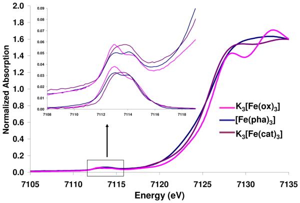
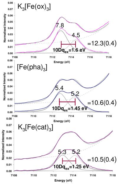
Figure 1 shows the normalized Fe K-edge spectra of K3[Fe(ox)3], [Fe(pha)3]21 and K3[Fe(cat)3]. The energy shift of the rising edge follows the trend K3[Fe(cat)3]< [Fe(pha)3] < K3[Fe(ox)3]. An expansion of the energy region 7109-7119 eV is given in the inset, along with the background subtracted pre-edges. In all cases, the pre-edge spectra were fit with two pseudo-Voigt functions, Figure 2, Table S1. The energy difference between the two peaks follows the trend K3[Fe(cat)3]< [Fe(pha)3]< K3[Fe(ox)3]. The pre-edge intensities of the three compounds are slightly different, with that of oxalate being 1.8 units more intense than hydroxamate and catecholate complexes, and with the difference in intensity predominantly coming from the lower energy peak.
Figure 1.
Comparison of the Fe K-edge data for the compounds K3[Fe(ox)3] (data from reference 25), [Fe(pha)3] and K3[Fe(cat)3]. The inset expands the pre-edges, top = experimental data and lower = background subtracted data.
Figure 2.
Fits to the Fe K pre-edge data for K3[Fe(ox3)], [Fe(pha)3] and K3[Fe(cat)3]. In each frame the upper spectrum (colored) shows the data, lower spectrum shows the background subtracted fit to data.
B. Fe L-edge Spectra
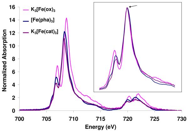
Figure 3 shows the normalized Fe L-edge spectra of K3[Fe(ox)3], [Fe(pha)3] and K3[Fe(cat)3]. The inset compares the three spectra shifted in energy and scaled so that the main feature of each is superposed. The change in total intensity corresponds to a change in the total metal d character in the unoccupied orbitals which increases across the series: K3[Fe(cat)3] 65(5) < [Fe(pha)3] 68(5) < K3[Fe(ox)3] 84(5), Table 1. The superimposed spectra (Figure 3, inset), show a systematic change in shape. The intensity of the lowest energy spectral feature increases across the series: K3[Fe(cat)3] < [Fe(pha)3] < K3[Fe(ox)3] such that the ox spectrum has the two most pronounced features, and in the catecholate spectrum the first feature is shifted up in energy and decreased in intensity to a shoulder on the main peak.
Figure 3.
Normalized Fe L-edge absorption spectra for the compounds: K3[Fe(cat)3], [Fe(pha)3] and K3[Fe(ox)3] (data from reference 16). Inset shows the three spectra shifted in energy to superimpose and scaled to the same intensity on the main peak, arrow.
Table 1.
Summary of Fe L-edge data for the series of compounds K3[Fe(ox)3], [Fe(pha)3] and K3[Fe(cat)3]
| L3 Intensity 702-717 eV |
Intensity weighted average energy (L3) |
L2 Intensity 717-727 eV |
Intensity weighted average energy (L2) |
Branching ratio 57 I(L3)/ I(L2+L3) |
Average% d character in unoccupied orbitals± |
|
|---|---|---|---|---|---|---|
| K3[Fe(ox)3] | 41.6 | 709.4 | 10.4 | 721.7 | 0.80 | 84(5) |
| [Fe(pha)3] | 33.6 | 708.9 | 7.9 | 721.4 | 0.81 | 68(5) |
| K3[Fe(cat)3] | 31.3 | 709.2 | 7.9 | 721.3 | 0.80 | 65(5) |
Note that the % metal d character is inversely proportional to the covalency.
Analysis
A. Fe K-edge Spectra
The Fe K pre-edge spectra of high spin FeIII compounds in Figure 2 show two peaks that reflect Fe1s→3d transitions producing 5T2, and 5E states (which equivalently couple to the (1s)1, 2S core hole) split by an excited state 10Dq (10Dqex).24 The magnitude of 10Dqex decreases across the series [Fe(ox)3]3− (1.60 eV) > [Fe(pha)3] (1.45 eV) > [Fe(cat)3]3− (1.25 eV) consistent with an increase in π donation or a decrease in σ donation (however, the σ donation in fact increases vide infra). The values of 10Dqex are smaller than those values obtained from optical data for [Fe(cat)3]3− (1.30 eV)10 and [Fe(ox)3]3− (1.75 eV),58 consistent with observations by Cramer et al.59 that 10Dqex is smaller than 10Dq of transitions within the ground configuration. From Figure 2 the intensity of the K3[Fe(ox)3] spectrum is 1.8(0.4) units higher than those of the [Fe(pha)3] and K3[Fe(cat)3] compounds, with the difference being predominantly attributable to the first feature (5T2). There are two mechanisms for intensity at an Fe K pre-edge. The first is the direct quadrupole allowed transition to the Fe3d orbitals, whose intensity is affected by covalency. The second is the electric dipole transition to the small amount of Fe4p character mixed into the Fe3d orbitals which increases with deviations from centrosymmetry.24 It has been shown that for Fe(III) ~6-7 units of intensity are due to the to the quadrupole allowed Fe1s→3d character with the remainder of the pre-edge intensity being attributed to the electric dipole allowed Fe1s→4p character. All three compounds studied here have O-Fe-O angles of 80 degrees (Scheme 1) and the 4p mixing is calculated to be similar, (~0.5 % from the calculations presented in Section 3) indicating the higher intensity in oxalate relative to catecholate and hydroxamate is attributable to differences in valence metal d-character, with the oxalate complex having a higher % metal d character, therefore being less covalent. The difference in intensity of the first feature relative to the second when comparing oxalate to catecholate and hydroxamate is consistent with the trends in 10Dqex and indicates that the π (t2g) covalency difference of the series is larger than that of the d σ(eg) orbitals.
B. Fe L-edge
1. Total Intensity and Energy
Three aspects of Fe L-edge spectra are a consequence of bonding: total intensity, energy shift and spectral shape. Comparing the compounds K3[Fe(ox)3] → [Fe(pha)3] → K3[Fe(cat)3], the total intensity decreases (Table 1), indicating that the average ligand character therefore covalency of the unoccupied metal d based orbitals increases. Metal L-edge energy shifts reflect three contributions: the charge on the absorbing metal atom in the molecule, the ligand field splittings of the d orbitals, and any difference in the nature of the ligand valence orbitals. The last contribution is important where metal character mixed into low lying π* ligand-based orbitals due to back-bonding will increase the intensity and change the energy/intensity distribution of a spectrum.60,61 In the case of high spin Fe(III), the contributions of the ligand field should be negligible as the degeneracy weighted average energy of the d orbitals is zero. As there will also be no spectroscopic contribution from π* orbitals for the donor ligands studied herein, we expect little energy shift, and indeed the intensity weighted energies of the L-edge spectra of these complexes are within error the same (Table 1). Note that this is in contrast to low spin ferric systems where an energy difference of up to 1.4 eV due to the ligand field is observed.60
2. Spectral Shape
The L-edge spectral shape has three contributions: electrostatic multiplet effects, ligand field effects, and differential orbital covalency (DOC). These will be systematically evaluated below for these high spin FeIII complexes.
2.1 Multiplet and Ligand Field Effects on Spectral Shape
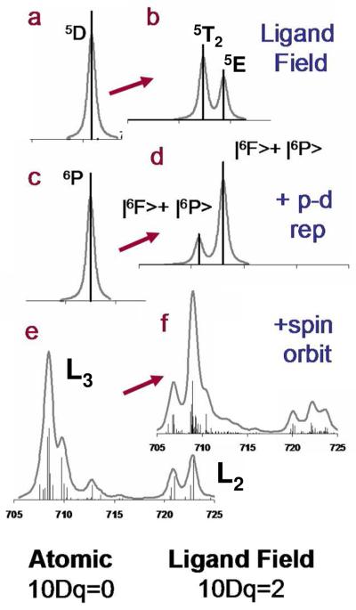
In the absence of covalency the spectral shape has contributions from d-d repulsion, p-d repulsion, spin-orbit coupling, and the ligand field splitting of the d orbitals. The effect on the Fe L-edge of each of these contributions is given in Figure 4. The first spectrum a) shows the single state that would result when no multiplet effect is present; b) shows the spectrum which results from the effect of an Oh ligand field on high spin Fe(III) i.e. two peaks in the intensity ratio of 3:2. These are the 5T2 and 5E states on the weak field side of a d6 final state Tanabe Sugano diagram, (no coupling to the 2P (2p5) core hole). Spectra c and d take into account the 2p core hole (2P). When this is coupled with the 5D (3d6 free ion term symbol), three sextet states arise, 6F + 6D + 6P, and only the transition to the 6P is electric dipole allowed from the 6S ground state. However, with an Oh ligand field (Figure 4, c→ d) the 6F state mixes with the 6P because both of these states have a T1 symmetry component (Table 2). The energy separation of these two states is a function of p-d repulsion and to some extent the magnitude of the ligand field. At low 10Dq there is little intensity in the 6F state and the two states are separated by p-d repulsion (1.2 eV). However, as 10Dq gets large, the splitting of these two states becomes dominated by 10Dq. Upon the addition of spin orbit coupling the states split further, however, the shape and separation of the |6F> and |6P> dominate the L3 and L2 spectral shape (Figure 4f). Note that of the two contributions to spin orbit coupling, the 2p dominates, Figure S4.
Figure 4.
Systematic inclusion of multiplet contributions to the L-edge spectrum of high spin Fe(III), left for free ion, right for Oh metal complex. a and b show the spectra in the absence of spin-orbit or p-d repulsion, c and d include the effects of p-d repulsion,62 and e and f also include spin orbit coupling, from L3, J=3/2 and from L2, J=1/2.
Table 2.
Free Ion →Oh complex.
| O | |
|---|---|
| S | A1 |
| P |

|
| D | E + T2 |
| F |

|
2.2 Systematic Evaluation of 10Dq
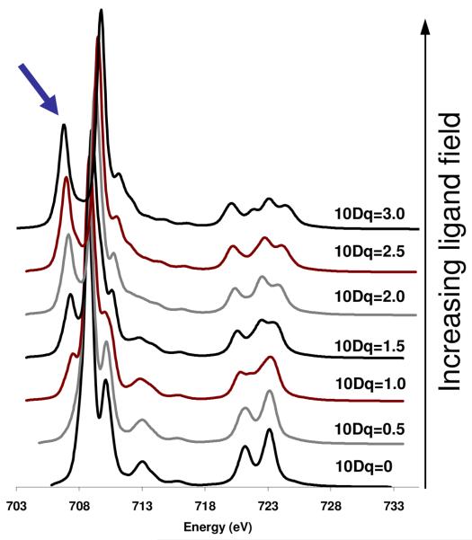
Figure 5 shows the effect of systematically increasing 10Dq from the atomic limit (10Dq=0 eV) to 10Dq=3.0 eV, all complexes having a high spin ground state. It is clear that as 10Dq is increased, the spectra get broader and begin to take on features analogous to those in Figure 4f. A prominent feature that appears as 10Dq increases is the peak on the low energy side of the L3 indicated by the arrow in Figure 5.
Figure 5.
The calculated effect of ligand field on the spectrum of high spin Fe(III) complex. Top spectrum has 10Dq=3.0 eV; the bottom spectrum has 10Dq=0. Arrow indicates the prominent low energy feature that appears as 10Dq increases.
While the compounds studied here are D3 distorted from Oh, the distortions are small relative to the other contributions to the state splitting and do not impact on spectral shape.10 The difference between Oh symmetry simulations and low symmetry simulations is given in Figure S5.
2.3 Differential Orbital Covalency
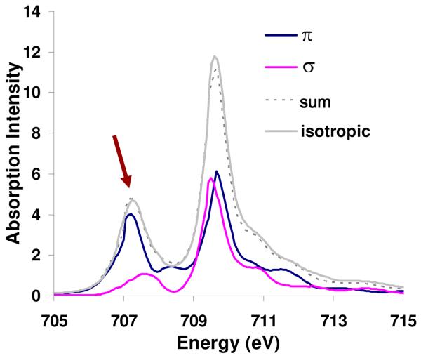
In order to determine the difference in π and σ d character distributed over the L-edge, the spectrum in Figure 6 (10Dq = 1.8 eV but now including equal amounts of σ and π covalency) was generated (Figure 6, isotropic spectrum, grey). Further spectra were generated with only π covalency and only σ covalency, but with 80% total hole weighted orbital covalency. These spectra are shown in Figure S2. These spectra were subtracted and renormalized to obtain pure π (Figure 6, blue) and σ (Figure 6, pink) density of state distributions across the high spin Fe(III) L-edge spectrum. This methodology is presented in more detail in the Supporting Information.
Figure 6.
σ and π density of states for an Oh Fe(III) high spin L3-edge with 10Dq=1.8 eV.
While both the σ and π contributions are clearly distributed over all parts of the L-edge, there is a higher proportion of “π” relative to “σ” character in the low energy feature (arrow, in Figure 6). This difference in distribution enables a determination of the differential orbital covalency. A stronger π contribution to bonding will lead to lower intensity in the first feature relative to the large peak at 710 eV.
2.4 Fits to Data
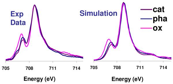
From the experimental spectra given in Figure 3, in going from [Fe(ox)3]3− to [Fe(pha)3] to [Fe(cat)3]3− the first feature decreases in intensity relative to the second and the two peaks are shifted closer together. From the above analysis this is indicative of a decrease in 10Dq and an increase in π-donation. The simulations of the experimental data are given in Figure 7 and compared to the experimental spectra (full simulations including the L2 pre-edge are given in Figure S3). The dominant parameter that needed to be varied to simulate the spectral changes was the t2g mixing (π donation), however a decrease in 10Dq across the series was also necessary (Table 3). To interpret the simulations in terms of experimental estimates of molecular orbital coefficients it is necessary to project the symmetry components as described previously.16 The results of these projections are given in Table 4, columns 4-6. The experiment shows a substantial increase in π- donation across the series; from limited π donation in ferric tris oxalate (6%) to substantial π donor character in ferric catecholate (26%) (Table 4). The σ covalency also increased particularly in the catecholate system.
Figure 7.
Comparison of VBCI simulation and experiment (inset in Figure 1) for Fe L3 edge of the series K3[Fe(ox)3], [Fe(pha)3] and K3[Fe(cat)3].
Table 3.
Parameters used in VBCI simulations. EG2 is the separation of the two lowest energy states in each configuration in the ground/initial state; EF2 is this separation in the final state. Δ0 is the weighted average energy separation of these states in the initial state. T(eg) and T(t2g) are the mixing terms (vide supra).
| Spectra | EG2 | EF2 | Δ 0 | T(eg) | T(t2g) | 10Dq |
|---|---|---|---|---|---|---|
| K3[Fe(ox)3] | 1 | −1 | 1.51 | 1.8 | 0.8 | 1.5 |
| [Fe(pha)3] | 1 | −1 | 1.45 | 2.0 | 1.2 | 1.3 |
| K3[Fe(cat)3] | 0 | −2 | 0.27 | 1.6 | 1.0 | 1.3 |
Table 4.
Summary of L-edge integrated intensity, average experimental covalency (given as d character in unoccupied orbitals), Differential Orbital Covalency (DOC) and DFT calculations.
| Species | Intensity | Average % d character in unoccupied orbitals± |
Projected experimental covalency |
DFT (BP86)** | DFT (B3LYP) 63 | ||||||||
|---|---|---|---|---|---|---|---|---|---|---|---|---|---|
| Fe (t2g) π |
Fe (eg) σ |
D O C |
avg | Fe (t2g) |
Fe (eg) |
D O C |
avg | Fe (t2g) |
Fe (eg) |
D O C |
|||
| [Fe(ox)3]3− | 53.3(4.0) | 84(5) | 94 | 69 | 25 | 72 | 80 | 61 | 19 | 80 | 88 | 69 | 19 |
| [Fe(pha)3] | 43.1(3.6) | 68(5) | 72 | 61 | 11 | 62 | 63 | 60 | 3 | 70 | 74 | 64 | 10 |
| [Fe(cat)3]3− | 41.2(3.1) | 65(5) | 74 | 52 | 22 | 56 | 62 | 46 | 16 | 63 | 74 | 50 | 24 |
Note that the % metal d character is inversely proportional to the covalency.
3. Comparison to DFT
3.1 Geometry Optimization
Geometry optimizations of all compounds were performed using BP86 and B3LYP. The geometric structure parameters are compared to experiment in Table S2. In general, the optimized structures agree well with the experiment, however, the Fe-O bond lengths are uniformly too long across the series of compounds, consistent with what has been noted elsewhere.64,65
3.2 Differential Orbital Covalency
Table 4 compares the calculated values of total orbital covalency and differential orbital covalency to experiment. The trends in total orbital covalency are oxalate→hydroxamate→catecholate: experiment (% d character) (84 → 68 → 65); B3LYP (80 → 70 → 63); BP86 (72 → 62 → 56). These indicate that the magnitude of the trend is better reproduced with the B3LYP hybrid functional, as BP86 describes the complexes as overly covalent. The analogous comparisons for DOC (difference in π vs σ contribution) oxalate→hydroxamate→catecholate are: experiment (25 → 11 → 22); B3LYP (19 → 10 → 24); BP86 (19→ 3 → 16). These also indicate a better agreement between experiment and the B3LYP calculation.
3.3 Stability Constants
As the B3LYP calculations gave electronic structure descriptions most consistent with experiment, these were chosen for further analysis of stability constant data. The experimental numbers for the tris-ligand binding to [Fe(H2O)6]3+ are 1044.9 for [Fe(cat)3]3− 66,67, 1028.3 for [Fe(aha)3],68 and 1018.49 for [Fe(ox)3]3−.68 These are corrected for pKa effects and are therefore appropriate for comparison. Calculations of [Fe(H2O)6]3+ are complicated by intramolecular H-bonding effects due to modelling in a PCM and therefore [FeF6]3− was chosen as a reference. In order to compare the calculated thermodynamic values to experiment, the measured stability constants of the reactions referenced against [Fe(H2O)6]3+ were converted to [FeF6]3− as a reference (1015.04) giving the ratios in Table 5, column 2, ref 21. The calculations in solvent (next to last column) reproduce the experimental trends in stability constants with the ΔG of hydroxamate being ~10 kcal/mol more negative than for oxalate, and that of catecholate being ~20 kcal/mol more favourable than hydroxamate. The TΔS components giving the entropic contributions do not vary much across this series of compounds. Thus, the differences in ΔG across the series are dominantly due to the ΔH contributions to bonding and are examined below.
Table 5.
Comparison of calculated and experimental thermodynamic parameters values in water unless otherwise indicated.
| KSTAB(exp) [FeF6]3− + 3L ↔ [FeL3]+ 6F− |
ΔG(exp) 298 K |
ΔH(calc) | TΔS(calc) | ΔG(calc) 298 K |
ΔG (calc, gas phase) 298 K |
|
|---|---|---|---|---|---|---|
| [Fe(ox)3]3− /[Fe(F)6]3− |
1018.49/1015.04 | −4.6 | 17.3 | 10.1 | 7.2 | 67.4 |
| [Fe(aha)3]3−/ [Fe(F)6]3− |
1028.33/1015.04 | −18.14 | 8.8 | 12.3 | −3.4 | 193.0 |
| [Fe(cat)3]3−/ [Fe(F)6]3− |
1044.9/1015.04 | −40.8 | −18.4 | 6.5 | −25.0 | 38.4 |
Gas phase values for ΔG are given in the final column of Table 5. The trend between oxalate and catecholate is similar in both the solvent and gas phase calculations. Therefore, this difference between oxalate and catecholate binding is dominated by differences in the ionic and covalent contributions to bonding. To examine the ionic contribution NPA charge distributions were calculated in both the gas and solvated phase (Table 6). From the NPA charge distributions, oxalate has a slightly larger ionic term than catecholate. Therefore, the difference in ΔG has its origin in the difference in covalent contributions to bonding revealed by the L-edge data in Figure 3 and Table 4 i.e. the high π and σ covalency of the cat-Fe(III) bond relative to ox. An examination of the ΔG for hydroxamate reveals a large difference in calculated gas vs condensed phase values. Hydroxamate bonding is significantly less favorable in the gas phase indicating a substantially weaker Fe(III)-hydroxamate bond. From the L-edge data in Table 4 the covalency of hydroxamate is, in fact significantly higher than that of ox. However, from Table 6 hydroxamate has a substantially reduced ionic contribution to bonding. In the solvated phase this is more than compensated by the decreased solvation of the mono-anionic hydroxamate relative to the dianionic catecholate and oxalate ligands, Table 5.
Table 6.
NPA charge distributions gas(solvated) for [Fe(ox)3]3−, [Fe(aha)3] and [Fe(cat)3]3−. Fe is the charge on the Fe in each complex, ligand is the average charge on the bidentate ligand, and O gives the average charge on the O bound to Fe.
| [Fe(ox)3]3− | [Fe(aha)3] | [Fe(cat)3]3− | |
|---|---|---|---|
| Fe | 1.98(1.98) | 1.91(1.90) | 1.95(1.92) |
| ligand | −1.66(−1.66) | −0.64(−0.63) | −1.65(−1.64) |
| O | −0.81(−0.83) | −0.71(−0.75) | −0.81(−0.87) |
To evaluate the iron 3d orbital contributions to the stability constants of the tris ox, aha and cat complexes, it is useful to make a comparison to analogous compounds of Al and Ga. A tabulation of the experimental stability constants is given in Table 7. The results from parallel calculations are in good agreement with the experimental data and are given in Table S3.
Table 7.
Stability constant data available in the literature from tris ox, aha and cat coordinated to Fe(III); Al(III) and Ga(III).
| Fe(III) | Ga(III) | Al(III) | |
|---|---|---|---|
| [M(ox)3]3− | 1018 | 1017.98 69 | 1018.1 70 |
| [M(aha)3] | 1028.33 | 1026.21 71 | 1021.5 71 |
| [M(cat)3]3− | 1044.9 (1046)* | (1045.5)* | 1037.95 72 |
This number is based on a close analogue of catecholate Tiron. 73
The tris ox complexes of Fe and Ga have similar stability constants, both are ~1018. From the natural population analysis (Table S4), Ga is at least as covalent as Fe. To analyze the origin of this covalency, the amount of unoccupied metal character mixed into occupied orbitals is given in Table 8. This comparison indicates that Ga has substantially more 4s/4p character involved in ligand donor bonding than Fe (48 vs 33 % 4s, and 30 vs 5 % 4p). However, this difference in 4s/4p covalency is compensated by the substantial donation into the Fe 3d orbitals which is absent in Ga. Comparing ox to cat, the stability constants of both Ga and Fe increase by 27 orders of magnitude. In both Ga and Fe the mixing of unoccupied 4s/4p character into occupied ligand orbitals increases however for Fe this difference is more limited (Ga: from 48 to 56 % 4s and 26 to 41 % 4p; Fe 33: to 35% 4s and 5 to 8% 4p). As for the ox metal bonds, the substantial difference in the increase between donation into the 4s and 4p orbitals is compensated for in Fe by the substantial increased donation into the 3d orbitals from 116 to 178 % which is absent in Ga leading to their similar stability constant increase.
Table 8.
Analysis of un-occupied metal character in occupied orbitals
| 4s (Ga, Fe)/ 3s (Al) |
4p(Fe, Ga)/ 3p (Al) |
3d | |
|---|---|---|---|
| [Fe(ox)3]3− | α 35 β 31.3 |
α 5.3 β 5.3 |
116% (62% σ; 54% π) |
| [Al(ox)3]3− | 37.2 | 25.8 | 0 |
| [Ga(ox)3]3− | 48.0 | 29.8 | 0 |
| [Fe(aha)3] | α 29 β 27 |
α 6.0 β 5.5 |
150% (72% σ; 78% π) |
| [Al(aha)3] | 35.9 | 25.9 | 0 |
| [Ga(aha)3] | 48 | 28.9 | 0 |
| [Fe(cat)3]3− (α+β) | α 36 β 33 |
α 8.3 β 8.1 |
178% (100% σ; 78% π) |
| [Al(cat)3]3− | 43 | 36.7 | 0 |
| [Ga(cat)3]3− | 56 | 40.9 | 0 |
While the Al and Ga both have very similar stability constants with ox, the stability constants for Al do not increase by the same magnitude in going to aha to cat. There is a five order of magnitude separation between Al and Ga for aha and an 8 orders of magnitude difference for cat. From Table 8 Al is consistently less covalent than Ga paralleling the differences in stability constants.
Discussion
1. Weak Field and Strong Field Effects on L-edge Spectral Shape
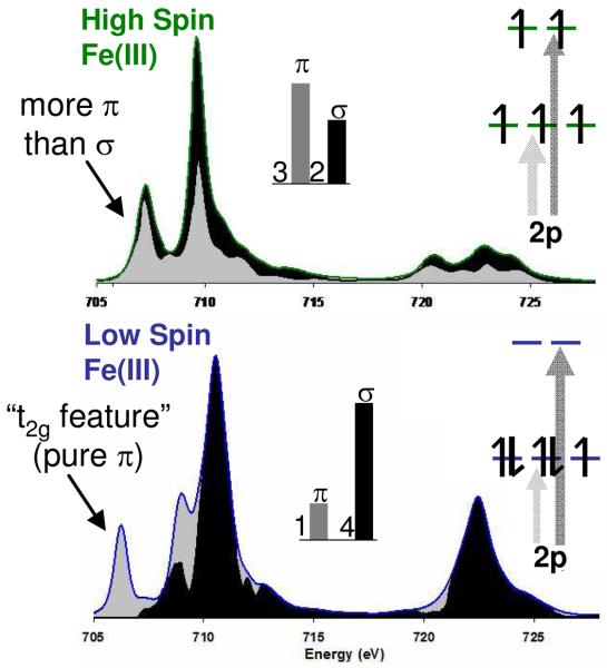
In order to interpret differential orbital covalency from the L-edge spectral shape it is necessary to identify regions of the spectrum that are dominated by transitions to the different symmetry sets of orbitals, t2g(π) and eg(σ) in Oh. The spectral shape at an L-edge is strikingly different for the different spin states. Representative L-edge spectra of low spin and high spin Fe(III) are given in Figure 8, along with the σ and π contributions to the spectra, i.e. density of states. In the low spin case the t2g/eg orbital splitting is large relative to electron repulsion, producing a low energy feature which is pure π, labeled the “t2g feature”.
Figure 8.
Comparison of the Fe L-edges of a typical high spin Fe(III) complex (top) and a low spin Fe(III) complex (bottom). Orbital population inserts indicate the origin of σ and π intensity (arrows) which then distribute over the states due to e-e repulsion as indicated by black (σ) and grey (π), DOS.
While there is only one hole in the t2g orbitals in the low spin configuration, (t2g)5(eg)0, this feature is well separated from the four transitions to the e holes and the relative π and σ contributions to bonding can be quantified. Note from Figure 8, bottom, that for the low spin complex there is some π character mixed into the lower energy side of the σ states through CI but that this is included in the VBCI fits.
For Fe(III) high spin complexes, electron repulsion is large relative to the ligand field splitting and there is no pure π or σ feature. However, σ and π states do distribute differently over the shape of the L-edge spectrum as indicated by the grey (π) and black (σ) states in Figure 8, top. In high spin d5 the t2g3eg2 configuration gives a 3:2 intensity ratio for the π:σ contributions to the spectrum in the absence of differences in covalency. Thus, both the contributions from the π and σ orbitals impact the spectral shape. The low energy spectral feature has more π(t2g) character than the second, and the spectral shape can still be simulated to extract the DOC.
2. Origin of the Differences in Covalency
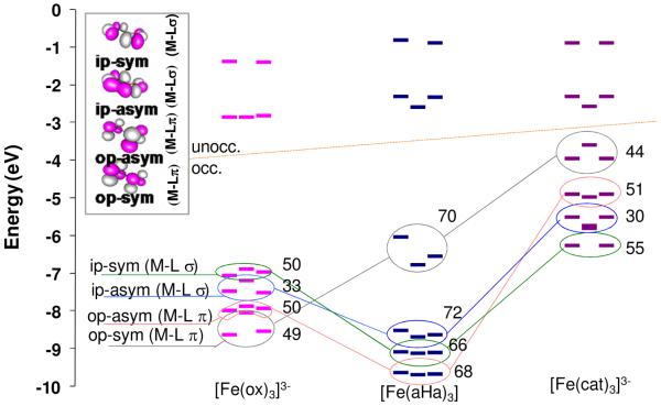
The differences in oxalate, catecholate and hydroxamate ligand covalent bonding to high spin Fe(III) described above reflect differences in the natures of the bonding orbitals of the ligands. Before interaction with the metal there are four sets of mostly O localized valence orbitals: Sym and anti-sym combinations of out-of-plane (op) and in-plane (ip) orbitals, perpendicular to the O-C bonds. The out-of-plane form π bonds to the Fe and the in-plane form σ bonds. Each splits into a set of three MOs as there are three bidentate ligands in the Fe(III) complexes. Contours of these orbitals for oxalate are shown in Figure 9, upper left. Figure 9 shows the β-spin energy levels for both occupied ligand bonding orbitals and the unoccupied metal d orbitals; the numbers offset to the right of the ligand bonding orbitals are the O coefficients as calculated for a free ligand with an ionic counter-ion (Na+ or Mg2+). Each symmetry set of orbitals is circled and correlated with different colored lines to equivalent orbitals on each ligand to facilitate comparison. An equivalent plot of the free ligand orbitals before bonding is given in Figure S4 which shows similar trends.
Figure 9.
Comparison of the β spin energy levels in high spin Fe(III) tris oxalate, [Fe(ox)3]3−, Fe(III) tris hydroxamate [Fe(aha)3] and Fe(III) tris catecholate [Fe(cat)3]3−. Numbers indicate the O character in the corresponding orbital of the free ligand (shown in the contours, in inset). Lines join the orbitals in the different manifolds with similar intra ligand bonding.
In Figure 9 the unoccupied metal orbitals above the line and occupied ligand donor manifolds are below the line. In the unoccupied d orbitals in Figure 9 the D3 distortion from Oh symmetry splits the π set particularly in the hydroxamate and catecholate complexes. However, the effect of this D3 distortion on L-edge spectral shape has been evaluated and is given in Figure S5 and is minor. (vide supra)
Figure 9 importantly also reveals key differences in the relative energies of the ligand donor orbitals. The entire catecholate bonding manifold (purple, far right) has shifted to higher energy relative to that of oxalate (pink, far left). In addition, the orbital energies have re-ordered with the op-sym (π) orbital (circled in grey, Figure 9) shifting from deepest energy in the oxalate manifold to the highest energy orbital (HOMO) of the catecholate manifold.
When two orbitals interact the energy gained is approximated by (HM-L)2/Δ where Δ is the energy difference between the metal and the ligand orbitals before bonding and HM-L is the resonance integral associated with ligand-metal overlap. As the O coefficients, (Figure 9) and Fe-O bond distances (Scheme 1) are similar for oxalate and catecholate the resonance integrals should be similar for both the σ and π bonding interactions. Thus the origin of the increased σ and π donation in [Fe(cat)3]3− relative to [Fe(ox)3]3− is the decreased orbital energy difference Δ. This is reflected in the absorption spectra by the presence of the low energy intense π charge transfer band in [Fe(cat)3]3−,10 which is absent in [Fe(ox)3]3−.74 This energy difference reflects the bonding differences of the two ligand fragments; the O-C distance directly adjoining the Fe-O bond is substantially shorter in oxalate, 1.28 Å, compared to 1.34 Å, catecholate, Scheme 1. The shorter bond length in ox indicates the system is more π delocalized over the O2C fragment and therefore stabilized in energy, decreasing its π interaction with the FeIII.75,76
For the hydroxamate, it is more difficult to estimate the relative contributions because the O character in the valence orbitals is quite different. While the covalent contribution to bonding is higher than for the ox (Table 4), the strength of the Fe(III)-hydroxamate bond is substantially weaker due to the lower ionic contribution to bonding (Table 5). In solvent this weaker bond is more than compensated by the reduced solvation of the hydroxamate relative to the dianionic catecholate and oxalate.
3. Stability Constants
The spectral shapes of the Fe L-edges in Figure 3 have been analysed and used to quantify the differential orbital covalencies of the catecholate and hydroxamate complexes relative to oxalate. The results in Table 4 quantify the electronic structure contributions to the high stability constants in terms of σ and π covalent contributions to bonding from experimental covalencies. As the coefficients of O character in ox and cat orbitals are similar (Figure 9) we can estimate the relative energy contributions to bonding from the experimental σ and π covalencies. From the above discussion the bonding energy is α (HM-L)2 /Δ. while the coefficient squared of ligand character in the metal d orbital (i.e. covalency) α (HM-L/Δ)2. Therefore the bonding energy is proportional to the covalency scaled by the energy differences of the interacting orbitals (energy α (coefficient)2*Δ). Based on a combination of the VBCI fits (Table 4) and DFT calculations (Figure 9), we can estimate Δ and the coefficients of mixing for ox and cat complexes.77 This analysis indicates that ~20% of the energy difference between [Fe(ox)3]3− and [Fe(cat)3]3− is due to the increase in π bonding; the larger contribution is in fact due to the increase in σ bonding, even though the σ and π orbital covalencies increase by similar amounts (20% Δπ, 17% Δσ, Table 4). The larger contribution to the increase in bond strength from a similar increase in σ relative to π covalency reflects the larger energy separation of the ligand σ donor orbitals from the metal levels, Figure 9. Thus a more limited contribution to the covalency from deeper energy orbitals can still make a significant energy contribution to bond strength.
Supplementary Material
Acknowledgements
RKH thanks Dr Erik C. Wasinger and Dr Ritimukta Sarangi for their assistance with the multiplet program and beam-line operations at SSRL. We would like to acknowledge early contributions to this work by Dr Tami Westre, Ms Ekaterina Y. Shishova, and Drs. Emily Dertz and Jide Xu. This work was supported by grants from the NIH GM-40392 and NSF CHE-0446304 to E.I.S., NIH RR-01209 to K.O.H, and NIH AI11744 to K.N.R. The synchrotron data described herein was collected at SSRL, which is funded by the DOE Office of Basic Energy Sciences. The SSRL Structural Molecular Biology Program is supported by the NIH National Center for Research Resources, Biomedical Technology Program and by the DOE Office of Biological and Environmental Research. The NCI national facility Australia and the Monash Sun Grid are acknowledged for access to computer time.
Footnotes
Supporting Information Available
Complete version of references 36 and 37. Table S1 the energies and intensities of the fits to the Fe K pre-edges shown in Figure 2; Figure S1 The effect of d-d spin orbit on the spectrum of high spin Fe(III); Figure S2 the set of simulations used to generate Figure 6; a more detailed explanation of the derivation of Figure 6; Figure S3 is an expansion of the energy region to show both L3 and L2 shown in Figure 7; Figure S4 shows the four highest occupied orbitals of the free ligands prior to bonding. Table S2 is the key geometric parameters from the geometry optimization; Table S3 A comparison of calculated and experimental thermodynamics values for tris Fe, Ga and Al complexes of oxalate, hydroxamate and catecholate. Figure S5 octahedral and lower symmetry multiplet simulations. This material is available free of charge via the Internet at http://pubs.acs.org.
References
- 1.Neilands JB, Konopka K, Schwyn B, Coy M, Francis RT, Paw BH, Bagg A. Iron Transport in Microbes, Plants and Animals. 1987 [Google Scholar]
- 2.Neilands JB. J. Biol. Chem. 1995;270:26723–26726. doi: 10.1074/jbc.270.45.26723. [DOI] [PubMed] [Google Scholar]
- 3.Codd R. Coord. Chem. Revs. 2008;252:1387–1408. [Google Scholar]
- 4.Raymond KN, Dertz EA, Sanggoo S. Proc. Nat. Acad. Sci. 2003;100:3584–3588. doi: 10.1073/pnas.0630018100. [DOI] [PMC free article] [PubMed] [Google Scholar]
- 5.Meyer JM, Hohnadel D, Hall F. J. Gen. Microb. 1989;135:1479–1487. doi: 10.1099/00221287-135-6-1479. [DOI] [PubMed] [Google Scholar]
- 6.Spasojevic I, Armstrong SK, Brickman TJ, Crumbliss AL. Inorg. Chem. 1999;38 doi: 10.1021/ic980635n. [DOI] [PubMed] [Google Scholar]
- 7.Carrano CJ, Dreschsel H, Kaiser D, Jung G, Berhold M, Wilnkelmann G, Rochel N, Albercht-Gray AM. Inorg. Chem. 1996;35:6429–6436. doi: 10.1021/ic960526d. [DOI] [PubMed] [Google Scholar]
- 8.Dari-Abu K, B. S. J, Riley PE, Raymond KN. Inorg. Chem. 1983;22:3085–3089. [Google Scholar]
- 9.Gerrett TM, Miller PW, Raymond KN. Inorg. Chem. 1989;28:128–133. [Google Scholar]
- 10.Karpishin RB, Gebhard MS, Solomon EI, Raymond KN. J. Am. Chem. Soc. 1991;113:2977–2984. [Google Scholar]
- 11.Andreas NC. N. Engl. J. Med. 1999;342:1293–1294. [Google Scholar]
- 12.Oliver NF, Brittenham GM. Blood. 1997;89:729–761. [Google Scholar]
- 13.Esington EH, Nishita H. Plant and Soil. 2005;24:1–23. [Google Scholar]
- 14.Chao JC, Hong A, Okey RW, Peters RW. Proc. Conf. Hazardous Wast Research. 1998 [Google Scholar]
- 15.Deneux M, Meiller R, Benoit RL. Can. J. Chem. 1968;46:1383–1383. [Google Scholar]
- 16.Wasinger EC, deGroot FMF, Hedman B, Hodgson KO, Solomon EI. J. Am. Chem. Soc. 2003;125:12894–12906. doi: 10.1021/ja034634s. [DOI] [PubMed] [Google Scholar]
- 17.George SJ, Lowery MD, Solomon EI, Cramer SP. J. Am. Chem. Soc. 1993;115:2968–2969. [Google Scholar]
- 18.Kotani A, Okada K. Tech. Rep. ISSP, Ser. A. 1992;Ser. A:2562. [Google Scholar]
- 19.van der Laan G, Zaanen J, Sawatzky GA, Karnatak R, Esteva JM. Phys. Rev. B. 1986;33:4253–4263. doi: 10.1103/physrevb.33.4253. [DOI] [PubMed] [Google Scholar]
- 20.Sugano S, Tanabe Y. Multiplets of transition-metal ions in crystals. Academic Press; New York: 1970. [Google Scholar]
- 21.Note that throughout the ms data was taken on the tris propyl hydroxamate complexe of Fe, [Fe(pha)3], and that stability constant data and calculations are taken on the tris acetohydroxamate complex of Fe, [Fe(aha)3]. The small difference between the two is illustrated in Scheme 1.
- 22.Abu-Dari K, Raymond KN. J. Am. Chem. Soc. 1977;99:2003–2005. doi: 10.1021/ja00448a067. [DOI] [PubMed] [Google Scholar]
- 23.Raymond KN, Isied SS, Brown LD, Fronczek FR, Nibert JH. J. Am. Chem. Soc. 1976;98:1767–1777. doi: 10.1021/ja00423a022. [DOI] [PubMed] [Google Scholar]
- 24.Westre TE, Kennepohl P, DeWitt JG, Hedman B, Hodgson KO, Solomon EI. J. Am. Chem. Soc. 1997;119:6297–6314. [Google Scholar]
- 25.DeBeer George S, Metz M, Szilagyi RK, Wang H, Cramer SP, Lu Y, Tolman WB, Hedman B, Hodgson KO, Solomon EI. J. Am. Chem. Soc. 2001;123:5757–5767. doi: 10.1021/ja004109i. [DOI] [PubMed] [Google Scholar]
- 26.Yeh JJ, Lindau I. At. Data Nucl. Data Tables. 1985;32:1–155. [Google Scholar]
- 27.Scott RA, Hahn JE, Doniach S, Freeman HC, Hodgson KO. J. Am. Chem. Soc. 1982;104:5364–5369. [Google Scholar]
- 28.Thole BT, van der Laan G, Fuggle JC, Sawatzky GA, Karanatak RC, Esteva J-M. Phys. Rev. B. 1985;32:5107–5118. doi: 10.1103/physrevb.32.5107. [DOI] [PubMed] [Google Scholar]
- 29.Cowan RD. The Theory of Atomic Structure and Spectra. University of California Press; Berkeley: 1981. [Google Scholar]
- 30.Butler PH. Point Group Symmetry, Applications, Methods and Tables. New York: 1991. [Google Scholar]
- 31.Failes TW, Hambley TW. Aust. J. Chem. 2000;53:879–881. [Google Scholar]
- 32.Wartchow R. Z. Kristallogr. 1997;212:57–58. [Google Scholar]
- 33.Fourquet JL, Plet F, Y. C, De Pape R. J. Solid. State. Chem. 1987;69:76–80. [Google Scholar]
- 34.Mulliken RS. J.Chem. Phys. 1955;23:1833–1840. [Google Scholar]
- 35.Scientific Computing and Modeling (SCM) ADF User's Guide. Amsterdam: 2003. [Google Scholar]
- 36.Baerends EJ, et al., editors. ADF2003.01, SCM, Theoretical Chemistry. Vrije Universiteit; Amsterdam, The Netherlands: http://www.scm.com. [Google Scholar]
- 37.Frisch MJ, et al., editors. Gaussian 03 Revision 01. 2003 [Google Scholar]
- 38.Becke AD. Phys. Rev. A. 1988;38:3098–3100. doi: 10.1103/physreva.38.3098. [DOI] [PubMed] [Google Scholar]
- 39.Perdew JP. Phys. Rev. B. 1986;33:8822–8824. doi: 10.1103/physrevb.33.8822. [DOI] [PubMed] [Google Scholar]
- 40.Baerends EJ, Ellis DE, Ros P. Theor. Chim. Acta. 1972;27:339–354. [Google Scholar]
- 41.Te Velde G, Baerends EJ, Fonseca GC, Van Gisbergen SJA, Snijders JG, Ziegler T. J. Comput. Chem. 2001;22:931–967. [Google Scholar]
- 42.Ryde U, Olsson MHM, Pierloot K. Theoretical and Computational Chemistry. 2001;9:1–55. [Google Scholar]
- 43.Siegbahn PEM, Blomberg MRA. Chem. Rev. 2000;100:421–437. doi: 10.1021/cr980390w. [DOI] [PubMed] [Google Scholar]
- 44. http://www.csc.fi/gopenmol/distribute/index.phtml.
- 45.Klamt A. J. Chem. Phys. 1995;99:2224. [Google Scholar]
- 46.Klamt A, Jones V. J. Chem. Phys. 1996;105:9972. [Google Scholar]
- 47.Klamt A, Schuurmann G. J. Chem.Soc: Perkin Trans 2. 1993;799 [Google Scholar]
- 48.Mennucci B, Cances E, Tomasi J. J. Phys. Chem. 1997;B101:10506–10507. [Google Scholar]
- 49.Cammi R, Mennucci B, Tomasi J. J. Phys. Chem. 1999;A103:9100–9102. [Google Scholar]
- 50.Cammi R, Mennucci B, Tomasi J. J. Phys. Chem. A. 2000;104:5631–5632. [Google Scholar]
- 51.Lever ABP, I. GS. Struct. and Bond. 2004;107:77–114. [Google Scholar]
- 52.Gorelsky SI, Basumallick L, Vura-Weis J, Sarangi R, Hodgson KO, Hedman B, Fujisawa K, Solomon EI. Inorg. Chem. 2005;44:4947–4960. doi: 10.1021/ic050371m. [DOI] [PMC free article] [PubMed] [Google Scholar]
- 53.Gorelsky SI. AOMix program, rev. 5.93. 2004 http://www.sg-chem.net/
- 54.Gorelsky SI, Lever ABP. J. Organomet. Chem. 2001;635:187–196. [Google Scholar]
- 55.Tenderholt AL, Hodgson KO, Hedman B, Solomon EI. QMForge A program for the analysis of MO coefficients. 2005 This software is avilable free of charge at http://pymolyze.sourceforge.net. [Google Scholar]
- 56.Atkins PW. Physical Chemistry. 3rd Edition Oxford University Press; 1986. [Google Scholar]
- 57.Thole BT, van der Laan G. Phys. Rev. 38B. 1988:3158–3170. doi: 10.1103/physrevb.38.3158. [DOI] [PubMed] [Google Scholar]
- 58.Figgis BN, Hitchman MA. Ligand Field Theory and Its Applications. WILEY-VCH; 2000. [Google Scholar]
- 59.Wang H, Peng G, Miller LM, Scheuring EM, George SJ, Chance MR, Cramer SP. J. Am. Chem. Soc. 1997;119:4921–4928. [Google Scholar]
- 60.Hocking RK, Wasinger EC, deGroot FMF, Hodgson KO, Hedman B, Solomon EI. J. Am. Chem. Soc. 2006;128:10442–10451. doi: 10.1021/ja061802i. [DOI] [PubMed] [Google Scholar]
- 61.Sarangi R, Nermeen A, Fujisawa K, Tolman WB, Hedmand B, Hodgson KO, Solomon EI. J. Am. Chem. Soc. 2006;128:8286–8296. doi: 10.1021/ja0615223. [DOI] [PMC free article] [PubMed] [Google Scholar]
- 62.Note that for high spin Fe(III) d-d repulsion does not cause any additional splitting.
- 63.Population analysis was done using C2
- 64.Bray MR, Deeth RJ, Paget VJ, Sheen PD. Int. J. Quantum Chem. 1996;61:85–91. [Google Scholar]
- 65.Hocking RK, Deeth RJ, Hambley TW. Inorg. Chem. 2007;46:8238–8244. doi: 10.1021/ic701166p. [DOI] [PubMed] [Google Scholar]
- 66.Motekaitis RJ, Martell AE. Inorg. Chim. Acta. 1991;183:71–80. [Google Scholar]
- 67.Avdeef A, Sofen SR, Bregante TL, Raymond KN. J. Am. Chem. Soc. 1978;100:5362–5370. [Google Scholar]
- 68.Smith RM, Martell AE. Critical Stability Constants. Vol. 3. Plenum Press; New York: 1974. [Google Scholar]
- 69.Stary J. Anal. Chim. Acta. 1962;28:132–149. [Google Scholar]
- 70.Fein J, Hestrin JE. Geochim. Cosmo. Acta. 1994;58:4817–2829. [Google Scholar]
- 71.Burgess J, Patel MS. J. Coord. Chem. 1993;29:65–71. [Google Scholar]
- 72.Farkas E, Kozma E, Kiss T, Toth I, Kurzak B. J. Chem. Soc. Dalton. Trans. 1995:477–480. [Google Scholar]
- 73.Evers A, Hancock RD, Martell AE, Motekaitis RJ. Inorg. Chem. 1989;28:2189–2195. [Google Scholar]
- 74.Holt S, Dingle R. Acta. Chem. Scand. 1968;22:1091–1095. [Google Scholar]
- 75.Pau MYM, Davis MI, Orville AM, Lipscomb JD, Solomon EI. J. Am. Chem. Soc. 2007;129:1944–1958. doi: 10.1021/ja065671x. [DOI] [PMC free article] [PubMed] [Google Scholar]
- 76.Pau MYM, Lipscomb JD, Solomon EI. PNAS. 2007;104:18355–18362. doi: 10.1073/pnas.0704191104. [DOI] [PMC free article] [PubMed] [Google Scholar]
- 77.For [Fe(cat)3]3−: dπ Δ=2.0eV and 26% ligand character therefore E α (0.26)*2.0 =0.52; dσ Δ=5.5eV and 48% ligand therefore E α (0.48)*5.5=2.64 eV; For [Fe(ox)3]3−: dπ Δ=6.0eV and 6% ligand character therefore E α (0.06)*6 =0.36 eV; dσ Δ=6.0eV, 31% ligand, E α (0.31)*6 =1.86 eV. The total energy difference [Fe(cat)3]3− − [Fe(ox)3]3− = 0.94eV ; Total energy difference dπ 0.16eV or 17% of total energy.
Associated Data
This section collects any data citations, data availability statements, or supplementary materials included in this article.


