

Abstract
Mixed echo train acquisition displacement encoding with stimulated echoes (meta-DENSE) is a phase-based displacement mapping technique suitable for imaging myocardial function. This method has been optimized for use with patients who have a history of myocardial infarction. The total scan time is 12–14 heartbeats for an in-plane resolution of 2.8 × 2.8 mm2. Myocardial strain is mapped at this resolution with an accuracy of 2% strain in vivo. Compared to standard stimulated echo (STE) methods, both data acquisition speed and resolution are improved with inversion-recovery FID suppression and the meta-DENSE readout scheme. Data processing requires minimal user intervention and provides a rapid quantitative feedback on the MRI scanner for evaluating cardiac function.
Keywords: cardiac, function, DENSE, meta-DENSE, STEAM, HARP, tagging, phase contrast, stimulated echoes, fast-DENSE, dual-echo DENSE, heart, PC, MRI, strain
Cardiac functional imaging based on displacement encoding with stimulated echoes (DENSE) has been proposed as a high-resolution method for evaluating cardiac contractility (1–5). This was first combined with a segmented echo-planar imaging readout (fast-DENSE), and its application has been demonstrated with normal volunteers (6). However, two issues arose with respect to utilizing this methodology for routine patient cardiac functional evaluation. First, the signal-to-noise ratio (SNR) of the images acquired was insufficient for encoding the entire systolic interval. Specifically, only the last 100–150 ms of systole were captured for functional evaluation. Second, the breath-holds required for such exams were on the order of 26 heartbeats. This certainly posed a problem for evaluating function in patients with myocardial infarction. The solution to both issues is presented in this work. It involves a new way of sampling the stimulated echo (STE) signal and improved resolution by suppressing the FID signal. This method, mixed echo train acquisition DENSE (meta-DENSE), is applied successfully in both normal volunteers and patients to quantitatively evaluate cardiac function at high resolution in situ.
In our previous work with fast-DENSE, the duration of the encoding interval and data acquisition speed were both constrained by the SNR, as already mentioned (Fig. 1). Since DENSE is based on STEs, there is an inherent 50% signal loss. In addition, myocardial strain alters the shape of the voxels during the encoding period. As a result, intravoxel dephasing can further lower the SNR, especially where strain is high along the longest dimension of the voxel, i.e., along the slice axis (6,7). Intravoxel dephasing signal loss is accentuated if strong TE gradient pulses are applied along the slice axis (Fig. 1). Such pulses are routinely used in stimulated echo acquisition mode (STEAM) experiments to eliminate unwanted signal contributions that can cause artifacts. The previous implementation (fast-DENSE) used a low RF flip angle segmented-EPI readout. The position-encoded magnetization was recalled in small portions onto the XY-plane and then discarded. Despite its ability to acquire data fast, the EPI-based readout is inefficient for acquiring DENSE data. Unlike other EPI applications, with DENSE the available magnetization that contains useful phase-encoded displacement information is limited. A fast readout scheme that recycles the available magnetization is more suitable for sampling the STE in DENSE experiments. One approach to this goal has been to utilize a fast-spin-echo (FSE) readout (8,9). That method yielded 3D static displacement strain images. However, there were significant artifacts with the normal FSE readout. The source of these artifacts can be traced to the mixing of the original STEAM signal with additional STEs that are created by the FSE pulse train (10).
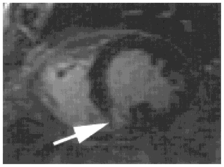
FIG. 1.

Fast-DENSE image acquired with a segmented EPI readout. Note the signal loss due to intravoxel dephasing in the myocardium (arrow). This magnitude image was acquired with an encoding interval of 100 ms covering the end portion of systole.
Alternative FSE readouts applied to diffusion weighting can be utilized to sample the STEAM signal. In one such approach, diffusion weighting was accomplished via the Stejskal Tanner sequence (11) and read out was performed in a single-shot via phase-insensitive rapid acquisition with relaxation enhancement (RARE) preparation (12). This preparation, via a dephasing gradient, divides the signal evenly between a Meiboom Gill (MG) (13) and an orthogonal component. The latter is then nutated onto the z-axis, where it remains during image acquisition, allowing the MG component to be imaged free of artifacts. It is important to note that if a signal has already lost its non-MG component, such a phase-insensitive RARE preparation is no longer required. One such signal is that generated by the STEAM preparation in DENSE, as will be shown. Therefore, the STEAM signal can be sampled by a train of 180° pulses with no artifacts. Another approach to sampling the STEAM signal is split acquisition of fast spin-echo signals for diffusion imaging (14), which has also utilized an FSE readout. However, SPLICE reduces artifacts by reconstructing two separate magnitude images from two echo trains (14) created by a readout gradient imbalance rather than exploiting the inherent MG properties of the STEAM signal. Indeed, the two echo trains of SPLICE can be forced to coincide with the STE and the stimulated anti-echo (STAE) (15) of STEAM and result in artifact-free images, as will be described later.
In this work, the underlying cause of artifacts generated in STEAM displacement imaging with a conventional FSE readout is explained. The use of the STAE along with the conventional notion of the STE will facilitate the description process. It will be shown that the DENSE preparation is inherently compatible with a specialized readout train of 180° refocusing pulses, and as such artifact-free phase images can be obtained. The STEAM signal, which is comprised of two components, is RF-refocused so that not only is phase-contrast consistency maintained but also any additional STEs, created by imperfect 180°s during the readout, combine coherently with its two components.
Additionally, an inversion-recovery nulling method will be used to eliminate unencoded water and fat signal contributions, which can cause artifacts when low encoding strengths are used in conjunction with high resolution. Finally, data acquired with this new method from normal volunteers and a patient in 14 heartbeats will be shown.
THEORY
The typical STEAM sequence is shown in Fig. 2. The magnetization is initially tipped onto the transverse plane by a 90° RF pulse (Fig. 2, point A) where it is position-encoded by means of a gradient pulse (Fig. 2, point B). The phase is modulated not only by position but also by off-resonance and main field inhomogeneity. For spins located at position r1, the total phase in the rotating frame of reference prior to the second 90° pulse (Fig. 2, point C), which stores the magnetization along the longitudinal axis, is
FIG. 2.

Schematic representation of the STEAM pulse sequence. Depending on the polarity of the gradient pulse (k2) during TE2, an STE or an STAE will be created, as explained in the Theory section.
| [1] |
where γ is the gyromagnetic ratio, TE/2 = TE1 = TE2, ωOFF is the off-resonance offset, γΔBo is the main field inhomogeneity and k1 is the 0th-order moment imposed by the position-encoding gradient fields during TE1 along the r direction (where r is x, y, or z). Off-resonance and main field inhomogeneity phase accumulations have similar behavior due to their dependence on TE. As such, both TE-dependent terms can be treated similarly and summarized by
| [2] |
Therefore, phase accumulation during the first half of TE is attributed to the TE-dependent terms and gradient pulses. As a result, from Eqs. [1] and [2], the transverse magnetization is described by
| [3] |
Assuming that the second 90° RF pulse (Fig. 2, point C) is along the direction that tips the real component of the transverse magnetization along the z-axis, this component of the transverse magnetization is preserved along the −z during the displacement-encoding period TM. This is
| [4] |
The imaginary part remains on the transverse plane, where it decays rapidly due to and gradient crushing (not shown in the figure). Equation [4] describes the STEAM signal, which consists of two equally useful parts with half the amplitude of the initial magnetization: both the original magnetization and its complex conjugate are stored along −z. Spin coherence is preserved along the longitudinal axis for a long time period (TM) limited only by T1. When the third 90° RF pulse (Fig. 2, point D) restores the magnetization vector onto the transverse plane the spins are located at a new position, r2. Due to the phase imparted by the RF pulses, the transverse magnetization immediately following the third 90° nutation (Fig. 2, point D) is
| [5] |
Then, during TE2, additional phase will accumulate due to off-resonance and main field inhomogeneity as well as a result of the application of the gradient moment k2 (Fig. 2, point E). This phase is described by
| [6] |
Therefore, the transverse magnetization at the center of the acquisition window (Fig. 2, time point F) is
| [7] |
In conventional STEAM experiments, k1 = k2 by design. Therefore, in the presence of motion (r2 ≠ r1), the transverse magnetization is
| [8] |
where δ = (r2 − r1) is the displacement incurred over the TM period. The first part of the transverse magnetization described by Eq. [8] corresponds to the STE. Since TE/2 = TE1 = TE2, phase accumulation due to the TE-dependent terms is negligible, i.e., (S1 − S2) = 0. Thus, the STE resembles a spin-echo and its phase is mainly modulated by the displacement term; however, compared to a spin-echo, additional signal loss occurs due to T1 relaxation during TM (1). The STE is the DENSE signal described in prior displacement encoding schemes (3,6). The phase of the second part of the signal described by Eq. [8] is mainly modulated by 2γk1r2. In imaging experiments, k1 has to be strong enough to shift this unwanted component outside the part of k-space that is sampled to create a STEAM image. Otherwise, banding artifacts appear in the image. When this unwanted component is filtered out prior to the Fourier transform (FT), the remaining DENSE signal, which is sampled to form an image, has its phase modulated only by displacement. With such appropriate filtering the signal Ψ acquired is
| [9] |
It is interesting to note that in the presence of motion, phase accumulated due to field inhomogeneity will be different for r1 and r2. Therefore, the S1 and S2 phase shifts are not equal. In prior DENSE experiments with a reference scan (6), this additional phase error was removed.
The second term of the preserved magnetization (Eq. [7]) can be refocused by applying gradient pulses of opposite polarities (k1 = −k2) during TE1 and TE2 (Fig. 2, point B and point E dotted line). In this manner, an STAE is created (15). In this case, from Eq. [7], the transverse magnetization is
| [10] |
The second term of this magnetization is modulated by displacement (δ) but also by off-resonance and main field inhomogeneity (S1 + S2); thus, it resembles a gradient echo. This was the reason for not using the STAE in prior DENSE experiments. Moreover, compared to a gradient echo, additional signal loss occurs due to T1 relaxation during TM. With proper filtering, the sampled signal Ψ is
| [11] |
The STAE still reflects the displacement δ that occurred between the two gradient pulses, which are applied during TE1 and TE2. Note that the displacement-induced phase is of the opposite sign when compared to the STE (Eq. [9]).
Compared to small flip angle readout schemes, a fast-spin-echo (FSE) readout (Fig. 3) is desirable because it yields images with higher SNR. However, the FSE readout causes significant artifacts when used to rapidly sample the displacement-encoded STEAM signal. Only under ideal conditions can these artifacts be eliminated. This is demonstrated by assuming that the signal generated originally with gradients of the same polarity (k1 = k2) (Fig. 3, time point A), as described by Eq. [8], and that the STE is sampled. It is also assumed that no motion occurs during the readout period. Just prior to the first 180° refocusing pulse (Fig. 3, time point B), additional phase will have accumulated due to off-resonance and main field inhomogeneity during TE3 (Fig. 3, time interval AB). At that time (Fig. 3, time point B), the magnetization is described by
FIG. 3.

Schematic representation of a fast spin echo (FSE) readout to rapidly sample the signal generated by a STEAM experiment. This method generates artifacts with DENSE, as described in the text.
| [12] |
Following the first 180° pulse and after TE4 time has elapsed (Fig. 3, time point C), the magnetization that is sampled is
| [13] |
Similarly, it can be derived that at the center of the third acquisition window (Fig. 3, time point D), Mxy returns to its original form described by Eq. [8]. If k-space is filled with lines sampled following every refocusing pulse, half of the lines will correspond to signal described by Eq. [8] while the other half corresponds to Eq. [13]. Even though the STE is sampled in both cases, it changes sign after every refocusing pulse. If the refocusing pulses are performing ideally (i.e., spins are nutated by 180° throughout the imaged volume) and their phase relative to the third 90° pulse is zero, then artifact-free data can be obtained by conjugating every other line of the k-space matrix. However, it has been shown that such assumptions are not possible with FSE (16) since an imperfect refocusing train creates additional stimulated echoes. Thus, the transverse magnetization becomes increasingly a mixture of the desired signal and its complex conjugate (with proportionality factors α and β, respectively), as described by the following equation:
| [14] |
Therefore, after proper filtering, the sampled signal Ψ is now a combination of the desired STE and the undesired STAE as seen below
| [15] |
Thus, depending on the k-space sampling scheme, the interference between these two components can give rise to a variety of artifacts.
A specialized readout, compatible with the position-encoded STEAM magnetization, can be used to produce artifact-free images by means of refocusing pulses. This particular implementation, meta-DENSE, is depicted in Fig. 4. The main purpose of this method is to ensure that the motion-induced phase is consistent among all lines of k-space. Moreover, any contribution to the acquired signal from local stimulated echoes created by the readout pulse train will add to the existing signal in a coherent manner. As discussed below, this acquisition method ensures that phase contributions from off-resonance and main field inhomogeneity are also uniform in k-space.
FIG. 4.

Schematic representation of our proposed pulse sequence, meta-DENSE, to rapidly sample both parts of the signal generated by a STEAM experiment via 180° refocusing pulses.
To minimize the time interval between successive refocusing pulses (i.e., the echo spacing), the signal arising from the third 90° (Fig. 4, point A) is not sampled immediately but is allowed to experience the first 180° pulse (Fig. 4, point B). With this implementation, the interval bracketed by the first two 90° pulses (t1) is kept as short as possible. Let S1 be the phase accumulated due to off-resonance and main field inhomogeneity during t1 while S2 is the corresponding phase accumulated during TE1. To simplify the description of this method, the first refocusing pulse is considered ideal, and any gradient crushers that bracket each refocusing pulse (not shown in the figure) are combined with S2 as follows:
| [16] |
where kc is the moment of a single gradient crusher pulse. In this case, the extra dephasing imparted by the crusher is considered to be a characteristic of a particular TEi time period. Due to the crusher, it is clear that S1 ≪ S2′. The transverse magnetization right after the third 90° pulse (Fig. 4, time point A) is derived from Eq. [5]:
| [17] |
Just prior to the first 180° pulse (Fig. 4, time point B), phase has accumulated as a result of off-resonance, main field inhomogeneity and gradient crushing. Therefore, from Eq. [17], the magnetization at that point in time is
| [18] |
Following the first refocusing pulse, the negative gradient pulse (Fig. 4, time point C) and the influence of the S2′ term during TE2, the magnetization at the center of the first acquisition window (Fig. 4, time point D) is
| [19] |
The first part of the signal, which can be sampled, contains contamination from S1 and displacement (δ) information. During TE3 additional phase accumulates due to off-resonance, main field inhomogeneity, and the gradient crusher (S2′). Also, the rephasing positive gradient (Fig. 4, time point E) imparts phase γk1r2. Thus, the magnetization at the end of TE3 is described by
| [20] |
The magnetization then experiences the second 180° pulse (Fig. 4, time point F). The spin echo of the signal described by Eq. [20] is mixed with STEs created by the imperfect refocusing pulse (Fig. 4, time point F). Therefore, the transverse magnetization is
| [21] |
If T2 relaxation is ignored then α + β ~ 1. At later echoes within the train, α becomes smaller while β increases (16).
After accumulating additional phase due to the ensuing gradient pulse (Fig. 4, time point G) as well as to off-resonance and main field inhomogeneity (TE4), the transverse magnetization during the second readout period (Fig. 4, time point H) is
| [22] |
Since S2′ contains phase contributions from the crusher pulses that bracket each refocusing pulse, the β term is crushed. Here, the second part of the signal is detectable and contains displacement information along with contamination by S1.
After multiple refocusing pulses, it is tedious to track all stimulated and spin-echo components in this way. However, one can consider the possible forms of these terms in general. Right after a refocusing pulse, terms that contribute to the signal sampled during the readout period must have the form Soe−iS2′ where So does not contain e−iS2′ phase terms. Since each period bracketed by two successive refocusing pulses contains two crusher pulses and therefore adds e±i2S2′ to all terms, a term whose phase has an odd number of S2′s must have originated from the initial 90° excitation. That is, it must have originated from the signal described by Eq. [18]. Thus, these terms, U, conform to the form
| [23] |
where m and n are integers. When (−1)m + 2n = −1 is satisfied the corresponding terms are
| [24] |
The application of the encoding gradient pulse prior to the readout period combined with the S2′ term yields the refocused magnetization
| [25] |
The signal acquired is the second term in Eq. [25] and it is phase consistent. Therefore, it results in artifact-free images. As discussed previously (3), S1 contributions can be removed by a reference scan. The meta-DENSE sampling scheme can be used to collect data for a number of echoes limited only by T2 relaxation.
Another factor that limits the efficiency of the sequence is the FID signal, which arises from T1 relaxation during the TM period (Fig. 2). Naturally, spin-lattice relaxation results in T1 contrast for the STEAM image. However, spins that relax according to T1 during the TM interval will have effectively not experienced the STEAM preparation and as such will form a regular FID signal. As a result, they do not contribute to the final STEAM image but can be the source of artifacts since they have effectively not experienced the first gradient pulse that is applied during the first half of TE (Fig. 2, point B). The major source of phase accumulation onto these spins is the gradient pulse k2, which is applied at time point E (Fig. 2). This phase is
| [26] |
Unless the gradient moment k2 is strong enough to move the FID signal outside the k-space area that is sampled to form the STEAM image, artifacts will appear in the form of stripes. This is the mechanism that is exploited in myocardial tagging experiments. With DENSE experiments, this much-needed gradient moment k2 can cause severe signal loss due to intravoxel dephasing. This is particularly true when long encoding periods are desired. The combination of extensive muscle deformation with strong k1 and k2 gradient moments can render the DENSE dataset useless due to low SNR values. Therefore, suppression of the FID signal is desirable in order to use smaller k1 and k2 gradient moments. The application of strategically placed inversion pulses during the TM period can sufficiently suppress the FID for multiple tissues with different T1 so that k1 and k2 can be lowered to accommodate DENSE experiments that cover the entire systolic interval. For FID suppression, this is particularly useful since a gradient pair along the slice direction is undesirable because it can cause extreme intravoxel dephasing (7).
The pulse sequence that describes the FID suppression method with one inversion pulse during TM is shown in Fig. 5. Longitudinal relaxation during TE1 is not considered here since any spins that relax along the z-axis during this time period will be eventually scrambled after the second 90° pulse. Relaxation during TE2 is not considered either since any signal formed by T1 relaxation during this time interval will not be part of the STEAM image. The TM period is divided into two parts (TM1 and TM2) by the inversion pulse. During TM1, the longitudinal relaxation of the crushed magnetization is described by
FIG. 5.

Schematic representation of the STEAM pulse sequence with FID suppression. The mixing time (TM) is divided in two segments (TM1 and TM2) by an inversion pulse.
| [27] |
The 180° RF pulse inverts this magnetization. Therefore, it becomes
| [28] |
At the end of the TM period, the magnetization is described by
| [29] |
For FID suppression, the intervals TM1 and TM2 should be adjusted so that the longitudinal magnetization is crossing zero at the end of TM2. Moreover, TM1 + TM2 = TM and thus Eq. [29] yields
| [30] |
Typical values for a TM period of 300 ms and T1 of 850 ms are TM1 = 163.1 ms and TM2 = 136.8 ms. It is interesting to note that this type of FID suppression is highly T1 dependent. As such, suppression with a single inversion pulse is not applicable to many different tissues but rather to a single T1 moiety. When DENSE experiments are considered, this poses no problem since the cardiac muscle fits this criterion. Therefore, the FID signal can be successfully suppressed for the muscle while other tissues such as fat will suffer from artifacts, as previously described. Alternatively, a fat-saturation narrow band pulse prior to imaging or multiple inversion pulses strategically placed during the TM period can be used to null FID contributions for adipose tissue.
In meta-DENSE with FID-suppression, it is assumed that the two parts of the signal described by Eq. [19] are separated in k-space adequately by means of the encoding gradient moment, k1. This ensures that overlap of the two signal components does not occur. Such overlap can result in high spatial frequency content contamination during signal sampling and therefore diminished edge definition in the images. Unless such a penalty is acceptable, the two echoes have to be separated in k-space by at least γNxGx/BW, where Nx is the number of points along the x-direction, Gx is the readout gradient amplitude, and BW the sampling bandwidth. This translates to a need to utilize encoding gradient strengths (measured in mm/π) of less than half the pixel size. This can be derived from the following three equations:
| [31] |
| [32] |
| [33] |
However, even when this condition is satisfied, there is still some overlap between the two signal components. This overlap does not involve spatial frequencies that are sampled to form an image at a given resolution. Rather, higher frequencies that are not sampled from one signal component overlap with the sampled frequencies of the other. To minimize this interference, it is necessary to collect images of high enough resolution so that the residual higher frequencies are negligible with respect to the noise floor.
METHODS
Experiments were performed in a 1.5T cardiovascular magnet system (LX 8.25M4, General Electric Medical Systems, Milwaukee, WI) with a standard four-element receive-only phased-array coil. The basic principles of the meta-DENSE method were demonstrated with data acquired from phantoms. The important imaging parameters are summarized in the figure captions where appropriate. Data from the human heart were collected to demonstrate the feasibility of the technique in both normal and diseased states. Position encoding during the first half of TE (Fig. 2, point B) was applied immediately following the prospectively detected R-wave. The projection of the magnetization along the x-axis was stored along the longitudinal axis (−z) as soon as possible to minimize transverse dephasing. As described in the Theory section, the spins were under the influence of field inhomogeneity for the duration of the first 90°–90° interval, i.e., t1 = 1.7 ms. The remaining magnetization was scrambled via gradient pulses at the beginning of the displacement-encoding period (TM). The entire position-encoded magnetization was recalled onto the transverse plane for imaging at the beginning of end-systole. Thus, the entire systolic interval was covered. Furthermore, imaging was performed during a period in which little myocardial motion occurs and therefore image quality is best. The correct timing was determined on a case-by-case basis via a CINE long-axis localizer. As such, the displacement-encoding period varied from 250 to 350 ms. For imaging the displacement-encoded magnetization, the meta-DENSE method described in the Theory section was utilized with an echo train length of 24. The total readout window duration was 96.5 ms. With a data matrix of 128 × 96, the required three images (X-encoded, Y-encoded, and the reference) per slice were acquired in 12 heartbeats within a single breath-hold. An additional two heartbeats were used to set the steady state before commencing to image. The k-space matrix was sampled sequentially from top to bottom. Typical in-plane resolution was 2.8 × 2.8 mm2 with a slice thickness of 7–8 mm. The displacement encoding strength was 2.0 mm/π resulting in gradient moments of 588 μs*Gauss/cm for the x and y directions. To improve dynamic range and reduce intravoxel dephasing, these moments were equally divided between the encoded and the reference images as previously described (6). No gradients were used along the z-axis to crush the FID signal. Instead, a Silver-Hoult adiabatic inversion pulse was introduced during the TM period to null the T1-relaxed undesired FID signal contributions. This RF pulse was placed at the appropriate time point calculated by Eq. [30] with the assumption of myocardial T1 of 850 ms. The signal-to-noise ratio (SNR) in strain measurements in vivo was determined with similar imaging parameters following methods previously described (6). In summary, the three images required for DENSE displacement estimation were all acquired with the same encoding gradient moments and were processed in the same manner as regular DENSE datasets. Preliminary meta-DENSE data were acquired from five normal volunteers and a patient with chronic myocardial infarction. To avoid unnecessary prolonged scans with the patient, only data from the normal volunteers were collected to determine the SNR of strain measurements.
Raw k-space data processing was done with custom-written programs in IDL (Research Systems Inc., Boulder, CO). Data for a particular slice were processed on the MR scanner for that slice within 20 s following data acquisition. The user placed a rectangular window over the LV chamber. Thereafter, data processing was automatic. Strain data were displayed on the scanner with stick-plots as described previously (6). This aided subsequent prescription of slices and/or encoding intervals.
RESULTS
Data to demonstrate the various components of the signal sampled with meta-DENSE were collected from phantoms. Figure 6 shows the three components of the STEAM signal that can be sampled by the meta-DENSE readout. In this case the k-space window that is sampled is large compared to the encoding gradient strength along the x-axis (4.0 mm/π). Note that the corresponding image (Fig. 7) suffers from banding artifacts due to the interference of these three signal components. Figure 8 shows a dataset obtained with strong enough encoding gradients (2.0 mm/π) to shift the complex conjugate part of the desired signal outside the sampled k-space window. The remaining desired STEAM signal and the FID still destructively interfere to create banding artifacts in the image (Fig. 9). The inversion pulse that is applied during the TM period suppresses the FID, as seen in Fig. 10. The corresponding image (Fig. 11) is now free of banding artifacts and can be used for extracting displacement data. Data obtained with the same parameters from the human heart are seen in Fig. 12. Note that there is still a residual FID signal from adipose tissue. This part of the signal creates the familiar banding artifact within the fat structures in the image (Fig. 13). Since the FID-suppression is T1 dependent, the TM-inversion pulse successfully suppresses only the myocardial FID.
FIG. 6.

Magnitude k-space data obtained with in-plane resolution of 2.8 × 2.8 mm2 and encoding strength of 4 mm/π. This encoding strength is not sufficient to shift the complex conjugate of the desired signal outside the sampled window (see the Theory section). The FID is also visible halfway between the two components of the STEAM signal.
FIG. 7.

Magnitude image reconstructed from complex k-space data shown in Fig. 6. Note the severe banding artifact caused by the destructive interference of the three signal components.
FIG. 8.

Magnitude k-space data obtained with in-plane resolution of 2.8 × 2.8 mm2 and encoding strength of 2 mm/π. This encoding strength is sufficient to shift the complex conjugate of the desired signal outside the sampled window (see the Theory section). Some undesired high frequencies are still within the sampled window. The FID is now closer to the edge of the window but it can still be the source of artifacts.
FIG. 9.

Magnitude image reconstructed from complex k-space data shown in Fig. 8. Note that the banding artifact is now caused by the destructive interference of the desired STEAM component and the FID.
FIG. 10.

Magnitude k-space data obtained with in-plane resolution of 2.8 × 2.8 mm2 and encoding strength of 2 mm/π. This encoding strength is sufficient to shift the complex conjugate of the desired signal outside the sampled window (see the Theory section). Also, the FID has been suppressed by the inversion pulse applied during TM.
FIG. 11.

Magnitude image reconstructed from complex k-space data shown in Fig. 10. The banding artifact is minimal.
FIG. 12.

Magnitude k-space data obtained with in-plane resolution of 2.8 × 2.8 mm2 and encoding strength of 2 mm/π from a normal volunteer. The myocardial FID has been suppressed by the inversion pulse applied during TM. However, the FID from adipose tissue is still present due to its different T1.
FIG. 13.

Magnitude image of a normal volunteer reconstructed from complex k-space data shown in Fig. 12. The banding artifact is present in fat but absent in the myocardium, where strain analysis is performed.
A typical strain dataset is shown in Figs. 14 and 15. This is a short-axis view obtained at mid-ventricular level from a normal volunteer. In the strain maps, the matchsticks’ direction corresponds to the local principle strain direction (eigenvector direction), whereas their color reflects the magnitude of the local strain (eigenvalue). These strain maps are presented in pairs of contraction and dilation as previously described (6). The physiological noise in meta-DENSE is shown in a pair of contraction and dilation maps acquired as described in Methods (Figs. 16 and 17, respectively). The residual random strain in these control experiments from five normal volunteers is 2.1%. This represents the level of uncertainty in meta-DENSE strain measurements.
FIG. 14.

Strain map depicting myocardial shortening. This map corresponds to the magnitude image shown in Fig. 13. Maximum scale corresponds to 40% strain.
FIG. 15.

Strain map depicting myocardial lengthening. This map corresponds to the magnitude image shown in Fig. 13. Maximum scale corresponds to 40% strain.
FIG. 16.

Strain map depicting myocardial shortening under control conditions. The strain in this map represents the physiological noise floor. Maximum scale corresponds to 20% strain.
FIG. 17.

Strain map depicting myocardial lengthening under control conditions. The strain in this map represents the physiological noise floor. Maximum scale corresponds to 20% strain.
Figure 18 shows a short-axis, contrast-enhanced, T1-weighted myocardial viability image (17) from a patient with a chronic myocardial infarction in the inferior-septal wall. The corresponding contraction and dilation strain maps during systole are shown in Figs. 19 and 20, respectively. Note that the diminished function in the inferior-septal wall of the left ventricle is visible in both the contraction (4.0%) and the dilation (3.5%) maps. The remote myocardium shows 10.5% and 12.8% strain, respectively. The comparison between DENSE data and the T1-weighted myocardial viability image provides anecdotal evidence that there is agreement between the functional deficit and the infarcted area of the myocardium. Note that the area of reduced function is larger than the hyperenhanced region.
FIG. 18.
Short-axis, contrast-enhanced, T1-weighted diastolic image from a patient with a chronic myocardial infarction in the inferior-septal wall (see arrow).
FIG. 19.

Strain map depicting myocardial shortening. This map corresponds to the systolic function of the slice shown in Fig. 18. Maximum scale corresponds to 25% strain. The akinetic zone is depicted in the circumscribed area.
FIG. 20.
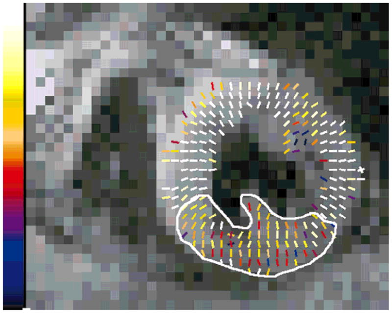
Strain map depicting myocardial lengthening. This map corresponds to the systolic function of the slice shown in Fig. 18. Maximum scale corresponds to 25% strain. The akinetic zone is depicted in the circumscribed area.
DISCUSSION
It has been demonstrated that displacement encoding by means of stimulated echoes provides functional data from the human heart (6). Our prior implementation (fast-DENSE) was based on Frahm et al.’s initial idea (18), but with segmented EPI readouts to shorten the acquisition widows. However, with fast-DENSE, the data acquisition period was too long for routine patient use and the images lacked sufficient SNR to cover the whole range of cardiac contraction/dilation. Due to the high encoding strengths used to remove unwanted signal contributions, intravoxel dephasing accentuated the problem, thus limiting the displacement-encoding period to a fraction of systole. Increasing the SNR would lift both these limitations. To achieve this, the entire STEAM signal needs to be recalled onto the transverse plane with a 90° pulse. Then, to shorten the acquisition time, the transverse magnetization must be sampled multiple times by means of multiple gradient echoes or spin echoes. Therefore, EPI and FSE readouts were considered for sampling the signal. For the heart, EPI was quickly discarded as a potential solution to this problem. Among the main concerns were a short relaxation constant and susceptibility to artifacts. Tissue interfaces with air, especially in the posterior wall of the heart, create gradient fields that dephase the transverse magnetization quickly. Also, off-resonance artifacts can drastically reduce image quality. It has been shown that, depending on the k-space sampling scheme, the available window for acquiring data in the heart with EPI is less than 20 ms (19). Since 2D strain analysis with DENSE requires the acquisition of three images, such a short readout-window is unacceptable. This is especially true if reasonably short breath-hold scans are expected for patient use. With FSE, the readout window can be significantly longer since T2 governs this decay process. However, this method is not suitable for acquiring phase-sensitive data due to the creation of local stimulated echoes by the imperfect 180° pulses of the FSE train (16). Such stimulated echoes result in prominent image artifacts because they interfere with the spin echoes. Rather than using a phase-insensitive preparation to create artifact-free images by isolating the MG component of the signal (12), we observe that the STEAM signal is a pure MG signal. As shown in the Theory section, the local stimulated echoes created by the imperfect refocusing pulses are constructively added to their corresponding part of the displacement-encoded STEAM signal. This is possible because the position-encoded STEAM signal contains both the original and its complex conjugate at equal weights. Note that neither of these two components is truly spin-echo-like, since they are both symmetrically contaminated by S1. Due to the nature of the STEAM signal, this approach does not require an additional phase-insensitive preparation. It already satisfies the conditions described by Alsop (12). This, along with balancing the gradient waveforms (0th-order moment nulling) during each 180–180 interval results in successful removal of artifacts related to violations of the Carr-Purcell-Meiboom-Gill (CPMG) condition. This would not have been possible if the second position-encoding gradient pulse was applied prior to the readout train of refocusing pulses. The only consequence of having imperfect refocusing pulses is some signal loss along the echo train. The long echo trains that are achieved result in significantly reduced data acquisition times. As such, meta-DENSE can be applied to patient studies, which require short breath-holds.
A major boost to image resolution is provided through the suppression of the unencoded FID by means of an inversion pulse during TM. This scheme removes through-slice crusher gradients that are the primary source of intravoxel dephasing signal losses. The removal of the FID signal also improves image resolution without increasing the displacement-encoding gradient for separating the STEAM signal components, which can potentially interfere and create image artifacts.
The control experiments performed in normal volunteers with meta-DENSE gave a strain noise level (2.1%) that is low enough to permit the diagnosis of functional deficits. The strain analysis is straightforward on groups of four neighboring pixels. As a result, strain visualization can be done on the fly. This process has been automated and no user interaction is needed. The intravoxel dephasing of the signal that originates from the blood results in blood-pool suppression (6). This allows for automatic segmentation of the myocardium by simple threshold-based algorithms. This could be further facilitated by chemical-shift fat suppression, during the encoding period, which results in the reduction of high-amplitude signal contributions, especially from areas adjacent to the phased-array receive coil. However, the applicability of a chemical-shift-based approach in the heart could be hampered by the susceptibility-induced field inhomogeneity.
In conclusion, meta-DENSE is optimized for patient use and on-the-fly feedback for clinicians. Stimulated-echo-based phase-contrast functional imaging with DENSE is now practical for clinical applications.
Acknowledgments
We acknowledge Dan Rettmann’s contributions to our processing software package.
References
- 1.Callaghan PT. Principles of nuclear magnetic resonance microscopy. Oxford: Clarendon Press; 1991. p. 430. [Google Scholar]
- 2.Aletras AH, Balaban RS, Wen H. Human heart imaging with dual-echo DENSE. Proceedings of the 8th Annual Meeting of ISMRM; Denver. 2000. [Google Scholar]
- 3.Aletras AH, Ding S, Balaban RS, Wen H. DENSE: displacement encoding with stimulated echoes in cardiac functional MRI. J Magn Reson. 1999;137:247–252. doi: 10.1006/jmre.1998.1676. [DOI] [PMC free article] [PubMed] [Google Scholar]
- 4.Chenevert TL, Skovoroda AR, O’Donnell M, Emelianov SY. Elasticity reconstructive imaging by means of stimulated echo MRI. Magn Reson Med. 1998;39:482–490. doi: 10.1002/mrm.1910390319. [DOI] [PubMed] [Google Scholar]
- 5.Reese TG, Wedeen VJ, Weisskoff RM. Measuring diffusion in the presence of material strain. J Magn Reson B. 1996;112:253–258. doi: 10.1006/jmrb.1996.0139. [DOI] [PubMed] [Google Scholar]
- 6.Aletras AH, Balaban RS, Wen H. High-resolution strain analysis of the human heart with fast-DENSE. J Magn Reson. 1999;140:41–57. doi: 10.1006/jmre.1999.1821. [DOI] [PubMed] [Google Scholar]
- 7.Fischer SE, Stuber M, Scheidegger MB, Boesiger P. Limitations of stimulated echo acquisition mode (STEAM) techniques in cardiac applications. Magn Reson Med. 1995;34:80–91. doi: 10.1002/mrm.1910340113. [DOI] [PubMed] [Google Scholar]
- 8.Chenevert TL, Steele DD, Emelianov SY, Skovoroda AR. Three-dimensional static displacement stimulated-echo NMR strain imaging. Proceedings of the 7th Annual Meeting of ISMRM; Philadelphia. 1999. [Google Scholar]
- 9.Steele DD, Chenevert TL, Skovoroda AR, Emelianov SY. Three-dimensional static displacement, stimulated echo NMR elasticity imaging. Phys Med Biol. 2000;45:1633–1648. doi: 10.1088/0031-9155/45/6/316. [DOI] [PubMed] [Google Scholar]
- 10.Norris DG, Bornert P, Reese T, Leibfritz D. On the application of ultra-fast RARE experiments. Magn Reson Med. 1992;27:142–164. doi: 10.1002/mrm.1910270114. [DOI] [PubMed] [Google Scholar]
- 11.Stejskal EO, Tanner JE. Spin diffusion measurements: spin echoes in the presence of a time-dependent field gradient. J Chem Phys. 1965;42:288–292. [Google Scholar]
- 12.Alsop DC. Phase insensitive preparation of single-shot RARE: application to diffusion imaging in humans. Magn Reson Med. 1997;38:527–533. doi: 10.1002/mrm.1910380404. [DOI] [PubMed] [Google Scholar]
- 13.Carr HY, Purcell EM. Effects of diffusion on free precession in nuclear magnetic resonance experiments. Phys Rev. 1954;94:630–638. [Google Scholar]
- 14.Schick F. SPLICE: sub-second diffusion-sensitive MR imaging using a modified fast spin-echo acquisition mode. Magn Reson Med. 1997;38:638–644. doi: 10.1002/mrm.1910380418. [DOI] [PubMed] [Google Scholar]
- 15.Zhu JM, Smith IC. Stimulated anti-echo selection in spatially localized NMR spectroscopy. J Magn Reson. 1999;136:1–5. doi: 10.1006/jmre.1998.1621. [DOI] [PubMed] [Google Scholar]
- 16.Wan X. Reduction of phase error ghosting artifacts in thin slice fast spin-echo imaging. Magn Reson Med. 1995;34:632–638. doi: 10.1002/mrm.1910340422. [DOI] [PubMed] [Google Scholar]
- 17.Kim RJ, Chen EL, Lima JA, Judd RM. Myocardial Gd-DTPA kinetics determine MRI contrast enhancement and reflect the extent and severity of myocardial injury after acute reperfused infarction. Circulation. 1996;94:3318–3326. doi: 10.1161/01.cir.94.12.3318. [DOI] [PubMed] [Google Scholar]
- 18.Frahm J, Hanicke W, Bruhn H, Gyngell ML, Merboldt KD. High-speed STEAM MRI of the human heart. Magn Reson Med. 1991;22:133–142. doi: 10.1002/mrm.1910220114. [DOI] [PubMed] [Google Scholar]
- 19.Epstein FH, Arai AE. Optimization of fast cardiac imaging using an echo-train readout. J Magn Reson Imaging. 2000;11:75–80. doi: 10.1002/(sici)1522-2586(200002)11:2<75::aid-jmri1>3.0.co;2-p. [DOI] [PubMed] [Google Scholar]