Abstract
Labeling of cells with nanoparticles for living detection is of interest to various biomedical applications. In this study, novel fluorescent/magnetic nanoparticles were prepared and used in high-efficient cellular imaging. The nanoparticles coated with the modified chitosan possessed a magnetic oxide core and a covalently attached fluorescent dye. We evaluated the feasibility and efficiency in labeling cancer cells (SMMC-7721) with the nanoparticles. The nanoparticles exhibited a high affinity to cells, which was demonstrated by flow cytometry and magnetic resonance imaging. The results showed that cell-labeling efficiency of the nanoparticles was dependent on the incubation time and nanoparticles’ concentration. The minimum detected number of labeled cells was around 104by using a clinical 1.5-T MRI imager. Fluorescence and transmission electron microscopy instruments were used to monitor the localization patterns of the magnetic nanoparticles in cells. These new magneto-fluorescent nanoagents have demonstrated the potential for future medical use.
Keywords: Magnetic nanoparticle, Fluorescence, Chitosan, Magnetic resonance imaging
Introduction
Magnetic iron oxide nanoparticles (MIONPs) have been extensively utilized for drug delivery, magnetic resonance imaging (MRI), hyperthermia techniques, cell separation, and tissue repair [1-5]. Especially, when used as a contrast agent for the MRI, MIONPs allow researchers and clinicians to enhance the tissue contrast of an area of interest by increasing the relaxation rate of water. Although native MIONPs appear to be the currently preferred cell-labeling materials, the relatively poor signal intensity of MIONPs on MRI limits their clinical utility. Hence, more efficient cellular-internalizing methods are highly preferable. Recent studies on the size effect [6,7], surface chemistry [8,9], targeting ligands [10], and assemblies of MIONPs under magnetic field [11] have been reported to improve the internalization of the contrast agent. However, the internalizing efficiency is still generally low as manifested by the requirement of a long-term incubation or a high concentration of particles with cells.
The stabilized MNPs in aqueous solutions are promising candidates for biomedical applications. One possible way is to encapsulate them with polymeric materials. Ideally, this polymeric material should be biocompatible and possess reactive functional groups for the further attachment of biomolecules. Chitosan is a natural poly-cationic polymer that has one amino group and two hydroxyl groups in the repeating hexosaminide residue. It is an ideal polymer in biological applications owing to their being hydrophilic, biocompatible, biodegradable, non-antigenic and nontoxic [12,13]. In addition, chitosan is known to facilitate drug delivery across cellular barriers and transiently open the tight junctions between epithelial cells [14].
Fabrication of magnetic and optical imaging into a nanostructured system would greatly benefit in disease diagnosis in vivo as well as monitoring of living cells in situ [15-17]. Fluorescent dye molecules and quantum dots (QDs) are most predominantly used for biological staining and optical labeling [18-23]. Considerable research has been devoted to the combination of magnetic and fluorescent properties in a single nanocomposite, which could act as multi-targeting, multi-functional, and multi-treating tools. However, the synthetic procedure in previous studies requires the multi-step chemical treatments. Thus, we synthesize a simple and stable nanoprobe that exhibits magnetic and fluorescence properties for detection of cancer cell. The chemical synthesis is based on the covalent coupling of modified organic fluorophores with chitosan, which strongly interact with the surface of the ferric oxide nanoparticles (Fig. 1). The high cellular affinity and imaging efficacy of the nanoparticles have extensively been investigated using MRI and optical imaging.
Figure 1.

Schematic diagram of preparation of FITC-CS@MNPs
Experiments
Preparation and Characterization of FITC-Labeled Chitosan Nanoparticles
The synthesis of FITC-labeled chitosan was based on the reaction between the isothiocyanate group of FITC and the primary amino group of chitosan [24]. The FITC of 20 mg in 20 ml dehydrated methanol was added to 20 ml 1% w/v chitosan (low molecular, Sigma-Aldrich.) in 0.1 M acetic acid solution. After 3 h of reaction in the dark at ambient temperature, the FITC-labeled chitosan (FITC-CS) was precipitated by raising the pH to 10 with 0.5 M NaOH. The unreacted FITC was washed with distilled water and separated by centrifuge until no fluorescence was detected in the suspernatant. The FITC-CS dissolved in 20 ml 0.1 M acetic acid was then dialyzed in 4 l of distilled water for 3 days under darkness, with water being replaced every day.
Fe3O4 nanoparticles were synthesized by chemical coprecipitation of Molday. In typical synthesis, a mixture solution of FeCl3 and FeSO4 (molar ratio 2:1) was prepared under N2 shielding and then enough ammonia aqueous solution was poured into it while violently stirring. The black precipitate was formed and washed several times with deionized water. The final magnetite nanoparticles were dispersed in deionized water with pH 3.0 and oxidized into more stable maghemite (γ-Fe2O3, MNPs) by air at the temperature of 90°C. During this step, the initial black slurry turning into brown could be observed [25]. After that, MNPs were coated with FITC-CS (FITC-CS@MNPs), and 4 ml of above FITC-CS acetic acid solution was added to 50 ml of MNPs solution. The mixture was stirred for 4 h and then washed by the above magnetic separation method to remove dissociative FITC-CS.
Characterization of Magnetic Particles
The magnetic measurements were carried out using a Vibrating Sample Magnetometer (VSM, Lakeshore 7407, USA). The zeta potentials of the particles were determined by Zeta Potential Analyzer (BECKMAN, Delsa 440SX, USA). The particle morphology and size of the samples were determined by transmission electronic microscopy (TEM, JEOL, JEM-200EX). The emission spectra were measured with a Hitachi FL4500. The emission absorption spectra were measured using a LS-55 spectrophotometer (PerkinElmer, USA).
Cell Culture
Human hepatoma cell line, SMMC-7721, was provided by Shanghai Cellular Institute of China Scientific Academy. Cells were cultured in RPMI 1640 medium containing 10% fetal calf serum (FCS), 100 μg/ml penicillin, and 100 μg/ml streptomycin. For control experiments, medium having no particle was used. The cells were incubated at 37°C in 5% CO2atmosphere and medium was replaced every other day.
Cellular Uptake Experiments
In the cell-uptake experiments, the cells were incubated with different concentrations of FITC-CS@MNPs suspension in medium for various incubation times. After indicated times, the cells were washed three times with 0.1 M PBS, then harvested by trypsinization, centrifuged, and resuspended in 0.1 M PBS or 0.5 ml of 1% agarose in Eppendorf tubes. Cellular uptake of FITC-CS@MNPs was determined semiquantitatively by the incorporated fluorescence intensity and MR functionalities, using a BD FACS Calibur flow cytometry (BD Biosciences, Franklin Lakes, NJ, USA) and a clinical 1.5-T MRI System (Eclipse, Philips Medical Systems, The Netherlands) by using a 12.7-cm receive-only surface coil, respectively.
The fluorescence of NBD- labeled green marker compounds was measured with a 488-nm argon laser excitation and a 530/30 bandpass filter for emissions. The whole amounts of cell surface uptake level and the intracellular uptake level were qualified by converting to an average number of molecules per cell.
The sequence parameters for T1-weighted (T1 W) imaging was spin-echo repetition time 500 ms, echo time 17.9 ms; T2-weighted (T2 W) imaging was fast spin-echo repetition time 4000 ms; echo time 108 ms; echo train length 16; T2*-weighted (T2*W) imaging was gradient-echo repetition time 620 ms, echo time 15.7 ms; flip angle 35°. Images were obtained with a matrix size of 256 × 256—two measurements were acquired: section thickness of 2 mm; field of view of 10 × 10 cm. Region of interest for signal intensity measurement was 20 mm2. These tubes contained 5 × 10², 1 × 10³, 5 × 10³, 1 × 104,5 × 104,1 × 105labeled cells, respectively. Another two Eppendorf tubes containing 1 × 10⁶unlabeled cells and distilled water were used.
Fluorescent and Transmission Electron Microscopy
After magnetic nanoparticles labeling, adhering cells were washed three times with 0.1 M PBS and then fixed with 2% glutaraldehyde buffered in 0.1 M PBS for 1 h at 4°C. The optical and fluorescent images were observed with an Axioskop 200 microscope equipped with a Coolsnap MP3.3 camera (Carl Zeiss, Germany).
For the samples of TEM, the cells were washed three times with 0.1 M PBS, then harvested by trypsinization, centrifuged, and fixed with 2% glutaraldehyde buffered in 0.1 M PBS for 1 h at 4°C. The cells were then post-fixed in 1% osmium tetroxide for 2 h at 4°C, washed again with PBS, dehydrated through a series of alcohol concentrations (20, 30, 40, 50, 60, 70%), and followed by further dehydration(90, 96, 100% and dry alcohol). The cells were finally treated with propylene oxide followed by 1:1 propylene oxide: resin for overnight to evaporate the propylene oxide. The cells were subsequently embedded in Araldite resin, and ultra-thin sections cut with glass knives were stained with lead nitrate, and viewed under a HITACHIH-600 electron microscope at 80 kV.
In Vitro Cell-Viability/Cytotoxicity Studies
To determine cell cytotoxicity/viability, the cells were plated at a density of 1 × 10⁴cells/well in 96-well plates at 37°C in 5% CO2atmosphere. After 24 h of culture, the medium in the wells was replaced with the fresh medium containing nanoparticles in the concentration range of 0–123.52 μg/ml. After 12 h, the medium was removed and rinsed twice with medium, and then 20 μl of MTT (3,4,5-dimethylthiazol-yl-2,5-diphenyl tetrazolium, Sigma) dye solution (5 mg/ml in medium) was added to each well. After 4 h of incubation at 37°C, the medium was removed, and Formazan crystals were dissolved in 200 μl dimethylsulphoxide (DMSO) and quantified by measuring the absorbance of the solution at 570 nm by a microplate reader (Model 680, Bio-RAD). The spectrophotometer was calibrated to zero absorbance, using culture medium without cells. The relative cell viability (%) related to control wells containing cell culture medium without nanoparticles was calculated by [A]test/[A]control × 100, where [A]test is the absorbance of the test sample and [A]control is the absorbance of control sample.
Statistical Analysis
Each experiment was repeated three times in duplicate. The results were presented as mean ± SD. Statistical significance was accepted at a level ofP < 0.05.
Results and Discussion
Characterize of FITC-CS@MNPs
A representative hysteresis loop of FITC-CS@MNPs at ambient temperature is shown in Fig. 2. The saturation magnetization of the FITC-CS@MNPs was about 53.47 emu/g, while that of naked MNPs was about 55.52 emu/g. The decrease of the saturation magnetization was most likely attributed to the existence of coated materials on the surface of MNPs.
Figure 2.
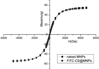
Magnetization curves of naked MNPs and FITC-CS@MNPs
The electrostatic interaction of the nanoparticles can be controlled by variation in their surface charges, which can be determined by measuring the zeta potential of these particles. Figure 3 illustrated the zeta potential of naked MNPs and FITC-CS@MNPs as a function of pH. It showed that the zeta potential of naked MNPs and FITC-CS@MNPs was positive at lower pH and negative at higher pH [26]. Compared with naked MNPs, the zeta potential of FITC-CS@MNPs possessed higher positive charge at physiological environment (pH = 7.4), which favored the association to the negative domain of cell membrane. IEP of FITC-CS@MNPs was about 9.7 where the net charge of surface is zero.
Figure 3.
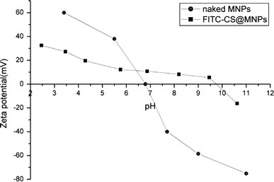
pH-dependent zeta potential curves of naked MNPs and FITC-CS@MNPs
The size and morphology of the FITC-CS@MNPs were investigated by TEM (Fig. 4a). The particle size and size distribution of these particles were calculated with at least 200 particles chosen at random in all the prepared samples through an image analysis program. Most of FITC-CS@MNPs were quasispherical and with an average diameter of 13.8 ± 5.3 nm. The nanoparticles can form a stable dispersion in neutral water for several months without noticeable precipitation. The electron-diffraction pattern recorded from these spheres confirmed that magnetite nanoparticles were coated successfully. A salient feature of Fig. 4c is that these nanoparticles have an intense dark circle within the shells of the spheres and dark spots at the surface of some spheres, which suggests that the distribution of the γ-Fe2O3nanoparticles is not concentrated in the core of the spheres, which corresponds well to the size of the used γ-Fe2O3nanoparticles.
Figure 4.
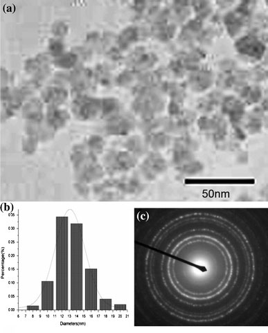
TEM images of (a) FITC-CS@MNPs, (b) mean size = 13.8 ± 5.3 nm, and (c) Electron-diffraction pattern of FITC-CS@MNPs
The fluorescent properties of FITC-CS@MNPs were investigated with the excitation peak in 488 nm. As can be seen from Fig. 5, the FITC-CS@MNPs exhibited an intense and narrow emission spectrum with a peak at 520 nm, similar to that of FITC with a peak at 518 nm (Fig. 5). The small red-shift (2 nm) resulted from the surrounding environments of the amino groups or the interaction between the dye and the oxide nanoparticles, which was also reported in previous studies [23]. The fluorescence intensity of the FITC-CS@MNPs was lower than that of FITC-CS. This may be due to the quenching when fluorescence contacted MNPs surface and the possible energy transfer occurring with metal oxide particles. Nevertheless, there was still sufficient emission for biological imaging. The strong and stable fluorescence of the FITC-CS@MNPs provided a visual detection method for cell labeling and monitoring their location in body.
Figure 5.
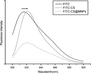
Emission spectra (λex = 488 nm) of FITC, FITC-CS, and FITC-CS@MNPs
Cellular Uptake
To examine the cell-labeling efficiency, SMMC-7721 cells were incubated with various concentrations of FITC-CS@MNPs for 2 h and different labeling times of FITC-CS@MNPs (15.44 μg). In control experiments, medium having no particle was used. We found FITC-CS@MNPs uptake was dose- (1.93, 3.86, 7.72, 15.44, and 30.88 μg) and time-(0.5, 1, 2, 4, and 8 h) dependent. In the flow cytometry data (Fig. 6), the histograms of fluorescence intensity of cells that were incubated with various concentrations of FITC-CS@MNPs for 2 h were displayed, and data showed that the number of labeled cells and the mean value of fluorescence intensity followed the incubation concentration of FITC-CS@MNPs. When the FITC-CS@MNPs (7.72 μg) were incubated with the cells, more than 85% of cells were labeled. As shown in the Fig. 7, the uptake of FITC-CS@MNPs began significantly as early as 30 min after incubation with 15.44 μg of nanoparticles, and was relatively more rapid within the first 2 h of incubation. As time elapsed, it became a cumulative process. This indicated cells can be labeled efficiently within a short incubation time by using a relatively low dose of FITC-CS@MNPs.
Figure 6.
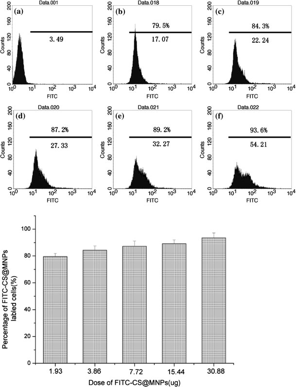
Flow cytometric analysis of SMMC-7721 cells when incubated with different dosages (1.93 μg (b), 3.86 μg (c), 7.72 μg (d), 15.44 μg (e) and 30.88 μg (f)) of FITC-CS@MNPs. In control experiments, medium having no particle was used (a). The mean fluorescence intensity of FITC-CS@MNPs labeled cells was noted below the line and the percentage of labeled cells was noted above the line. The number of positively labeling cells (defined as the fluorescence value >101) was represented as the percentage of total counting cells in each panel. The histogram showed that there was the percentage of labeled cells under different dosage of FITC-CS@MNPs
Figure 7.
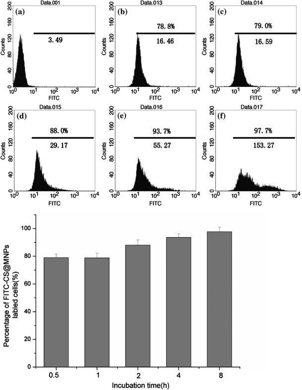
Flow cytometric analysis of SMMC-7721 cells when incubated with FITC-CS@MNPs for a definite time (0.5 h (b), 1 h (c), 2 h (d), 4 h (e), 8 h (f)). In control experiments, medium having no particle was used (a). The mean fluorescence intensity of FITC-CS@MNPs labeled cells was noted below the line and the percentage of labeled cells was noted above the line. The number of positively labeling cells (defined as the fluorescence value >101) was represented as the percentage of total count of the cells in each panel. The histogram showed the percentage of labeled cells when treated with FITC-CS@MNPs for a definite time
Using a clinical 1.5-T MR imager, the MR images of samples in Eppendorf tubes were detected. Under T2* weighted image mode (T2*WI), cells exposed to 15.44 μg of FITC-CS@MNPs for 2 h could be easily detected (Fig. 8). These MRI measurements were consistent with the results obtained through flow cytometry studies. It implied that through the high cellular labeling efficiency of FITC-CS@MNPs, a small number of SMMC-7721 was easily imaged with a short-term incubation using a clinical 1.5-T MR imager. To investigate the limit of labeling, a series of diluted labeled cells were investigated for MRI. Figure 7 showed the MR images of FITC-CS@MNPs could be distinguishably observed at the cell numbers of around 104. The minimum number of cells detected was around 5 × 10³ to 1 × 10⁴. No signal intensity difference was observed from the unlabeled control group. It was reported that the SPIO@SiO2(FITC) nanoparticles could detect about 1 × 10⁴ cells after treatment with 30 μg/ml nanoparticles for 1 h under 1.5-T MR imager [27]. And, labeling of the human umbilical cord blood mesenchymal stem cells (MSCs) with 20 μg/ml poly-l-lysine@SPIO, T2*WI demonstrated significant decrease of signal intensity in vials containing 1 × 10⁶ (1 day), 1 × 10⁶ (8 days), and 5 × 10⁵ labeled cells, in comparison with the unlabeled cells to obtain MRI of the labeled MSCs’ suspension at 1.5 T [28]. Thus the FITC-CS@MNPs had high cellular affinity and low detection threshold of cell number.
Figure 8.
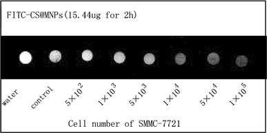
T2* imaging of different number cells when labeled with FITC-CS@MNPs in vitro. Cells ranging from 5 × 10²to 1 × 10⁵after treatment with 15.44 μg FITC-CS@MNP for 2 h were scanned. Unlabeled cells of identical numbers and distilled water were scanned as a control group
In order to clarify the location of the magnetic nanoparticles in the cells, we performed fluorescence microscopy and electron microscopy. We observed that the magnetic particles were located inside the cells as well as on the cell surface (Fig. 9). Hence, binding a fluorescent dye onto magnetic nanoparticles enabled their direct imaging and localization in living cells. TEM provided an even higher resolution than optical imaging. Nanoparticles were internalized within the cell inside late endosomes or lysosomes (Fig. 10). Particles were exclusively present in the form of agglomerates. No uptake into endoplasmatic reticulum, mitochondria and structures of the Golgi organ or the nucleus was found. The accumulation of coated particles within lysosomes was also described by others [29,30].
Figure 9.
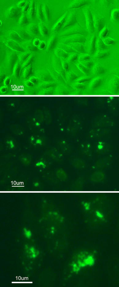
Fluorescent images of SMMC-7721 cells when incubated with (a) Control; (b), (c) FITS-CS@MNPs for 8 h
Figure 10.
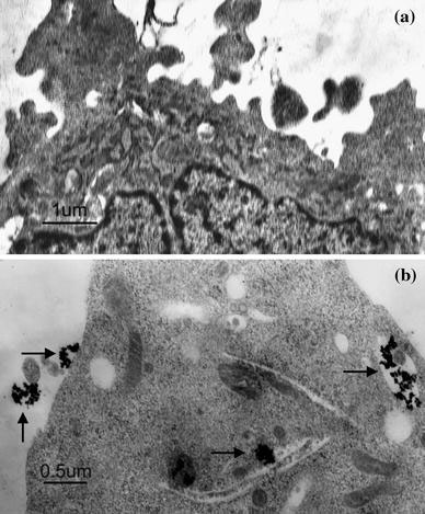
TEM images of SMMC-7721 cells when incubated with (a) Control; (b) FITS-CS@MNPs for 8 h. Black arrow pointed to MNPs
Chitosan, which has a positive zeta potential, can interact with negative domain of cell membranes by nonspecific electrostatic interactions [13,14]. FITC-CS@MNPs, with their tiny size and positive surface charge, showed a high electrostatic affinity for the cell membrane. Cellular internalization was initiated by nonspecific interactions between nanoparticles and cell membranes. It was reported that A549 cell uptake of chitosan nanoparticles occurred predominantly by adsorptive endocytosis, mediated in part by clathrin, but not by passive diffusion or by fluid-phase endocytosis [9]. Cellular uptake of N-acetyl histidine-conjugated glycol chitosan self-assembled nanoparticles also was reported to internalize by adsorptive endocytosis [31]. There were no reports of chitosan-specific receptors on cell membranes.
In Vitro Cell-Viability and Cytotoxicity Studies
To evaluate the biocompatibility of FITC-CS@MNPs as imaging probes, we investigated the cytotoxicity of FITC-CS@MNPs using the MTT assay. The MTT assay relies on the mitochondrial activity of cells and represents a parameter for their metabolic activity. Figure 11 demonstrates a dose-dependent reduction in MTT absorbance for cells treated with FITC-CS@MNPs and naked MNPs. After having been incubated for 12 h, FITC-CS@MNPs caused a minor reduction (about 10% of control) in cell viability and exhibited low cytotoxicity towards SMMC-7721 even at high dose (123.52 μg). Naked MNPs caused a significant reduction (90% of control) in cell viability even when tested at the lowest concentration (0.01 mg/ml), and induced further reductions at higher concentrations; it resulted in about 65% loss of cell viability when tested at the higher concentration (0.16 mg/ml). Y. Wang [32] and A. K. Gupta [33] et al. had investigated the cell viability of Resovist (commercial iron oxides) and uncoated iron oxide nanoparticles, respectively. Both these nanoparticles caused a significant reduction in cell viability even when tested at the lowest concentration tested. It seemed that our magnetite nanoparticles were highly biocompatible and safe for further in vivo use.
Figure 11.
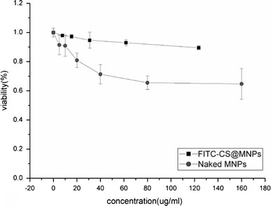
Cytotoxicity curves of naked MNPs and FITC-CS@MNPs when incubated with SMMC-7721 cells as determined by MTT assay
Conclusions
A novel magnetic fluorescent nanoparticle was prepared by a simple synthesis method and used for high-efficient labeling cancer cell. The FITC-CS@MNPs described here could be efficiently internalized into SMMC-7721 because of their electrostatic interactions with the cell membrane. These labeled cells can be visualized in a clinical 1.5-T MRI imager with detectable cell numbers of about 104in vitro. Magnetic fluorescent nanoparticles serve both as magnetic resonance contrast agents for MRI and optical probes for intravital fluorescence microscopy. Cytotoxicity test demonstrated that the prepared FITC-CS@MNPs possessed a suitable property for biomedical application.
Acknowledgments
This research has been carried out under the financial grants from The National Natural Science Foundation of China (Nos. 60571031, 60501009, and 90406023) and The National Basic Research Program of China (Nos. 2006CB933206 and 2006CB705600).
References
- Won J, Kim M, Yi Y, Kim YH, Jung N, Kim TK. Science. 2005. p. 121. COI number [1:CAS:528:DC%2BD2MXlsF2htro%3D]; Bibcode number [2005Sci...309..121W] [DOI] [PubMed]
- Weissleder R. Science. 2006. p. 1168. COI number [1:CAS:528:DC%2BD28XkvVOitbc%3D]; Bibcode number [2006Sci...312.1168W] [DOI] [PubMed]
- Huh Y, Jun Y, Song H, Kim S, Choi J, Lee J, Yoon S, Kim K, Shin J, Suh J, Cheon J. J. 2005. p. 12387. COI number [1:CAS:528:DC%2BD2MXnslOrtbw%3D] [DOI] [PubMed]
- Corot C, Robert P, Port M. Adv. 2006. p. 1471. COI number [1:CAS:528:DC%2BD28Xht1KmtLbP] [DOI] [PubMed]
- Ma M, Wu Y, Zhou J, Sun Y, Zhang Y, Gu N. J. 2004. p. 33. COI number [1:CAS:528:DC%2BD3sXosFyjs7s%3D]; Bibcode number [2004JMMM..268...33M] [DOI]
- Jun Y, Huh Y, Choi J, Lee J, Song H, Kim S, Yoon S, Kim K, Shin J, Suh J, Cheon J. J. 2005. p. 5732. COI number [1:CAS:528:DC%2BD2MXivVert7o%3D] [DOI] [PubMed]
- Win KY, Feng S. Biomaterials. 2005. p. 2713. COI number [1:CAS:528:DC%2BD2cXhtVChsrvP] [DOI] [PubMed]
- Yuan JJ, Armes SP, Takabayashi Y, Prassides K, Leite C, Galembeck F, Lewis AL. Langmuir. 2006. p. 10989. COI number [1:CAS:528:DC%2BD28Xht1WksLbL] [DOI] [PubMed]
- Huang M, Ma Z, Khor E, Lim L. Pharm. 2002. p. 1488. COI number [1:CAS:528:DC%2BD38XnsFSgsbg%3D] [DOI] [PubMed]
- Benjamin T, Al-Ejeh F, Brown MP, Majewski P, Griesser HJ. Adv. 2008. p. 1. [DOI]
- Sun J, Zhang Y, Chen Z, Zhou J, Gu N. Angew. 2007. p. 4767. COI number [1:CAS:528:DC%2BD2sXntlOksro%3D] [DOI] [PubMed]
- Weecharangsan W, Opanasopit P, Ngawhirunpa T, Apirakaramwong A, Rojanarata T, Ruktanoncha U, Lee RJ. Int. 2008. p. 161. COI number [1:CAS:528:DC%2BD2sXhsVGlurvF] [DOI] [PubMed]
- Jain S, Sharma RK, Vyas SP. J. 2006. p. 303. COI number [1:CAS:528:DC%2BD28XpsFKgsrk%3D] [DOI] [PubMed]
- Dodane V, Khan MA, Merwin JR. Int. 1999. p. 21. COI number [1:CAS:528:DyaK1MXjtVyksrw%3D] [DOI] [PubMed]
- Corr SA, Rakovich YP, Gun’ko YK. Nanoscale Res. 2008. p. 87. COI number [1:CAS:528:DC%2BD1cXlslejt7k%3D]; Bibcode number [2008NRL.....3...87C] [DOI]
- Bertorelle F, Wilhelm C, Roger J, Gazeau F, Ménager C, Cabuil V. Langmuir. 2006. p. 5385. COI number [1:CAS:528:DC%2BD28XktlKmurs%3D] [DOI] [PubMed]
- Gunn J, Wallen H, Veiseh O, Sun C, Fang C, Cao J, Yee C, Zhang M. Small. 2008. p. 712. COI number [1:CAS:528:DC%2BD1cXosFynt7s%3D] [DOI] [PMC free article] [PubMed]
- Lee H, Yu MK, Park S, Moon S, Min JJ, Jeong YY, Kang H, Jon S. J. 2007. p. 12739. COI number [1:CAS:528:DC%2BD2sXhtVOhtrvJ] [DOI] [PubMed]
- Wu Si, Lin Y, Hung Y, Chou Y, Hsu Y, Chang C, Mou C. Chembiochem. 2008. p. 53. COI number [1:CAS:528:DC%2BD1cXlt1Wiurs%3D] [DOI] [PubMed]
- Kumar R, Roy I, Ohulchanskyy TY, Goswami LN, Bonoiu AC, Bergey EJ, Tramposch KM, Maitra A, Prasad PN. ACSNANO. 2008. p. 449. COI number [1:CAS:528:DC%2BD1cXjtVCqsLg%3D] [DOI] [PubMed]
- Qiu G, Xu Y, Zhu B, Qiu G. Biomacromolecules. 2005. p. 1041. COI number [1:CAS:528:DC%2BD2MXhtF2jsbw%3D] [DOI] [PubMed]
- Mulder WJM, Koole R, Brandwijk RJ, Storm G, Chin PTK, Strijkers GJ, de Donegá CM, Nicolay K, Griffioen AW. Nanoletters. 2006. p. 1. COI number [1:CAS:528:DC%2BD2MXht1ertL%2FN] [DOI] [PubMed]
- Li L, Chen D, Zhang Y, Deng Z, Ren X, Meng X, Tang F, Ren J, Zhang L. Nanotechnology. 2007. p. 1. COI number [1:CAS:528:DC%2BD2sXosVyjtb4%3D]
- Mi FL, Wu YY, Chiu YL, Chen MC, Sung HW, Yu SH, Shyu SS, Huang MF. Biomacromolecules. 2007. p. 892. COI number [1:CAS:528:DC%2BD2sXhvF2rtLo%3D] [DOI] [PubMed]
- Zhang S, Bian Z, Gu C, Zhang Y, He S, Gu N, Zhang J. Colloids Surf. B Biointerfaces. 2007. p. 143. COI number [1:CAS:528:DC%2BD2sXitFeku7o%3D] [DOI] [PubMed]
- Zhang S, Zhang Y, Liu J, Zhang C, Gu N, Li F. J. 2007. p. 1.
- Lu C, Hung Y, Hsiao J, Yao M, Chung T, Lin Y, Wu S, Hsu S, Liu H, Mou C, Mou C, Yang C, Huang D, Chen Y. Nano Lett. 2007. p. 149. COI number [1:CAS:528:DC%2BD28Xht1OmsL7P] [DOI] [PubMed]
- Ju S, Teng G, Zhang Y, Ma M, Chen F, Ni Y. Magn. Reson. Imaging. 2006. p. 611. [DOI] [PubMed]
- Wilhelm C, Gazeau F, Roger J, Pons JN, Bacri JC. Langmuir. 2002. p. 8148. COI number [1:CAS:528:DC%2BD38XmvVGmsLs%3D] [DOI]
- Lorenz MR, Holzapfel V, Musyanovych A, Nothelfer K, Walther P, Frank H. Biomaterials. 2006. p. 2820. COI number [1:CAS:528:DC%2BD28XhtVans7k%3D] [DOI] [PubMed]
- Park JS, Han TH, Lee KY, Han SS, Hwang JJ, Moon DH, Kim SY, Cho YW. J. Control Release. 2006. p. 37. COI number [1:CAS:528:DC%2BD28XpvVOht7c%3D] [DOI] [PubMed]
- Wang Y, Ng YW, Chen Y, Shuter B, Yi J, Ding J, Wang S, Feng S. Adv. 2008. p. 308. COI number [1:CAS:528:DC%2BD1cXhvVOmtrc%3D] [DOI]
- Gupta AK, Gupta M. Biomaterials. 2005. p. 1565. COI number [1:CAS:528:DC%2BD2cXptV2ltL0%3D] [DOI] [PubMed]


