Abstract
An efficient electromagnetic shielding composite based on multiwalled carbon nanotubes (MWCNTs)-filled styrene acrylic emulsion-based polymer has been prepared in a water-based system. The MWCNTs were demonstrated to have an effect on the dielectric constants, which effectively enhance electromagnetic shielding efficiency (SE) of the composites. A low conductivity threshold of 0.23 wt% can be obtained. An EMI SE of ~28 dB was achieved for 20 wt% MWCNTs. The AC conductivity (σac) of the composites, deduced from imaginary permittivity, was used to estimate the SE of the composites in X band (8.2–12.4 GHz), showing a good agreement with the measured results.
Keywords: Multiwalled carbon nanotubes, Electromagnetic interference shielding, Complex permittivity, Styrene acrylic emulsion
Introduction
Due to the quick growth in the utilization of commercial, industrial and military applications, EMI has become a serious concern in modern society. Light-weight EMI shielding is needed to protect the environment and workplace from EMI due to unwanted electromagnetic waves, especially for the building containing power transformers and other electronic facilities, which will radiate electromagnetic wave to the environment. Electrically conductive polymer composites containing carbon-based fillers have been extensively investigated recently for EMI shielding applications [1-3]. Compared to conventional metal-based EMI shielding materials, they are light weight, resistant to corrosion and flexible [4].
Recently, multiwalled carbon nanotubes (MWCNTs)/polymer conductive composites have received extensive considerable attentions in both fundamental and applied research fields. Previous studies on the MWCNTs and their diversified applications show that MWCNTs possess excellent electrical, mechanical properties and unique one-dimensional structure [5-10], which make them an ideal option to create overlapping conductive network for high-performance EMI shielding at low loadings [11-13]. Many MWCNTs/polymer composites in typical solutions or melt-based systems have been studied with various polymer matrix, including epoxy [14], shape memory polymer [15], poly(methyl methacrylate) (PMMA) [16], polyurethane [13], for various applications such as effective and light-weight EMI shielding, microwave absorption, high charge storage capacitors. However, the polymer composite materials with MWCNTs in water-based systems have been largely unexplored and more environmentally friendly, for there is no or negligible content of volatile organic compounds. It has been reported that the defective arc-made MWCNTs have a high dielectric constants [17], and the theory prediction shows that the lattice defects can create localized states near the Fermi level [18], which can give rise to large microwave absorption. The defects on the MWCNTs can be introduced by a special purification process [19-21].
Styrene acrylic emulsion is widely used in the field of the architectural paints for its prominent properties such as high resistance to UV light, oxygen, water, various types of solvents and excellent durability [22]. However, styrene acrylic emulsion-based polymer alone has a low conductivity and provides no shielding property. It seems reasonable to prepare styrene acrylic emulsion-based composites for building shielding materials by incorporating WMCNTs with all the excellent properties mentioned earlier.
In this study, we prepared a styrene acrylic emulsion-based composite with well-dispersed MWCNTs for building EMI shielding applications. The structural characteristics of the MWCNTs and composites were investigated through field-emission scanning microscopy (FESEM), high-resolution transmission electron microscopy (HRTEM) and Raman spectroscopy experiments. The DC conductivity (σdc), complex permittivity and EMI SE of the composites in 8.2–12.4 GHz were reported. The AC conductivity (σac) of the composites, calculated from imaginary permittivity, was used to estimate the SE of the composites in the far field.
Experimental Details
Material Treatments
The styrene acrylic emulsion (trade name HBC-03) used in this study was provided by Beijing Huyi Co., Ltd. This emulsion was approximately 48 ± 2 wt% solids in water. The minimum film formation temperature for this system is 15°C, and the glass transition temperature (Tg) is 34°C. The raw MWCNTs were supplied by Shanghai Jiaotong University (Shanghai, China). The diameter of the raw MWCNTs was 5–10 nm, the length was 5–10 μm, and the purity was 95%. They were synthesized by a chemical vapor deposition method using Ni as the main catalyst. The raw MWCNTs were subjected to chain-scission in a 3:1 mixture of sulfuric acid and nitric acid at 80°C for 2 h in a reflux system. The purified MWCNTs were then heated to 100°C under nitrogen atmosphere to evaporate excess acid and water. Anionic surfactant sodium dodecylbenzene sulfonate (SBDS) was introduced to stabilize the MWCNTs to obtain better dispersion.
Preparation of the Composites
The conventional solution process described below was used to prepare the composites. The purified MWMTs were first added into de-ionized water with 2.0 wt% SBDS in an ultrasonic bath with oscillation frequency of 42 kHz for 2 h at room temperature, and then the styrene acrylic emulsion was added to the suspension of purified MWNTs with designed weight ratios. The mixture was again sonicated for 2 h. The highest concentration of purified MWNTs in emulsion was mixed first, and lower concentrations were obtained by diluting the mixture with more emulsion and de-ionized water. The prepared mixture was coated onto concrete panels (60 cm × 60 cm × 5 cm) to measure the EMI SE. Some of the mixture was poured into casting molds. The samples were consolidated at ~50°C for 24 h. Then the samples were dried at room temperature until a constant weight was achieved. The thickness of the composite films was 1.5 mm. A series of styrene acrylic emulsion-based composite films were prepared with different mass concentrations of purified MWCNTs. The prepared samples were cut into the desired sizes for further measurements.
Property Characterization
The morphology and structure of the samples were studied with field-emission scanning electron microscope (FESEM, HITACHI S-4300), high-resolution transmission electron microscope (HRTEM, JEOL-2010) and Raman spectroscopy (Ramascope-1000, 514 nm laser). The composites were freeze-fractured in liquid nitrogen and gold coated before imagining on FESEM.
The dc electrical conductivity of the composites was measured with a four-point method at room temperature. The EMI SE of the composites in the X band was measured in an anechoic shielded room to simulate the actual conditions. The experimental configurations are sketched in Fig. 1. The set-up of SE measurement is composed of an anechoic shielded room, a Vector Network Analyzer (Hewlett-Packard HP 8563E), a sweep oscillator (Hewlett-Packard HP83640A), transmitting and receiving horn antennas. There are absorbers on the inside walls of an anechoic shielded room and an aperture in one wall, where the samples can be placed. The specimen size is 60 cm × 60 cm, which was calculated according to the “3-dB beam width” measurement. The complex permittivity of the composites was measured using slabs (22.86 mm × 10.16 mm × 2 mm) by a HP 8510C vector network analyzer in 8.2–12.4 GHz.
Figure 1.
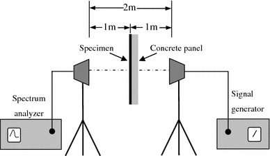
Schematic configuration of the EMI SE measurement set-up
Results and Discussion
Raman and Morphological Analysis
Figure 2a shows the Raman spectra of the raw and purified MWCNTs. The MWCNTs displayed two characteristics peaks in the spectra, the first at about 1,300 cm−1 assigned the D band and derived from the defects and disordered graphite structures, the second at 1,600 cm−1 assigned the G band and associated with tangential C–C bond stretching motions [23]. The ratio of the intensities of these two peaks (D:G) can give information about the quality of the tube structure [24], which increases from 0.116 for the raw MWCNTs to 0.644 for the purified MWCNTs, suggesting that many defects have been caused after the acid treatment and chain-scission. Figure 2b shows the HRTEM image of the purified MWCNTs. It revealed that the MWCNTs are multiwalled, and the Ni catalyst was enclosed within them, which still remained after purification and can induce charge tunneling in the conductive network [16]. Some of the amorphous carbon layers (indicated with arrows) are found on both the exterior and interior walls of the purified MWCNTs, indicating etching effects had been carried out during the purification process.
Figure 2.
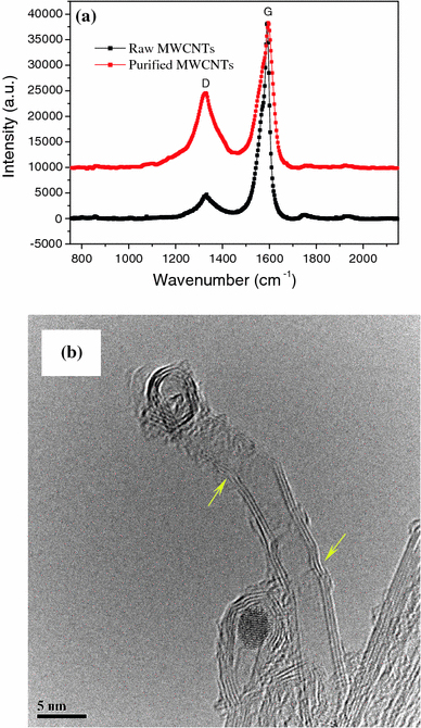
a Raman spectra of raw and purified MWCNTs. b HR-TEM image of the purified MWCNTs. The yellow arrows indicate the defects on the MWCNTs
Figure 3a shows the FESEM image of the MWCNTs. As we can see, the MWCNTs are weaved and tangled with each other. There is variation on the diameter of the MWCNTs. Figure 3b shows a representative microphotograph of the freeze-fractured surface of the styrene acrylic emulsion-based composites with 2 wt% purified MWCNTs. Individual purified MWCNTs are homogeneously dispersed and embedded in the polymer matrix (indicated by arrows). The microstructure of the composites shows a good wetting between the purified MWCNTs and the styrene acrylic polymer matrix. This can be explained by the disentanglement of the purified MWCNTs and subsequent penetration of styrene acrylic emulsion into the purified MWCNTs bundles during the ultrasound dispersion process.
Figure 3.
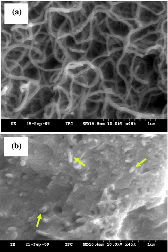
a FESEM image of the MWCNTs. b FESEM image of the cross-section of styrene acrylic emulsion-based composites with 2 wt% MWCNTs. The yellow arrows indicate the MWCNTs dispersed in the polymer matrix
Electrical Properties
Further evidence for efficient dispersion and interconnectivity of MWCNTs in the polymer matrix was obtained from the dc conductivity of the composites. Figure 4 shows σdc of styrene acrylic emulsion-based composites as a function of MWCNTs concentrations (p) in logarithmic scale at room temperature. The inset of Fig. 4 is plot of σdc as a function of p in linear scale. The results show that the σdc obeys the power law relationship around the percolation threshold [23], as shown in Eq. 1:
Figure 4.
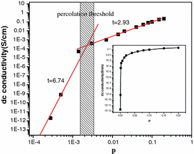
The dc conductivity (σdc) versus mass fraction (p) of purified WMCNTs-added styrene acrylic emulsion-based composite in log–log scale. Inset: plot of σdc as a function of p in linear scale
where σ is the composite conductivity, v is the MWCNTs volume fraction, vc is the percolation threshold volume fraction, t is the critical exponent. Due to the uncertainty of the MWCNTs density and the mass fraction is very similar to volume fraction for this system, the mass fraction of MWCNTs (p) is preferred instead of the volume fraction (v) in the current experiment. As we can see in Fig. 4, the slope, i.e., the critical exponent t in Eq. 1 varied from 6.74 to 1.93, implying a percolation threshold nearly 0.23 wt%, which has been highlighted using an upright bar in Fig. 4. Near the percolation threshold, a 3D interconnectivity conductive channel is created. The carriers are then transported by tunneling throughout the polymer or by ‘hopping’ along CNT interconnects [23]. For a 3D rigid rod random system, the theoretical critical exponent value is 1.6–2.0 [25], which is well consistent with the theoretical result.
In this system, the percolation threshold for the MWCNTs-filled styrene acrylic emulsion-based composites is ~0.23 wt%, while for the similar carbon black- or carbon fiber-filled polymer system, its percolation threshold is near 4 wt% [26]. Various percolation thresholds have been reported for different CNT–polymer systems. For example, 0.04 wt% for SWNT/PVAc emulsion-based polymer system [27], the 0.62 wt% for SWCNT–epoxy system [14], 0.3 wt% for purified MWCNT/PMMA system [16]. Our value for the percolation threshold is in the same range with the systems mentioned earlier.
The relatively low percolation threshold value can be attributed to the one-dimensional large aspect ratio (>100), efficient dispersion of MWCNTs and the action of microscopic solid polymer particles in the emulsion, which may push the nanotubes into an interstitial network during drying process of the emulsion-based composite [27].
Permittivity Spectra
The frequency variation in the real (ε′) and imaginary (ɛ′′) permittivity of the styrene acrylic emulsion-based composites, as a function of MWCNTs concentrations, is depicted in Fig. 5. Based on Fig. 5, it is apparent that the dielectric constants are sensitive to the content of WMCNTs. The real and imaginary permittivity increase explicitly as the concentration of the MWCNTs increases from 0 to 20 wt%. The magnitude of real permittivity is about three times that of pure styrene acrylic polymer matrix by adding 5 wt% MWCNTs. At low MWCNTs concentration, both the real and imaginary parts of the permittivity are almost independent of the frequencies in 8.2–12.4 GHz. At higher (e.g. 20 wt%), the ε′ of the composites decreases from 38.5 to 27.5, while the ɛ′′ fluctuates between 37.7 and 28.9 in the measured frequency range. Previous studies have revealed that the defects do not significantly alter the CNT band structure, but the defects may simply act as polarized centers [17]. The above-mentioned descriptions explain why the dielectric constants increase with the MWCNTs content.
Figure 5.
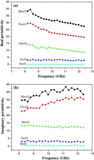
The a real and b imaginary parts of the relative permittivity for the WMCNTs-added styrene acrylic emulsion-based composite in the frequency of 8.2–12.4 GHz
EMI Shielding Efficiency
The EMI SE of a material is defined as the ratio of transmitted and incident electromagnetic power and given by:
where PT and P0 are the transmitted and incident power, respectively. The unit of the EMI SE is decibel (dB).The total EMI shielding is the result of reflection (R), absorption (A) and internal multiple reflection (M) of the incident electromagnetic waves on the samples, i.e.
The electromagnetic radiation penetrates only near surface region of an electrical conductor in high frequencies. The SE depends on the relative value of the thickness of the sample (t) compared to the skin depth, which in meters is defined by:
where f is the frequency of radiation in Hz, μ is the magnetic permeability of the sample, μ = μ0μr, μ0 = 4π × 10−7 Hm−1 is the absolute permeability of free space, since the MWCNTs wall and styrene acrylic polymer are diamagnetic, we have μr = 1. σ is the AC conductivity of the sample in S/m. ɛ0 is the permittivity of the free space, ɛ0 = 8.854 × 10⁻¹² F/m. When t/δ ≥ 1.3, the material is called ‘electrically thick’ and ‘electrically thin’ in the contrary case [28].
In the far field, for ‘electrically thick’ samples, the SE is expressed as follows [29,30]:
For ‘electrically thick’ films, the SE is given by:
The σac is the AC conductivity in S/m and can be obtained through  at a given frequency [29]. Z0 = 120π is the impedance of the free space and ɛ0 is the permittivity of the free space, ɛ0 = 8.854 × 10¹² F/m. The EMI SE of styrene acrylic emulsion-based composites containing different MWCNTs content in X band is presented in Fig. 6. It is shown that the SE of all the composites is sensitive to the MWCNTs content and increases with the increase in purified MWCNTs content. At low mass fractions, the measured EMI SE of the composites is almost independent of frequency. At high mass fractions, the measured EMI SE shows a slight decrease with increasing frequency for the same loading. The average EMI SE of the composites containing 20 wt% MWCNTs is measured to be 25–28 dB in the whole frequency ranges, indicating a possible applications for commercial uses. Figure 7 shows the measured EMI SE values and the estimated ones from the calculated σac of the styrene acrylic emulsion-based composites at 10.2 GHz. The Eqs. 5 and 6 were used to estimate the EMI SE. As we can see, the measured and the calculated results are in good correlation and increases with the increase in purified MWCNTs concentration and σac. These observations can be understood by a simple phenomenological electrical model of parallel resistors and capacitors formed in the nanocomposite, as reported in [31]. In this model, MWCNTs have excellent electrical properties and high aspect ratio, which can be assumed to be an equivalent resistor. The styrene acrylic emulsion-based polymer matrix can be assumed to be a capacitor. The above-mentioned model can be demonstrated by the supercapacitor structure made by incorporating defective CNTs into polypyrrole via an electrochemical method reported by Hughes et al. [32]. They believed that the acquired supercapacitors are mainly ascribed to the presence of porous structures and the micro-bilayer nature of the defective CNT-filled composite films. When the content of the MWCNTs increases, the number of equivalent parallel resistors and capacitors also increases, consequently, both the σac and EMI SE increase.
Figure 6.
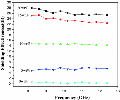
EMI shielding effectiveness for the WMCNTs-added styrene acrylic emulsion-based composite in the frequency range of 8.2–12.4 GHz
Figure 7.
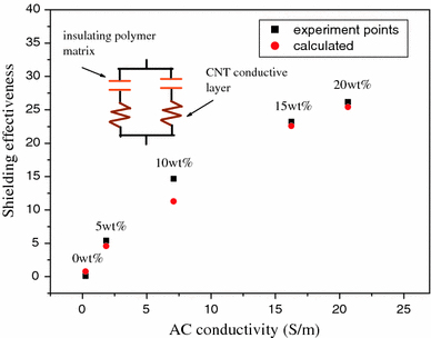
EMI shielding effectiveness as a function of σac for the WMCNTs-added styrene acrylic emulsion-based composite at 10.2 GHz
Conclusion
In summary, we have seen that MWCNTs, with some defects after purification, favor uniform dispersion into an environmentally friendly, water-based styrene acrylic emulsion to form an efficient electromagnetic shielding composite and have a major influence on the dielectric and electromagnetic properties. An EMI shielding effectiveness of ~28 dB in X band was achieved for 20 wt% MWCNTs. The AC conductivity (σac) of the composites, deduced from imaginary permittivity (ɛ′′), was used to estimate the SE and the electromagnetic shielding mechanism was explained by a parallel resistor–capacitor model. We suggest this composite can be applied for building shielding applications in high frequencies.
Acknowledgments
This work is supported by Specialized Research Fund for the Doctoral Program of Higher Education ‖SRFDP) Grant No. 200802481028, Shanghai-Applied Materials Research and Development Fund Grant No. 08520741500, National Natural Science Foundation of China Grant No. 60807008 and National Natural Science Foundation of China Grant No. 50730008.
Open Access
This article is distributed under the terms of the Creative Commons Attribution Noncommercial License which permits any noncommercial use, distribution, and reproduction in any medium, provided the original author(s) and source are credited.
References
- Yang S, Lozano K, Lomeli A, Foltz HD, Jones R. Compos.: Part A. 2005. p. 691. [DOI]
- Li N, Huang Y, Du F, He X, Lin X, Gao H, Ma Y, Li F, Chen Y, Eklund PC. Nano. 2006. p. 1141. COI number [1:CAS:528:DC%2BD28XktFShu7k%3D]; Bibcode number [2006NanoL...6.1141L] [DOI] [PubMed]
- Wang T, Chen G, Wu C, Wu D. Prog. 2007. p. 101. COI number [1:CAS:528:DC%2BD2sXkvF2js7s%3D] [DOI]
- Azim SS, Satheesh A, Ramu KK, Venkatachari G. Prog. 2006. p. 1. COI number [1:CAS:528:DC%2BD28XmtVSl] [DOI]
- Coleman JN, Khan U, Blau WJ, Gun’ko YK. Carbon. 2006. p. 1624. COI number [1:CAS:528:DC%2BD28XkslGkt7w%3D] [DOI]
- Chen CX, Xu D, Kong ES, Zhang YF. IEEE Electron Device Lett. 2006. p. 852. Bibcode number [2006IEDL...27..852C] [DOI]
- Chen CX, Lu Y, Kong ES, Zhang YF, Lee ST. Small. 2008. p. 1313. COI number [1:CAS:528:DC%2BD1cXhtF2gsLnE] [DOI] [PubMed]
- Li Y, Chen CX, Zhang S, Ni Y, Huang J. Appl. 2008. p. 5766. COI number [1:CAS:528:DC%2BD1cXmslWrtbw%3D]; Bibcode number [2008ApSS..254.5766L] [DOI]
- Chen CX, Yang L, Lu Y, Xiao GB, Zhang YF. IEEE Trans. 2009. p. 303. Bibcode number [2009ITNan...8..303C] [DOI]
- Chen CX, Liu L, Lu Y, Kong ES, Zhang YF, Sheng X, Ding H. Carbon. 2007. p. 436. COI number [1:CAS:528:DC%2BD28Xht12gtr3L] [DOI]
- Xiang C, Pan Y, Liu X, Sun X, Shi X, Guo J. Appl. 2005. p. 123103. Bibcode number [2005ApPhL..87l3103X] [DOI]
- Chang CM, Chiu JC, Jou WS, Wu TL, Cheng WH. IEEE J. Sel. Top. Quantum Electron. 2006. p. 1025. COI number [1:CAS:528:DC%2BD28XhtFSjt7jI] [DOI]
- Liu Z, Bai G, Huang Y, Ma Y, Du F, Li F, Guo T, Chen Y. Carbon. 2007. p. 821. COI number [1:CAS:528:DC%2BD2sXhtlWitbw%3D] [DOI]
- Huang Y, Li N, Ma Y, Du F, Li F, He X, Lin X, Gao H, Chen Y. Carbon. 2007. p. 1614. COI number [1:CAS:528:DC%2BD2sXntFKhtL8%3D] [DOI]
- Zhang C-S, Ni Q-Q, Fu S-Y, Kurashiki K. Compos. 2007. p. 2973. COI number [1:CAS:528:DC%2BD2sXpvVajsrY%3D] [DOI]
- Kim HM, Kim K, Lee CY, Joo J, Cho SJ, Yoon HS, Pejaković DA, Yoo JW, Epstein AJ. Appl. 2004. p. 589. COI number [1:CAS:528:DC%2BD2cXmslaqsQ%3D%3D]; Bibcode number [2004ApPhL..84..589K] [DOI]
- Watts PCP, Hsu WK, Barnes A, Chambers B. Adv. 2003. p. 600. COI number [1:CAS:528:DC%2BD3sXjtlyqurs%3D] [DOI]
- Belavin VV, Okoyrub AV, Bulusheva LG. Phys. Solid State. 2002. p. 663. COI number [1:CAS:528:DC%2BD38XjtVGhsbo%3D]; Bibcode number [2002PhSS...44..663B] [DOI]
- Li Y, Chen CX, Pan X, Ni Y, Zhang S, Huang J, Chen D, Zhang YF. Physica B. 2009. p. 1343. COI number [1:CAS:528:DC%2BD1MXksVagsbc%3D]; Bibcode number [2009PhyB..404.1343L] [DOI]
- Chen CX, Zhang YF. J. 2006. p. 172. COI number [1:CAS:528:DC%2BD28Xot1Kntg%3D%3D]; Bibcode number [2006JPhD...39..172C] [DOI]
- Chen CX, Yan LJ, Kong ES, Zhang YF. Nanotechnology. 2006. p. 2192. COI number [1:CAS:528:DC%2BD28Xmtl2nt7k%3D]; Bibcode number [2006Nanot..17.2192C] [DOI]
- Oprea S, Dodita T. Prog. 2001. p. 194. COI number [1:CAS:528:DC%2BD3MXmslGjurc%3D] [DOI]
- Mcnally T, Pötschke P, Halley P, Murphy M, Martin D, Bell SEJ, Brennan GP, Bein D, Lemoine P, Quinn JP. Polymer. 2005. p. 8222. COI number [1:CAS:528:DC%2BD2MXpt1WltLs%3D] [DOI]
- Paton KR, Windle AH. Carbon. 2008. p. 1935. COI number [1:CAS:528:DC%2BD1cXht1Kltr3F] [DOI]
- Kim HM, Choi M-S, Joo J, Cho SJ, Yoon HS. Phys. 2006. p. 054202. Bibcode number [2006PhRvB..74e4202K] [DOI]
- Grunlan JC, Gerberich WW, Francis LF. J. 2001. p. 692. [DOI]
- Grunlan JC, Mehrabi AR, Bannon MV, Bahr JL. Adv. 2004. p. 150. COI number [1:CAS:528:DC%2BD2cXhtlWgu7w%3D] [DOI]
- Morita T, Sumihiro S, Okumura K. IEICE Tech. 2000. p. 19.
- Park SH, Thielemann P, Asbeck P, Bandaru PR. Appl. 2009. p. 243111. Bibcode number [2009ApPhL..94x3111P] [DOI]
- Singh K, Ohlan A, Bakhshi AK, Dhawan SK. Mater. 2010. p. 201. COI number [1:CAS:528:DC%2BD1MXhtlGgtrfP] [DOI]
- Saib A, Bednarz L, Daussin R, Bailly C, Lou X, Thomassin JM, Pagnoulle C, Detrembleur C, Huynen I. IEEE Trans. 2006. p. 2745. COI number [1:CAS:528:DC%2BD28XmvVKmtbk%3D]; Bibcode number [2006ITMTT..54.2745S] [DOI]
- Hughes M, Chen GZ, Shaffer M, Fray DJ, Windle AH. Chem. 2002. p. 1610. COI number [1:CAS:528:DC%2BD38XhtlClsL8%3D] [DOI]


