Abstract
A semiconductor/metal nanocomposite is composed of a porosified silicon wafer and embedded ferromagnetic nanostructures. The obtained hybrid system possesses the electronic properties of silicon together with the magnetic properties of the incorporated ferromagnetic metal. On the one hand, a transition metal is electrochemically deposited from a metal salt solution into the nanostructured silicon skeleton, on the other hand magnetic particles of a few nanometres in size, fabricated in solution, are incorporated by immersion. The electrochemically deposited nanostructures can be tuned in size, shape and their spatial distribution by the process parameters, and thus specimens with desired ferromagnetic properties can be fabricated. Using magnetite nanoparticles for infiltration into porous silicon is of interest not only because of the magnetic properties of the composite material due to the possible modification of the ferromagnetic/superparamagnetic transition but also because of the biocompatibility of the system caused by the low toxicity of both materials. Thus, it is a promising candidate for biomedical applications as drug delivery or biomedical targeting.
Keywords: Porous silicon, Nanocomposite, Magnetic nanoparticles
Introduction
Nanostructuring of materials results in a drastic change of their intrinsic properties. For example, porous silicon achieved by anodization of a silicon wafer offers physical properties, which cannot be observed in case of bulk silicon. Microporous silicon, which exhibits interconnected channels with diameters between 2 and 4 nm, shows a strong luminescence in the visible [1] caused by quantum confinement effects. Macroporous silicon offers properties of a photonic crystal [2]. Moreover, porous silicon possesses the ability to biodegrade within body fluids [3] but is also known as a bioactive material [4], two properties which play opposing roles. Both properties are of interest for medical applications as drug delivery [5] or tissue engineering [6]. Concerning the creation of new materials for scaffolds and bone substitutes, one requirement is the hydroxyapatite growth on the surface by exposing to body fluids, which can also be observed on oxidized porous silicon, which is more stable in simulated body fluids than pure porous silicon [7].
Magnetic nanostructures play a crucial role in ferrofluids [8], high density magnetic data storage [9], catalysis [10] and also biomedical applications [11] as for example drug targeting. The fabrication of magnetic isolated nanoparticles is quite difficult to reach because the particles oxidize easily when using metals due to the large surface area in relation to their volume. Furthermore, they tend to agglomerate because of magnetic interactions. The monodisperse nanoparticles utilized in this work are prepared by high temperature decomposition of an organic precursor in the presence of oleic acid [12-15].
The incorporation of anti-cancer therapeutics, analgetics, proteins and peptides as well as the use of porous silicon as dietary supplement has been taken into consideration. Drug delivery with porous silicon is under discussion in employing particles, films, chip implants and composite materials, whereas microparticles are under great investigation because they are compatible to existing drug delivery concepts [16]. Exploration of porous silicon for utilization in cancer treatment, especially for brachytherapy has been enforced by pSiMedica Inc. [17]. The combination of porous silicon with magnetic particles, namely Fe3O4, and additional loading with a molecular payload is of interest for controlled transport in applying an external magnetic field. The loaded molecules (enzymes) can be transported and subsequently released in an appropriate solution [18]. The fabrication of a porous silicon double-layer of different pore-size is used for loading with magnetite nanoparticles and a small amount of liquid. The samples are heated within an oscillating magnetic field, which is enabled by the superparamagnetic magnetite nanoparticles (~10 nm in size) [19].
In the present work, porous silicon templates with oriented pores grown perpendicular to the sample surface are used to deposit magnetic nanostructures (electrodeposited or immersed) as a three-dimensional arrangement by self-assembly. The combination of a semiconductor with magnetic materials leads to a hybrid system with tailored-specific magnetic properties but is also of interest for possible biomedical applications. The aim of the present work is to give an overview of the versatility of porous silicon and the advantage to combine this semiconductor material with a magnetic metal.
Experiments
The fabrication of porous silicon (PS) is carried out by anodization of an (100) n+ - type silicon wafer (1018 cm −3) in aqueous hydrofluoric acid solution. All porous silicon samples investigated in the frame of this work are anodized in a 10 wt% aqueous HF-solution. The current density has been kept constant at 80 mA/cm 2. Oriented growth and quasi-regular arrangement of the pores is achieved by adjusting the electrochemical parameters, which is described in detail in a previous publication [20]. The pore-growth takes place predominantly along the (100) direction. Small side-pores, which cannot be suppressed in this morphology regime occur in (111) direction. The length of these side-pores does not exceed the pore-radius, which ensures that the main pores are clearly separated from each other. The achieved silicon templates are utilized on the one hand for electrochemical deposition of a ferromagnetic metal and on the other hand to infiltrate nanoparticles. The precipitation of metal nanostructures by pulsed electrodeposition technique is performed in using an adequate metal salt solution [21]. In case of Ni deposition into the pores the electrolyte is composed of 0.2 M NiCl2 and 0.1 M NiSO4, known as Watts electrolyte. The precipitation of the metal nanostructures is carried out with current densities between 15 and 30 mA/cm2. The frequency of the pulses has been chosen between 0.025 and 0.2 Hz.
The metal deposition into porous silicon is a cathodic process reducing the metal salt ions to metal (e.g., Ni2+ + 2e = Ni). The electrodeposition process concerning doped semiconductors is not well understood so far but it can be said that due to higher field strength at the pore tips and concomitant dielectric breakdown of the oxide layer, which covers the pore-walls, starts at the pore bottom.
The geometry and spatial distribution of the metal precipitates within the porous layer can be adjusted by the process parameters (e.g., current density and pulse duration of the current) resulting in samples with tailored magnetic properties. The precipitates can be varied between sphere-like particles of about 60 nm, ellipsoids of a few hundred nanometres (aspect ratio ~10) and needle-like structures reaching a length of a few microns (aspect ratio ~100) by reducing the pulse duration from 40 to 5 s.
Magnetite nanoparticles have been fabricated by high temperature decomposition of iron organic precursors following previously reported works [12,13]. Particles of an average size of 9 nm have been obtained after performing the process steps described by S. Sun [13]. The fabrication has been carried out at the Institute of Material Science at the CSIC in Madrid. These particles, which are quite monodisperse [14] have been mixed with hexane and oleic acid. The resulting magnetic solution has been infiltrated by immersion into the pores of the porous silicon matrices. This immersion process of typically 30 min is performed at room temperature.
The two kinds of semiconductor/metal nanocomposites are characterized by electron microscopy (SEM, TEM) and magnetic measurements performed by SQUID-magnetometry, which complement the investigations to figure out the different behaviour of the two types of specimens (electrochemically deposited ferromagnetic metals, infiltrated magnetite nanoparticles).
Morphological details of the porous silicon template regarding the pore-arrangement, porosity and pore-size as well as of the metal-filled specimens with respect to the geometry and spatial distribution of the precipitated metal nanostructures are gained from the analysis of scanning electron microscopy (SEM) investigations. Figure 1 shows a cross-sectional survey of a typical porous silicon layer exhibiting straight pores grown perpendicular to the wafer surface with an average diameter of 55 nm. A top-view image of the quasi-regular pore-arrangement can be seen in the inset. Analysis of the top-view picture by image processing gives a porosity of about 60%. The precipitated metal nanostructures are investigated in using the back scattered electrons to get element-sensitive information. Furthermore, the nanocomposite is characterized by transmission electron microscopy (TEM), which allows to figure out some interfacial features of the samples.
Figure 1.
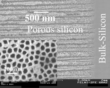
Scanning electron micrograph of the cross-section and the top-view (inset) of a porous silicon sample with a porosity of about 60% achieved by self-organization
Discussion
Investigating the PS/metal interface by TEM one can say that the pore-walls of the PS-matrix are covered by an oxide layer of about 5 nm (Fig. 2). The oxidation of the pores is formed after the anodization by storing in air. FTIR-spectroscopy also shows the presence of oxide in case of aged porous silicon [22]. As-etched porous silicon samples that are hydrogen terminated show three typical absorption peaks around 2,100 cm−1 due to Si–Hx. PS/metal nanocomposite specimens also show an oxygen content, which arises due to oxidation during the deposition process. In Fig. 3, the TEM image shows Ni-particles within the pores. Not all pores of the considered membrane are filled with a Ni-particle because the Ni-structures are deposited randomly within the pores, and one pore is not completely filled between pore tips and surface. Therefore, at a certain level of the porous layer not every pore contains a particle. Furthermore, the preparation technique by focused ion beam (FIB) provokes the loosening of particles. Typically membranes with a thickness of about 50 μm are fabricated. The deposited metal (Ni) structures are also covered by oxide (Fig. 4), which likely arises after the preparation by focused ion beam. On the other side, magnetization measurements of Ni-filled samples do not show an exchange bias effect (not shown here), which means a shift of the hysteesis loop on the abscissa. This result indicates that the Ni-oxide coverage of the nanostructures is not antiferromagnetic.
Figure 2.
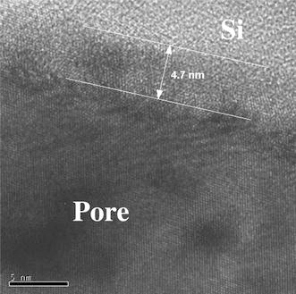
High resolution TEM image of porous silicon, showing an oxide layer of about 5 nm at the pore-walls
Figure 3.
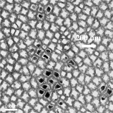
Zero-loss TEM image showing Ni-particles within the pores of the porous silicon matrix. The preparation of the membrane for TEM investigations has been carried out by focused ion beam
Figure 4.
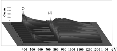
EELS line-scan over an individual embedded Ni-particle. Ni and oxygen have been identified, whereas the oxygen peak at the edges is a combination of both, NiO as well as the oxygen covering the pore-walls of the PS-matrix because the two materials touch
Considering such nanocomposites prepared by electrodeposition of a metal from an adequate metal salt solution, the specific metal precipitation can be influenced by the electrochemical parameters and therefore samples with desired magnetic properties can be achieved. Coercivities, magnetic remanence and magnetic anisotropy strongly depend on the geometry of the precipitated nanostructures as well as on their spatial distribution within the porous layer. Both features can be adjusted mainly by varying the deposition current density and the frequency of the applied current. Considering samples with deposited Ni-particles, coercivities between 500 and 1,000 Oe are obtained in case of easy axis magnetization whereas the magnetic anisotropy between the two magnetization directions, perpendicular and parallel to the sample surface, typically is in the ratio 2:1. Due to the fact that the magnetocrystalline anisotropy of Ni is small, the main contribution stems from the shape of the deposited metal structures. In average, the deposited Ni-structures of the considered sample offer a diameter of about 50 nm and a length of about 150 nm. The magnetic anisotropy of an individual nanowire is dominated by shape anisotropy (1/2 μ0MS ≈ 105 J/m3) [23]. In case of deposited Ni-particles, coupling between the particles is expected due to the large anisotropy between the two magnetization directions. So, it is reasonable that the precipitated Ni-particles dipolarly coupled within one pore leading to a quasi-“magnetic chain” which enhances the anisotropy. The achieved system is of interest because of the adjustable magnetic properties by fabrication parameters but also because of the material combination of silicon compatible with today’s process technology and a ferromagnetic metal.
PS-matrices containing infiltrated magnetite nanoparticles form a composite material are of interest due to the magnetic behaviour but also because of the biodegradability of both materials. This system shows superparamagnetic behaviour at room temperature and ferromagnetism at low temperatures. The transition between the two kinds of magnetism depends on the particle size but also on the interaction between the particles, which means their distance. Thus, the interaction between the nanoparticles can be influenced on the one hand by the thickness of the oleic acid coating and on the other hand by the concentration of the solution of the particles. Figure 5 shows the temperature-dependent magnetization for two different concentrations (ratio 1:2) of the particle solution. For decreasing concentration, the blocking temperature TB is shifted to lower temperatures due to less interaction between the particles as a consequence of their greater distance. In case of superparamagnetic, non-interacting particles of 9 nm in size TB can be estimated around 6 K in using the thermal energy
Figure 5.
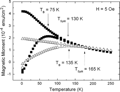
Zero field cooled/field cooled (ZFC/FC) measurements show a shift of the blocking temperature TB to lower temperatures with decreasing concentration, which can be explained by less interaction between the particles.TB indicates the transition between ferro- and superparamagnetic behaviour. The broadening of the peak is not caused by inhomogeneous particle size distribution but by magnetic interactions between the particles. The initial concentration of the particle solution has been diluted with hexane till a 50% solution of the initial one has been reached
being K the anisotropy constant,MS the saturation magnetization,HC the coercive field and V the volume of the individual particles.
In contrast, the experimental gained TB lies at higher temperatures between 75 and 130 K. Furthermore, a broadening of the ZFC-peak with smaller particle distances can be observed. Both are caused by increasing magnetic interactions between the particles in dependence on their average distance.
Conclusions
Porous silicon is a versatile material applicable in many fields of nano-research. In the present work, it is used as template material to embed magnetic nanostructures. On the one hand, ferromagnetic metals are electrochemically deposited within the pores of the matrix leading to a semiconducting/magnetic nanocomposite system. This nanoscopic hybrid material is of interest because of the silicon base material, which makes it applicable in today’s microtechnology and because of the adjustability of its ferromagnetic properties as coercivity, remanence and magnetic anisotropy. The geometry, which can be modified between sphere-like particles and needle-like structures as well as the spatial distribution of the precipitated metal nanostructures within the porous layer is tunable by the electrochemical process parameters resulting in specimens with tailored magnetic properties. On the other hand, Fe3O4 -nanoparticles are infiltrated within the porous layer. The latter system exhibits ferro-/superparamagnetic properties, which can be influenced by varying the nanoparticles in size and their distance, which means by the coating of the particles but also by the concentration of the solution. Due to the low toxicity of magnetite as well as of mesoporous silicon, it is a promising candidate for biomedical applications as drug delivery and drug targeting. All in all porous silicon/metal composites are of great interest in basic research but they are also promising for various magnetic and biomedical applications.
Acknowledgments
This work is supported by the Austrian Science Fund FWF under project P 21155. M. P. Morales and A. G. Roca work was supported by the Ministerio de Ciencia e Innovacion through NAN2004-08805-C04-01 project. The authors would like to thank Prof. H. Krenn from the Institute of Physics at the Karl Franzens University Graz to make available the SQUID-magnetometer and M. Dienstleder from the Institute for Electron Microscopy at the University of Technology Graz for focused ion beam preparation.
References
- Canham LT. Appl. 1990. p. 1046. COI number [1:CAS:528:DyaK3cXmt1ahurc%3D]; Bibcode number [1990ApPhL..57.1046C] [DOI]
- Busch K, Lölkes S, Wehrspohn RB, Föll H. Photonic crystals: advances in design, fabrication ans characterization. Wiley, Berlin; 2004. [Google Scholar]
- Canham L. Adv. 1995. p. 1033. COI number [1:CAS:528:DyaK28XitVWhtA%3D%3D] [DOI]
- Canham LT, Reeves CL, King DO, Branfield PJ, Crabb JG, Ward MCL. Adv. 1996. p. 850. COI number [1:CAS:528:DyaK28XmsFKjsbg%3D] [DOI]
- Canham LT. Nanotechnology. 2007. p. 185704. Bibcode number [2007Nanot..18r5704C] [DOI]
- Sun W, Puzas JE, Sheu T-J, Fauchet PM. Phys. Stat. Sol. (a) 2007. p. 1429. COI number [1:CAS:528:DC%2BD2sXlvFGitLs%3D] [DOI]
- Pastor E, Matveeva E, Parkhutik V, Curiel-Esparza J, Millan MC. Phys. Stat. Sol. (c) 2007. pp. 2136–2140. COI number [1:CAS:528:DC%2BD2sXmtlKgu7g%3D] [DOI]
- Park J, An K, Hwang Y, Park JG, Noh HJ, Kim JY, Park JH, Hwang NM, Hyeon T. Nat. 2004. p. 891. COI number [1:CAS:528:DC%2BD2cXhtVehtrjM]; Bibcode number [2004NatMa...3..891P] [DOI] [PubMed]
- Gill CS, Price BA, Jones CW. J. 2007. p. 145. COI number [1:CAS:528:DC%2BD2sXhtVWjtLzL] [DOI]
- Reiss G, Huetten A. Nat. 2005. p. 725. COI number [1:CAS:528:DC%2BD2MXhtVGgu7%2FJ]; Bibcode number [2005NatMa...4..725R] [DOI] [PubMed]
- Tartaj P, Morales MP, Gonzalez-Carreno T, Veintemillas-Verdaguer S, Serna CJ. J. 2005. p. 28. [DOI] [PubMed]
- Hyeon T, Lee SS, Park J, Chang Y, Na HB. J. 2001. p. 12798. COI number [1:CAS:528:DC%2BD3MXoslSnsrs%3D] [DOI] [PubMed]
- Sun S, Zeng HJ. Am. 2002. p. 8204. COI number [1:CAS:528:DC%2BD38Xks1arurY%3D] [DOI] [PubMed]
- Granitzer P, Rumpf K, Roca AG, Morales MP, Poelt P, Albu M, Mag J, Mat Mag. 2009. (in press) [DOI] [PMC free article] [PubMed]
- Yu WW, Falkner JC, Yavuz CT, Colvin VL. Chem. 2004. p. 2306. [DOI] [PubMed]
- Anglin EJ, Cheng L, Freeman WR, Sailor MJ. Adv. 2008. pp. 1266–1277. COI number [1:CAS:528:DC%2BD1cXosVOnsrs%3D] [DOI] [PMC free article] [PubMed]
- Coffer JL, Whitehead MA, Nagesha DK, Mukherjee P, Akkaraju G, Totolici M, Saffie RS, Canham LT. Phys. Stat. Sol. (a) 2005. pp. 1451–1455. COI number [1:CAS:528:DC%2BD2MXmtVens7w%3D]; Bibcode number [2005PSSAR.202.1451C] [DOI]
- Thomas JC, Pacholski C, Sailor MJ. R. 2006. pp. 782–787. COI number [1:CAS:528:DC%2BD28Xlt12ktbY%3D] [DOI] [PubMed]
- Park JH, Derfus AM, Segal E, Vecchio KS, Bhatia SN, Sailor MJ, Am J. Chem. 2006. pp. 7938–7946. COI number [1:CAS:528:DC%2BD28XkvVehtbY%3D] [DOI] [PMC free article] [PubMed]
- Granitzer P, Rumpf K, Pölt P, Reichmann A, Krenn H. Phys. E. 2007. p. 205. COI number [1:CAS:528:DC%2BD2sXktF2ltLw%3D] [DOI]
- Granitzer P, Rumpf K, Poelt P, Simic S, Krenn H. Phys. Stat. Sol. (a) 2008. p. 1443. COI number [1:CAS:528:DC%2BD1cXot1ejtLc%3D] [DOI]
- Granitzer P, Rumpf K, Poelt P, Albu M, Chernev B. Phys. Stat. Sol. (c) p. 1340. (in press)
- Günther A, Monz S, Tschöpe A, Birringer R, Michels A. J. 2008. p. 1340. Bibcode number [2008JMMM..320.1340G] [DOI]


