Abstract
A new method is presented for rapid and accurate large volumetric radiofrequency (RF) field (B1+) mapping. This method is a modification of the double-angle method (DAM) which accelerates imaging speed and applies 3D acquisition to improve B1+ measurement accuracy. It reduces repetition time and scan time by introducing a catalyzation RF pulse chain at the end of each DAM repetition cycle. The catalyzation pulse chain ensures that, after each TR period, the longitudinal magnetizations reach the same state for both measurements at two flip angles for the DAM so that the long TR requirement (TR ≥ 5T1) for complete relaxation of longitudinal magnetization of DAM becomes unnecessary. A multi-echo imaging sequence is additionally incorporated to further improve the efficiency of data acquisition. Simulations demonstrate an excellent flip angle measurement accuracy for catalyzed DAM even with TR ≪ T1. Phantom and in vivo volunteer studies are presented to demonstrate the catalyzation effect upon B1+ mapping and the application of 3D catalyzed DAM for rapid and accurate large volume RF field mapping.
Keywords: Radiofrequency (RF) field mapping, double-angle method (DAM), multi-echo imaging, quantitative MRI
Introduction
Transmitted radiofrequency (RF) magnetic field (B1+) inhomogeneity has an important influence on MR image quality, and is a substantial source of error for quantitative MRI and MR spectroscopy measurements. Although B1+ field distribution can be estimated by theoretical calculation or phantom measurement, in vivo B1+ field mapping is highly desirable because the electromagnetic field interacts with the subject and thus B1+ field distribution depends upon the transmit coil position, coil loading, dielectric properties of the tissues, and the body shape of the subject (1).
Several B1+ mapping techniques have been developed for in vivo applications. These methods are based on fitting an assumed signal behavior over progressively increasing flip angles (2), calculation of the signal ratio from two flip angles (3-5), stimulated echoes (6,7) or dual RF pulses in steady-state (8), finding the 180° signal null (9), or monitoring signal phase (10,11). Among these methods, the double-angle method (DAM) is generally considered the most simple and straightforward. Two images are acquired at two different nominal flip angles (usually α and 2α). The ratio of these two signal magnitudes is used to derive a B1+ map. To eliminate T1 dependence, this method requires a sufficiently long repetition time (TR ≥ 5T1) to achieve complete relaxation of magnetization (3). To improve time efficiency, modifications to DAM have sought to either reduce TR by compensation (3) or reset saturation (12) pulses, or include fast acquisition sequences with extended echo train lengths (13,14), echo-planar (4,5) or spiral (12) k-space sampling trajectories. However, further improvements to DAM time efficiency, anatomical coverage, and accuracy continue to be necessary.
Due to time constraints and relatively long TR (TR ≥ 5T1) requirements, currently DAM is used exclusively in 2D imaging. To increase spatial coverage within the same scan time, a 2D multi-slice acquisition is often used to read multiple slices in every repetition cycle. However, particularly for these 2D acquisition approaches, problems can arise from non-uniform excitation RF slice profiles (8). The excitation RF slice profile greatly influences the flip angle calibration and may cause a significant deviation in B1+ measurement (15). One method to correct the non-uniform RF slice-profile is to compute excitation flip angle profiles based on the RF pulse shape, bandwidth, duration, and nominal flip angle for a particular sequence (16). However, this approach in 2D cannot differentiate the excited slice side lobe from the main lobe which complicates the calibration of a specific slice region. Additionally, the 2D acquisition may be sensitive to in-flow effects, and these flow artifacts may introduce additional inaccuracy in flip angle measurements. A volumetric 3D acquisition technique that inherently produces better defined slice profiles should mitigate the excitation profile and flow artifact problems during B1+ mapping. With a 3D acquisition, slice profile can be calibrated in a number of different partitions, and the slice side lobes and transition regions where flip angle falls off towards the edge of the slice can easily be excluded using slice oversampling.
In this study, a modified DAM is proposed to enable rapid 3D flip angle imaging. In order to quickly eliminate T1 dependence in DAM calculation, an RF pulse chain (catalyzation chain) is added at the end of each DAM repetition cycle. The catalyzation pulse chain ensures that, after each TR period, the longitudinal magnetizations reach the same state for both measurements at two flip angles for the DAM thereby enabling a shorter TR for fast imaging while avoiding T1 bias. A multi-echo sequence (13,17) was incorporated to further improve imaging efficiency. Phantom and in vivo volunteer studies are presented to demonstrate the catalyzation effect upon B1+ mapping and the application of multi-echo catalyzed DAM for rapid and accurate 3D RF field mapping.
Experimental
Theory
For a gradient-echo (GRE) or spin-echo (SE) sequence or a turbo spin-echo (TSE) sequence with excitation angle α, the signal intensity can be written as follows (3)
| [1] |
where Cr(r) is the receiver coil sensitivity profile, ρ0(r) is proton density, Ct(r) is the flip angle calibration factor, TR is the repetition time, TE is the echo time, T1(r) is the tissue T1, T2(r) is the tissue T2, and f(Ct(r)α, TR, TE, T1(r)) is a term describing the longitudinal relaxation.
For DAM, two images are acquired at two different excitation flip angles: α1 and α2, with all other parameters kept the same. The ratio of the two images is
| [2] |
If the ratio of longitudinal magnetizations following two different flip angle α1 and α2 excitations approaches unity, i.e.
| [3] |
Then Eq. [2] can be simplified to
| [4] |
With α2 = 2α1,
| [5] |
The spatial distribution of the flip angle Ct(r)α1 gives an indirect measure of the B1+ field. With nominal flip angle value α1, Eq. [5] can be used to derive the flip angle calibration factor Ct(r).
From the analysis above, we can see that the satisfaction of Eq. [3] is a key step for T1 dependence to be removed from the SI1(r) / SI2(r) ratio and subsequent flip angle calculation. With traditional DAM, in order to satisfy Eq. [3], a long repetition time (TR ≥ 5T1) is typically required to achieve full relaxation of longitudinal magnetization. In the proposed catalyzed DAM, a catalyzation RF pulse chain with transverse spoilers is introduced at the end of each repetition cycle during a DAM B1+ measurement, as illustrated in Figure 1. The catalyzation RF pulse chain is composed of a compensation pulse (δi) (with δ1 = α2 and δ2 = α1) (3) and several catalyzation chain pulses (θ). The ratio of corresponding longitudinal magnetizations from two measurements at flip angle α1 and α2 will be catalyzed to unity by the catalyzation pulse chain. Hence, the requirements of Eq. [3] are satisfied permitting shorter TR without T1 dependence within SI1(r) / SI2(r) measurements.
Figure 1.
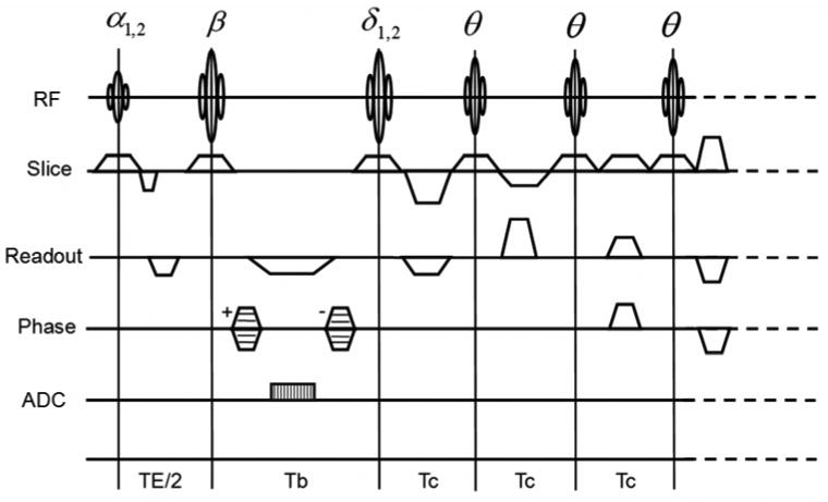
Schematic diagram of catalyzed DAM SE sequence. α1,2: excitation pulse pair. δ1,2: compensation pulse pair. β: refocusing pulse. θ: catalyzation chain pulse. Tb: refocusing and compensation pulses spacing. Tc: catalyzation chain pulse spacing. Variant spoiling gradients in sign and amplitude are present in slice, readout and phase directions.
The signal behavior and flip angle measurement accuracy of catalyzed DAM were predicted by numerical simulations based on the Bloch equation. Signal intensities for two different DAM excitation schemes, SI1 and SI2, were calculated, and the ratio was used to estimate the flip angle according to Eq. [5]. The accuracy of flip angle calculation using Eq. [5] relies strongly upon the satisfaction of Eq. [3]. The catalyzation effect is depicted in Figure 2, which demonstrates the accuracy of flip angle measurements for different TR/T1 ratios and various catalyzation schemes. Both the length of the catalyzation pulse chain and the flip angle of chain pulses can have a significant impact upon catalyzation effect. As the number of catalyzation chain pulses increases, the catalyzation effect enhances. As the flip angle of the catalyzation chain pulses gets closer to 90°, fewer chain pulses or shorter TR time is necessary to achieve the same level of accuracy. However, even with 45° flip angle, at TR = 0.3×T1, three catalyzation chain pulses are sufficient for 99.5% accuracy. The simulated accuracy of flip angle measurements for different flip angle calibration factors Ct with various spoiling and off-resonance conditions are shown in Figure 3. The spoiling of transverse magnetization between catalyzation RF pulses is critical. Perfect to excellent transverse spoiling (e.g. spoiling > 99% transverse magnetization) ensures a strong catalyzation effect with a small number of catalyzation chain pulses, which is tolerant to off-resonance effects, across a wide angular range (0.2 < Ct < 1.5, over 98% accuracy) (Fig. 3a-f). However, deficient transverse spoiling (e.g. spoiling ≤ 90% transverse magnetization) causes a degraded catalyzation effect with a small number of catalyzation chain pulses, which becomes sensitive to the off-resonance effects, (Fig. 3g-i). Additionally, the spoiling of transverse magnetization is especially crucial for small Ct (Ct < 0.5) because minute deviations in signal intensities can introduce magnified percentage error when a small flip angle is calculated from Eq. [5]. In spite of this potential complication, for applications with transmitter coils affording good RF uniformity, where the flip angle calibration factor is likely to vary within 0.6 < Ct < 1.5 (7,9), a high percentage accuracy can easily be achieved with only a small number of catalyzation chain pulses.
Figure 2.
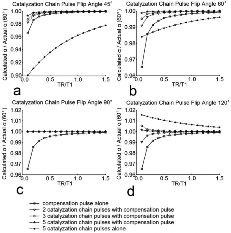
Simulation of flip angle measurement accuracy for different catalyzation schemes with dependence upon TR/T1 ratio. The simulation parameters include: T1 =1000 ms, T2 = 50 ms, TR cycles = 10, excitation flip angle pair: α1 = 60°, α2 = 120°, refocusing flip angle: β = 180°, compensation pulse flip angle pair: δ1 = 120°, δ2 = 60°, catalyzation chain pulse flip angle: a) θ = 45 °, b) θ = 60 °, c) θ = 90 °, d) θ = 120 °, TE = 10 ms, Tb = 10 ms, Tc = 5 ms, Ct = 1, Actual α = 60°.
Figure 3.
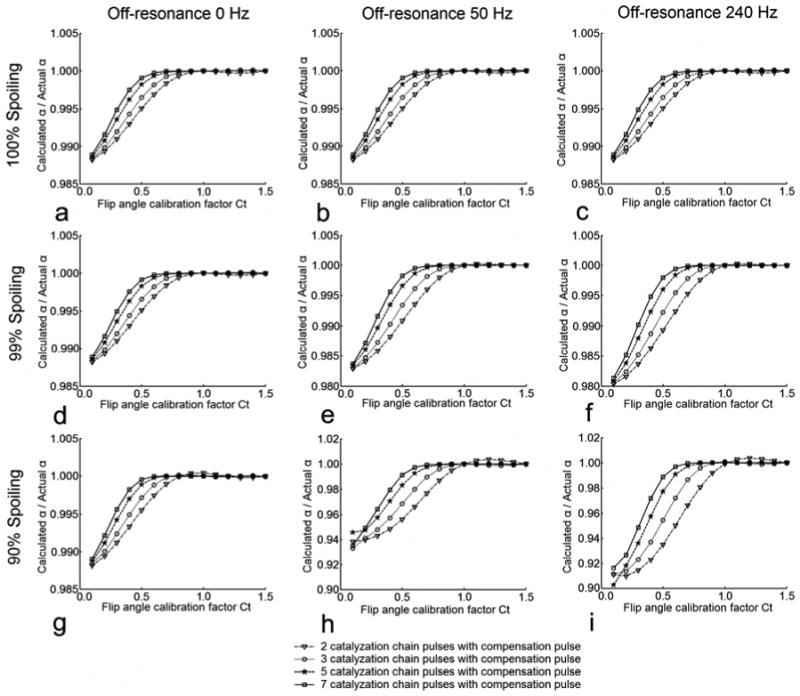
Simulation of flip angle measurement accuracy for different spoiling and off-resonance conditions with dependence upon flip angle calibration factor Ct. The simulation parameters include: T1 =1000 ms, T2 = 50 ms, TR cycles = 10, nominal excitation flip angle pair: α1norm = 60°, α2norm = 120°, refocusing flip angle: β = 180°, nominal compensation pulse flip angle pair: δ1norm = 120°, δ2norm = 60°, nominal catalyzation chain pulse flip angle: θnorm = 90 °, TE = 10 ms, Tb = 10 ms, Tc = 5 ms, Actual α = Ct × 60°, actual compensation pulse flip angle δ1,2actual = Ct × δ1,2norm, actual catalyzation chain pulse flip angle θactual = Ct × θnorm.
Spoiling scheme design
As shown in Fig. 3, spoiling of transverse magnetization is imperative for the catalyzation process. Two common methods were incorporated for spoiling. First, spoiling gradients alternating in polarity and varying in gradient moment (18), were used for each catalyzation pulse along all three axes as illustrated in Fig. 1. The spoiling moments of these gradients in all three directions after each RF pulse were set to generate a phase distribution of at least 36π within one voxel. Second, a phase-cycled RF spoiling scheme was applied consecutively to each catalyzation chain pulse (19). In order to use a very short TR which is less than 5 times T2, variant gradient spoiling strategies were set in different TRs to avoid generating stimulated echos. When a multi-echo sequence was used for imaging, alternating and varying crusher gradient methods were also applied to preserve only the primary echo pathway and eliminate stimulated echos (18).
Experimental studies
All experiments were performed using a 3.0 Tesla MAGNETOM Trio clinical MRI scanner (Siemens AG Healthcare Sector, Erlangen, Germany). The Trio scanner had a horizontal bore with 60 cm inner diameter. The Trio gradient system offered a maximun amplitude of 40 mT/m in each axis and a maximun slew rate of 200 T/m/s. Slab-selective RF pulses were used in the 3D catalyzed DAM experiments. Excitation and refocusing pulses were Siemens-equipped RF pulses for SE/TSE sequence. The 90° catalyzation chain pulse was a maximum-phase Shinnar-Le Roux (SLR) pulse (20) with a nominal bandwidth time product of 6 and a duration of 2.56 ms. 3D slice over-sampling was applied to prevent outside signal from wrapping into the imaging slices. 3D catalyzed DAM was first validated in a phantom and then tested in a healthy volunteer. The body coil was used as RF transmitter and a receiver-only two-channel head coil was used for signal reception. In order to further accelerate acquisition speed, a TSE sequence was used for all experiments (13). The slice encoding direction was cranial-caudal for both the phantom and volunteer studies. The frequency encoding direction was left-right for the phantom study and anterior-posterior for the volunteer study. Defined in the pulse sequence diagram shown in Figure 1, common imaging parameters applied in the phantom and volunteer studies were: TE/Tb/Tc = 12/12/12 ms, excitation/compensation (α/δ) flip angle = 60°/120° and 120°/60°, refocusing (β) flip angle = 180°, catalyzation chain pulse (θ) flip angle = 90°, 3 catalyzation chain pulses, 6/8 partial Fourier in the slice encoding direction, 660 Hz/pixel bandwidth (BW), echo train length (ETL) = 3.
A phantom study was designed to validate the accuracy of catalyzed DAM by comparing it with traditional DAM and compensated DAM (3). The phantom was a bottle of fat free milk (Jewel) with T1 of 1830 ms (measured using an inversion-recovery method). 3D TSE traditional, compensated, and catalyzed DAM acquisitions were performed with TR = 2000, 1000, 500, 250 and 135 ms. 3D TSE DAM with a long TR of 15000 ms was also performed to provide a reference standard of measurement. Other imaging parameters included: 320×180×40 mm3 FOV, 128×72×8 matrix, 2.5×2.5×5 mm3 voxel size, 100% slice oversampling. The measured flip angles from traditional, compensated and catalyzed DAM at different TR were compared to a reference flip angle value obtained from DAM with TR = 15000 ms. The percentage root-mean-squared error (RMSE) was calculated within the central region of the phantom flip angle map.
The accuracy of 3D TSE catalyzed DAM was validated in vivo in the brain of a 27-year old male healthy volunteer. Our study protocol was approved by our Institutional Review Board and written informed consent was obtained from the volunteer. 3D TSE traditional, compensated, and catalyzed DAM acquisions were performed with the following parameters: TR = 1000 ms and 175 ms, 360×180×40 mm3 FOV, 128×64×8 matrix, 2.8×2.8×5 mm3 voxel size, 100% slice oversampling. 3D TSE catalyzed DAM with a TR of 3000 ms was also performed to provide measurement reference. The scan time was 46 sec with a 175-ms TR and 13 min and 8 sec with a 3000-ms TR. The measured flip angles from traditional, compensated and catalyzed DAM at different TR were compared to a reference flip angle value obtained from catalyzed DAM with TR = 3000 ms, by calculating percentage root-mean-squared (RMS) difference within the central region of the brain flip angle maps.
A 3D large volume flip angle map of the brain was acquired in the same volunteer using catalyzed DAM with the following parameters: TR = 175 ms, 360×180×144 mm3 FOV, 128×64×48 matrix, 2.8×2.8×3 mm3 voxel size, 50% slice oversampling. The total scan time was 3 min 28 sec.
Results
Fig. 4a-d shows the reference flip angle map of the phantom from DAM with TR = 15000 ms (Fig. 4a), and corresponding flip angle map from catalyzed DAM with TR = 135 ms (Fig. 4b), compensated DAM with TR = 135 ms (Fig. 4c), and traditional DAM with TR = 2000 ms (Fig. 4d). While both traditional DAM with TR = 2000 ms and compensated DAM with TR = 135 ms consistently underestimated the flip angle values, catalyzed DAM with TR = 135 ms closely approximated reference flip angles calculated using the long TR method. This flip angle distribution was a result of the dielectric resonance (7,9). Flip angle profiles from traditional, compensated and catalyzed DAM with different TRs through the center line of the phantom are compared in Fig. 4e. Even using a TR = 2000 ms (which is roughly proportional to the 1830 ms T1 value of the phantom), traditional DAM is clearly discrepant from the reference method. Compensated DAM provided an improvement over traditional DAM clearly suppressing T1 effects for B1+ measurement; compensated DAM using TR ≥ 500 ms provided similar measurement results as the reference long TR method. However, compensated DAM at short TRs (< 500 ms) systematically underestimated the flip angle value when compared to the reference method. In contrast, catalyzed DAM at all TRs showed excellent agreement with the reference method. Table 1 contains the RMSE of traditional, compensated and catalyzed DAM with different TRs. While compensated DAM showed a great improvement in accuracy compared to traditional DAM, its RMSE increased to 4.2% when TR decreased to 135 ms. In contrast, catalyzed DAM demonstrated high accuracy at all TRs, and the RMSE of catalyzed DAM was only 0.9% even for TR = 135 ms (< 1/13 T1).
Figure 4.
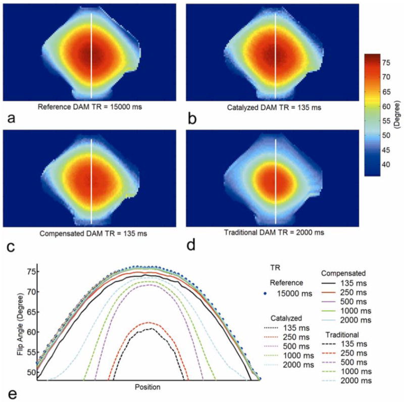
Validation study in a phantom. The phantom was a bottle of fat free milk with T1 of 1830 ms. a) Reference flip angle map of the phantom from DAM with TR = 15000 ms, and corresponding flip angle maps from b) catalyzed DAM with TR = 135 ms, c) compensated DAM with TR = 135 ms, and d) traditional DAM with TR = 2000 ms. e) Phantom flip angle profiles from traditional (dashed line), compensated (solid line), and catalyzed (dotted line) DAM with different TR.
Table 1.
RMSE of Flip Angle Measurement Compared to DAM with TR = 15000 ms
| TR | Traditional DAM | Compensated DAM | Catalyzed DAM |
|---|---|---|---|
| 135 ms | 60.1% | 4.2% | 0.9% |
| 250 ms | 55.3% | 1.9% | 0.6% |
| 500 ms | 35.0% | 1.4% | 0.3% |
| 1000 ms | 23.0% | 1.0% | 0.4% |
| 2000 ms | 13.1% | 0.7% | 0.3% |
Fig. 5 shows the flip angle maps of the phantom at different partitions throughout the 3D volume from reference DAM with TR = 15000 ms and catalyzed DAM with TR = 135 ms. These flip angle maps demonstrated relatively high B1+ value in the middle of the 3D slab and a decrease in B1+ strength toward the edge. This result is consistent with previous experimental measurements (7, 9). Catalyzed DAM measurements with TR = 135 ms were well correlated to the reference measurements at all partition locations across the 3D volume.
Figure 5.
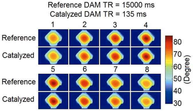
Flip angle maps of the phantom at different partitions throughout the 3D volume from DAM with TR = 15000 ms and catalyzed DAM with TR = 135 ms. These maps were displayed in ascending position order. (1: the lowest position, 4 and 5: the two central partitions, 8: the highest position)
Fig. 6a-d shows the in vivo flip angle maps of human brain from catalyzed DAM with TR = 3000 ms (Fig. 6a) and 175 ms (Fig. 6b), compensated DAM with TR = 175 ms (Fig. 6c), and traditional DAM with TR = 1000 ms (Fig. 6d). The flip angle maps from both catalyzed DAMs depicted a smooth spatial pattern across the head. The flip angle values increased towards the center of the head due to dielectric resonance (9,12), similar to the phantom flip angle map shown in Fig. 4a. The flip angle map from traditional DAM with TR =1000 ms demonstrated residual T1 dependence, as 1000 ms is roughly the T1 value of white matter, but much less than the T1 values of gray matter and cerebrospinal fluid at 3.0 T (21). While both traditional DAM with TR =1000 ms and compensated DAM with TR = 175 ms consistently underestimated the flip angle values, catalyzed DAM with TR = 175 ms closely agreed with the measurement obtained using the reference method (catalyzed DAM with TR = 3000 ms). Flip angle profiles from traditional, compensated and catalyzed DAM with different TRs through the center line of the brain are compared in Fig. 6e. Table 2 contains the RMS difference of traditional, compensated and catalyzed DAM with different TRs compared to catalyzed DAM with TR = 3000 ms. These in vivo measurements gave similar results to the phantom study. Traditional DAM using TR = 1000 ms clearly deviated from the reference method in calculated flip angle profile, with RMS difference > 12%. Compensated DAM provided an improvement over traditional DAM; compensated DAM using TR = 1000 ms provided excellent agreement with the reference method (RMS difference = 0.6%). However, with TR = 175 ms, compensated DAM systematically underestimated the flip angle value, producing a 4.0% RMS difference from the reference. In contrast, catalyzed DAM at all TRs showed excellent agreement with the reference method (RMS difference = 0.6% for TR = 1000 ms and 0.9% for TR = 175 ms).
Figure 6.
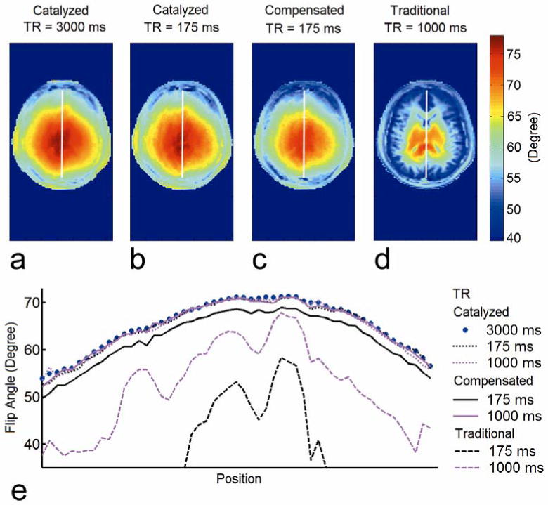
In vivo validation study in a volunteer brain. a) Flip angle map of the brain from catalyzed DAM with TR = 3000 ms, and corresponding flip angle maps from b) catalyzed DAM with TR = 175 ms, c) compensated DAM with TR = 175 ms, and d) traditional DAM with TR = 1000 ms. e) Phantom flip angle profiles from traditional (dashed line), compensated (solid line), and catalyzed (dotted line) DAM with TR = 1000 ms and 175 ms.
Table 2.
RMS Difference of Flip Angle Measurement Compared to Catalyzed DAM with TR = 3000 ms
| TR | Traditional DAM | Compensated DAM | Catalyzed DAM |
|---|---|---|---|
| 175 ms | 33.6% | 4.0% | 0.9% |
| 1000 ms | 12.2% | 0.6% | 0.6% |
Fig. 7 shows in vivo three orthogonal projection TSE images through a large volume of the brain (Fig. 7a-c) and corresponding calculated flip angle maps (Fig. 7d-f). All three flip angle maps showed a relatively low spatial variation over the brain, and an increase in RF field strength toward the center of the head.
Figure 7.
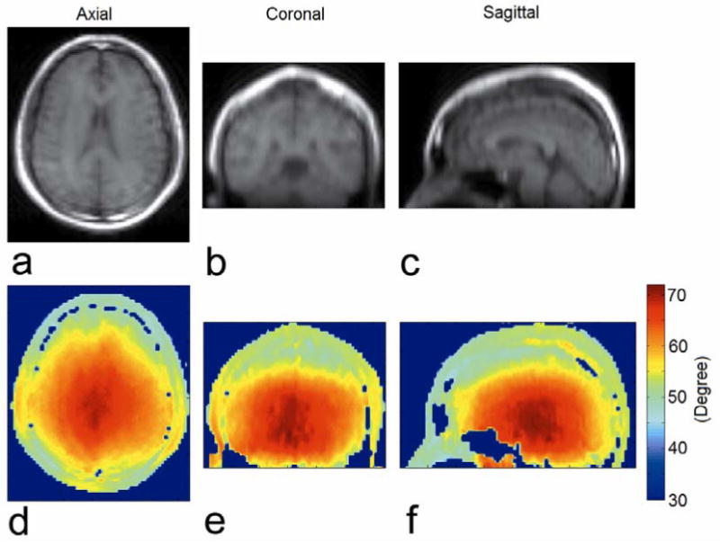
In vivo (a) axial (b) coronal (c) sagittal TSE images (α = 60°) of a volunteer brain and (d-f) the corresponding calculated flip angle maps from catalyzed DAM with TR = 175 ms.
Discussion and Conclusion
The presented 3D catalyzed double-angle method was designed for rapid and accurate volumetric RF field mapping and was validated in phantom and in vivo volunteer studies. This 3D B1+ mapping technique utilizes 3D slab-selective excitation and 3D slice over-sampling to improve the excitation slice profile which is a well-documented concern for the accuracy of 2D B1+ mapping (4,8,9,15). Although 3D slice over-sampling increases imaging time, it ensures superior computational accuracy by isolating the signals from the transition region. Smaller slice over-sampling could be investigated to save scan time at the expense of B1+ mapping accuracy. Another benefit provided by 3D acquisition is the intrinsic high SNR compared to 2D acquisition with the same resolution. This SNR advantage should permit the use of shorter TRs (i.e. < 200 ms) while maintaining flip angle measurement accuracy.
Catalyzed DAM can reduce DAM reliance upon long TR (TR > 5T1) for the removal of signal T1 dependency. Robust magnetization catalyzation is a key. Catalyzation represents a comprehensive approach that quickly forces the ratio of longitudinal magnetizations of two measurements at flip angle α1 and α2 of DAM toward unity. The catalyzed method is not limited to 3D acquisition and can be applied in 2D as well. Furthermore, the catalyzed method can use conventional slice-selective or slab-selective RF pulses, and does not demand B1+ and B0 insensitive pulses as required for the reset saturation method (12). Although RF pulses that are insensitive to B1+ variations and off-resonance can be helpful for catalyzation, there are concerns about specific absorption rate (SAR) at high field strength when a short TR is used. The effectiveness of catalyzation was demonstrated in simulations by varying the TR/T1 ratio and flip angle calibration factor Ct, and in experiments by varying the TR. From numerical simulations and experiments, it is noteworthy that the compensation pulses alone create considerable catalyzation effect. However, the combination of catalyzation chain pulses and compensation pulses can produce much more efficient and effective catalyzation effect than catalyzation chain pulses or compensation pulses applied independently. This advancement in catalyzation effect provides a further reduction in acquisition time, as catalyzed DAM uses shorter TR than compensated DAM to reach comparable high accuracy. Based on simulation and experiments, the typical number of catalyzation chain pulses was chosen to be 3-5. To maximize the catalyzation effect, catalyzation chain pulses should use a 90° flip angle. When a small flip angle (e.g. < 30°) is used for a small number of catalyzation chain pulses, failure of catalyzation may occur. Increasing the number of catalyzation chain pulses can strengthen the catalyzation effect, however, at the price of increased RF deposition and prolonged minimum TR. Successful spoiling of transverse magnetization between catalyzation RF pulses is also of great importance for the catalyzation process and ensures relative immunity of catalyzed DAM to off-resonance effects. Being validated in the experiments, catalyzed DAM with TR < 1/13 T1 can achieve a similar accuracy in flip angle measurement as DAM with TR > 5 T1. However, there is still a trade-off between the choices of TR and the accuracy of catalyzed DAM, because a longer TR a) allows greater longitudinal magnetization recovery and resultant high SNR which will improve the accuracy of B1+ quantification, and b) mitigates the potential angular distortion associated with small flip angle computations (resulting from imperfect longitudinal magnetization catalyzation and the nonlinearity of DAM (Eq. [5])).
While 3D catalyzed DAM was demonstrated using a TSE sequence, this technique can use either a GRE, SE or TSE sequences. SE and TSE sequences provide superior image quality to GRE sequences when susceptibility and chemical shift effects are present. Although only ETL = 3 was used in our study for imaging speed acceleration, higher ETL number can be applied (13) as long as the stimulated echoes can be suppressed and SAR is controlled within safety limits. Another advantage of this proposed 3D catalyzed DAM is that it does not require a fast steady-state like FLASH sequence, and as such is compatible with other fast readout methods such as EPI and spiral. These fast readout methods could be applied to further shorten scan time without changing TR.
There are several limitations associated with the proposed method. Additional catalyzation chain pulses increase SAR, especially when a large number of pulses at high flip angle are used. SAR limits constrain the minimum usable TR and might limit the application of the proposed method at high field strength. However, this concern was able to be controlled within the safety limit for each of our experiments at 3.0 T. At higher field strength than 3.0 T, a less SAR bearing sequence such as SE, GRE, EPI or a multi-echo sequence with low refocusing flip angle (17) could be used to replace the TSE sequence for acquisition. Another problem is that slab-selective 3D catalyzed DAM may suffer from motion artifacts and blood flow. Shortened total scan time and a modification of current catalyzed DAM sequence to be an interleaved acquisition for double angles could help alleviate bulk motion artifacts and image co-registration issues. While slab-selective volumetric 3D approaches already offer superior suppression of in-flow effects than 2D approaches, flow saturation bands can be applied to further reduce flow artifacts at the expense of increasing SAR. Just as with traditional DAM, the presented method warrants critique due to the implicit assumption that the actual flip angle scales linearly with prescribed nominal flip angle. However, previous publications have shown that this linearity can be preserved even with very high-flip-angles upwards of 240° (9,22).
In conclusion, 3D catalyzed DAM provides a rapid and accurate method for large volumetric RF field mapping. Potential applications of the proposed 3D B1+ mapping technique are the corrections of RF inhomogeneity in quantitative applications, such as T1 mapping using variable flip angles method (21,22), T2 mapping using multiple-echo imaging (13,18), magnetization transfer ratio (MTR) measurements (14), and dynamic contrast enhanced (DCE) MRI quantification of pharmacokinetic parameters (23,24).
References
- 1.Hoult DI, Phil D. Sensitivity and power deposition in a high-field imaging experiment. J Magn Reson Imaging. 2000;12(1):46–67. doi: 10.1002/1522-2586(200007)12:1<46::aid-jmri6>3.0.co;2-d. [DOI] [PubMed] [Google Scholar]
- 2.Hornak JP, Szumowski J, Bryant RG. Magnetic field mapping. Magn Reson Med. 1988;6(2):158–163. doi: 10.1002/mrm.1910060204. [DOI] [PubMed] [Google Scholar]
- 3.Stollberger R, Wach P. Imaging of the active B1 field in vivo. Magn Reson Med. 1996;35(2):246–251. doi: 10.1002/mrm.1910350217. [DOI] [PubMed] [Google Scholar]
- 4.Wang J, Qiu M, Constable RT. In vivo method for correcting transmit/receive nonuniformities with phased array coils. Magn Reson Med. 2005;53(3):666–674. doi: 10.1002/mrm.20377. [DOI] [PubMed] [Google Scholar]
- 5.Wang J, Qiu M, Yang QX, Smith MB, Constable RT. Measurement and correction of transmitter and receiver induced nonuniformities in vivo. Magn Reson Med. 2005;53(2):408–417. doi: 10.1002/mrm.20354. [DOI] [PubMed] [Google Scholar]
- 6.Akoka S, Franconi F, Seguin F, Le Pape A. Radiofrequency map of an NMR coil by imaging. Magnetic resonance imaging. 1993;11(3):437–441. doi: 10.1016/0730-725x(93)90078-r. [DOI] [PubMed] [Google Scholar]
- 7.Jiru F, Klose U. Fast 3D radiofrequency field mapping using echo-planar imaging. Magn Reson Med. 2006;56(6):1375–1379. doi: 10.1002/mrm.21083. [DOI] [PubMed] [Google Scholar]
- 8.Yarnykh VL. Actual flip-angle imaging in the pulsed steady state: a method for rapid three-dimensional mapping of the transmitted radiofrequency field. Magn Reson Med. 2007;57(1):192–200. doi: 10.1002/mrm.21120. [DOI] [PubMed] [Google Scholar]
- 9.Dowell NG, Tofts PS. Fast, accurate, and precise mapping of the RF field in vivo using the 180 degrees signal null. Magn Reson Med. 2007;58(3):622–630. doi: 10.1002/mrm.21368. [DOI] [PubMed] [Google Scholar]
- 10.Mugler JP, Miller G. Rapid 3D Mapping of the B1 Field Using a Low-Flip-Angle, Phase-Based Method with Improved Sensitivity. Berlin, Germany: 2007. p. 351. [Google Scholar]
- 11.Morrell GR. A phase-sensitive method of flip angle mapping. Magn Reson Med. 2008;60(4):889–894. doi: 10.1002/mrm.21729. [DOI] [PubMed] [Google Scholar]
- 12.Cunningham CH, Pauly JM, Nayak KS. Saturated double-angle method for rapid B1+ mapping. Magn Reson Med. 2006;55(6):1326–1333. doi: 10.1002/mrm.20896. [DOI] [PubMed] [Google Scholar]
- 13.Sled JG, Pike GB. Correction for B1 and B0 variations in quantitative T2 measurements using MRI. Magn Reson Med. 2000;43(4):589–593. doi: 10.1002/(sici)1522-2594(200004)43:4<589::aid-mrm14>3.0.co;2-2. [DOI] [PubMed] [Google Scholar]
- 14.Samson RS, Wheeler-Kingshott CA, Symms MR, Tozer DJ, Tofts PS. A simple correction for B1 field errors in magnetization transfer ratio measurements. Magnetic resonance imaging. 2006;24(3):255–263. doi: 10.1016/j.mri.2005.10.025. [DOI] [PubMed] [Google Scholar]
- 15.Wang J, Mao W, Qiu M, Smith MB, Constable RT. Factors influencing flip angle mapping in MRI: RF pulse shape, slice-select gradients, off-resonance excitation, and B0 inhomogeneities. Magn Reson Med. 2006;56(2):463–468. doi: 10.1002/mrm.20947. [DOI] [PubMed] [Google Scholar]
- 16.Parker GJ, Barker GJ, Tofts PS. Accurate multislice gradient echo T(1) measurement in the presence of non-ideal RF pulse shape and RF field nonuniformity. Magn Reson Med. 2001;45(5):838–845. doi: 10.1002/mrm.1112. [DOI] [PubMed] [Google Scholar]
- 17.Hennig J. Multiecho Imaging Sequences with Low Refocusing Flip Angles. Journal of Magnetic Resonance. 1988;78(3):397–407. [Google Scholar]
- 18.Crawley AP, Henkelman RM. Errors in T2 Estimation Using Multislice Multiple-Echo Imaging. Magnetic Resonance in Medicine. 1987;4(1):34–47. doi: 10.1002/mrm.1910040105. [DOI] [PubMed] [Google Scholar]
- 19.Leupold J, Hennig J, Scheffler K. Moment and direction of the spoiler gradient for effective artifact suppression in RF-spoiled gradient echo imaging. Magn Reson Med. 2008;60(1):119–127. doi: 10.1002/mrm.21614. [DOI] [PubMed] [Google Scholar]
- 20.Pauly J, Le Roux P, Nishimura D, Macovski A. Parameter relations for the Shinnar-Le Roux selective excitation pulse design algorithm [NMR imaging] IEEE transactions on medical imaging. 1991;10(1):53–65. doi: 10.1109/42.75611. [DOI] [PubMed] [Google Scholar]
- 21.Cheng HL, Wright GA. Rapid high-resolution T(1) mapping by variable flip angles: accurate and precise measurements in the presence of radiofrequency field inhomogeneity. Magn Reson Med. 2006;55(3):566–574. doi: 10.1002/mrm.20791. [DOI] [PubMed] [Google Scholar]
- 22.Wang JH, Qiu ML, Kim H, Constable RT. T-1 measurements incorporating flip angle calibration and correction in vivo. Journal of Magnetic Resonance. 2006;182(2):283–292. doi: 10.1016/j.jmr.2006.07.005. [DOI] [PubMed] [Google Scholar]
- 23.Cheng HL. T1 measurement of flowing blood and arterial input function determination for quantitative 3D T1-weighted DCE-MRI. J Magn Reson Imaging. 2007;25(5):1073–1078. doi: 10.1002/jmri.20898. [DOI] [PubMed] [Google Scholar]
- 24.Wang D, Virmani S, Tang R, Szolc-Kowalska B, Woloschak G, Omary RA, Larson AC. Four-dimensional transcatheter intraarterial perfusion (TRIP)-MRI for monitoring liver tumor embolization in VX2 rabbits. Magn Reson Med. 2008;60(4):970–975. doi: 10.1002/mrm.21678. [DOI] [PMC free article] [PubMed] [Google Scholar]


