Abstract
Objective
The purpose of this study was to analyze the biomechanical effects of three different constrained types of an artificial disc on the implanted and adjacent segments in the lumbar spine using a finite element model (FEM).
Methods
The created intact model was validated by comparing the flexion-extension response without pre-load with the corresponding results obtained from the published experimental studies. The validated intact lumbar model was tested after implantation of three artificial discs at L4-5. Each implanted model was subjected to a combination of 400 N follower load and 5 Nm of flexion/extension moments. ABAQUS™ version 6.5 (ABAQUS Inc., Providence, RI, USA) and FEMAP version 8.20 (Electronic Data Systems Corp., Plano, TX, USA) were used for meshing and analysis of geometry of the intact and implanted models.
Results
Under the flexion load, the intersegmental rotation angles of all the implanted models were similar to that of the intact model, but under the extension load, the values were greater than that of the intact model. The facet contact loads of three implanted models were greater than the loads observed with the intact model.
Conclusion
Under the flexion load, three types of the implanted model at the L4-5 level showed the intersegmental rotation angle similar to the one measured with the intact model. Under the extension load, all of the artificial disc implanted models demonstrated an increased extension rotational angle at the operated level (L4-5), resulting in an increase under the facet contact load when compared with the adjacent segments. The increased facet load may lead to facet degeneration.
Keywords: Artificial disc, Lumbar spine, Finite element model, Rotation angle, Facet contact load, von-Mises stress
INTRODUCTION
Low back pain is the most common cause of the patients visiting spinal outpatient clinics. When the chronic low back pain caused by the intervertebral disc is not treated by conservative management, the most generally used operative technique is spinal fusion. However, long term follow up of spinal fusion has shown adjacent segment problems5,25). Recently, total disc replacement that preserves spinal motions has been gradually accepted due to its tendency to overcome the disadvantage of spinal fusion. As long term follow-up studies of total disc replacement became available, clinical problems have also risen, questioning the efficacy of the procedure3,9,24). In addition, the necessity of biomechanical evaluation for total disc replacement has been suggested. Vitro experiments using animal or human cadavers as well as computer simulation experiments by finite element interpretation are usually used to perform a biomechanical evaluation. As the experiments using animal and human cadavers show varying results depending on the deposit state and only provide information on the lumbar segmental angle, internal information such as intradiscal pressure or ligament loads are unpredictable. In this regard, the use of the computer simulation technique has increased rapidly recently7,14,21,22).
Accordingly, we performed a biomechanical analysis of artificial discs-Prodisc L® (Synthes Spine, West Chester, NY, USA), Maverick® (Medtronic Sofamor Danek, Inc., Memphis, TN, USA), and SB Charite III® (DePuy spine, Raynham, MA, USA)-using a finite element interpretation model, which would provide more accurate and diverse information on biomechanics of artificial discs in the human body.
The purpose of this study was to analyze the biomechanical effects of three types of the artificial disc (Prodisc L®, Maverick®, SB Charite III®) on the implanted and adjacent segments in the lumbar spine using a finite element model (FEM).
MATERIALS AND METHODS
Development of intact lumbar finite element model
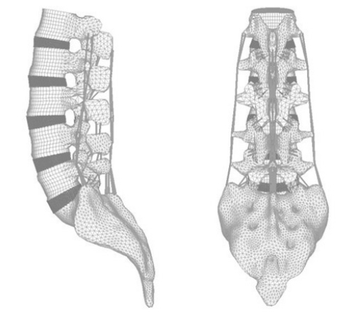
For development of a FEM, we obtained computed tomography (CT) images at 1 mm intervals on the intact lumbar spine (L1-S1) of a 21-year-old male with a height of 175 cm in height. The model was developed symmetrically based on the sagittal plane, and the vertebral body consisted of the cortical and cancellous bone. A 0.5 mm-thick end plate was inserted above and below the intervertebral disc, and the cartilage was inserted into the facet joint where superior and inferior articular processes contacted. The joint space was assumed at 0.5 mm with three-dimensional (3D) nonlinear contact.
A modeled intervertebral disc was inserted between vertebral bodies. The intervertebral disc was modeled with the annulus surrounding the nucleus pulposus at the center. The annulus consisted of 5 layers of the annulus ground substance and 6 layers of the annulus fibrosus that surrounded the substance in and out. The annulus fibrosus was positioned a mean of 30 degrees to the horizontal plane. The cross sectional area of the annulus was built to account for 19% of the annulus volume with the 3D linear elements applying only to the tensile load.
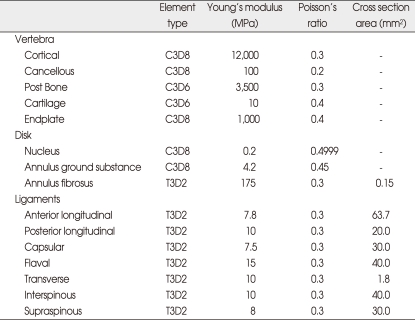
As a ligament connecting the vertebral body, 7 kinds of ligaments-anterior longitudinal ligament, posterior longitudinal ligament, transverse ligament, interspinous ligament, supraspinous ligament, capsular ligament, and ligament flavum-were inserted. Likewise, the ligament was modeled with the 3D linear elements applying only to the tensile load. Each location of the ligament was established according to the reference and anatomy data. By this method, the intact spinal finite element model of L1-S1 consisting of the vertebral body, intervertebral disc and ligaments was developed (Fig. 1). We referred to previous literature for material properties used to build the spinal model (Table 1)4,17,25).
Fig. 1.
Three-dimensional finite element model of lumbar spine L1-S1.
Table 1.
Material properties assigned to spinal components in the finite element model
Development of artificial disc finite element model
For comparison of different constrained types of an artificial disc, we selected Prodisc L® (a semi-constrained type artificial disc), Maverick® (a semi-constrained type that allows translation), and SB Charite III® (an unconstrained type). A 3D computer aided design (CAD) model for each artificial disc was developed based on respective drawings of Prodisc L®, Maverick®, and SB Charite III®. Prodisc L® and SB Charite III® consisted of an alloy of CoCrMo and CoCr-based upper and lower plates and a UHMWPE (Ultra High Molecular Weight Polyethylene) core while Maverick was composed of only CoCrMo. The material properties used in the development of the FEM were the ones reported by previous studies4,17,24). The polyethylene core and lower end plate of Prodisc L® were completely fixed, and 3D nonlinear contact conditions were added between the polyethylene core and the upper end plate. Maverick® consisted of upper and lower end plates without a core, and 3D nonlinear contact surface conditions were added between them. SB Charite III® was modeled to provide addition of 3D nonlinear contact surface conditions between the upper end plate and the polyethylene core and between the lower end plate and the polyethylene core. As reported by previous studies, friction coefficients of 0.07 and 0.02 were applied respectively to Prodisc L® and SB Charite III®. In case of Maverick®, 0.05, which was known as a friction coefficient for CoCrMo-based inserts, was applied since no previous data were available for Maverick.
The lordotic angle of the L4-5 intervertebral disc was 9.48 degrees, and the thickness was about 10 mm in the finite lumbar element model developed by this study. Accordingly, 11 degrees in the lordotic angle and 10 mm in height were used for Prodisc L®; 9 degrees in the lordotic angle and 10 mm in height, for Maverick®; and 10 degrees in the lordotic angle and 7.5 mm in the core height, for SB Charite III®. The most suitable form created with part of the bone end plate was inserted, with the height of the artificial disc main-tained at the height of the L4-5 intervertebral disc of the intact FEM. The artificial disc was implanted between L4-5, and each upper and lower surface of the artificial disc was completely fixed to vertebral end plates. The nucleus pulposus and anterior longitudinal ligament of the L4-5 intervertebral disc in which the artificial disc was implanted were completely removed, and partial annulus was also removed (Fig. 2). The artificial disc was implanted to be located at the center of the vertebral body.
Fig. 2.
Three-dimensional finite element model of L4-5 segment with artificial disc. A : Prodisc L® (Synthes Spine, West Chester, NY, USA). B : Maverick® (Medtronic Sofamor Danek, Inc., Memphis, TN, USA). C : SB Charite III® (DePuy spine, Raynham, MA, USA).
Loading and boundary conditions
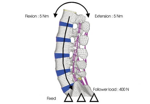
To verify the L1-S1 FEM, a flexion-extension pure moment of 5 Nm was added to the fixed sacrum. For comparison with previous experiments4,17,25) and analytic researches, we divided the flexion-extension moments applied in this study by the rotation angle of flexion-extension and defined it as "stiffness". The stiffness measured was compared with the results of previous experiments and analytic researches to validate the intact lumbar spinal model developed by this study.
A compressive force of 400 N was added to the validated intact lumbar spinal model in the follower load path direction as suggested by Patwardhan et al.21) Then, spinal segment motions were compared between a flexion-extension moment of 5 Nm and a same force of flexion-extension moment but without a compressive load. The validity of the follower load path used in this study was assessed by comparing the result with that of previous experimental studies4,17,25). The sacrum was completely fixed as it had been in the intact model (Fig. 3).
Fig. 3.
Boundary and loading conditions.
Each spinal segment motion, facet contact loads, and stress on the artificial intervertebral disc (von-Mises stress) were measured for each model under a compressive load of 400 N added in the follower load path and a flexion-extension moment of 5 Nm. The sacrum was completely fixed as it had been in previous experiments and analytic researches. For finite element interpretation and sequence conduction programs, ABAQUS™ (version 6.5, ABAQUS Inc., Providence, RI, USA) and FEMAP (version 8.20, Electronic Data Systems Corp., Plano, TX, USA) were used, respectively.
RESULTS
Verification of intact lumbar model and follower load condition
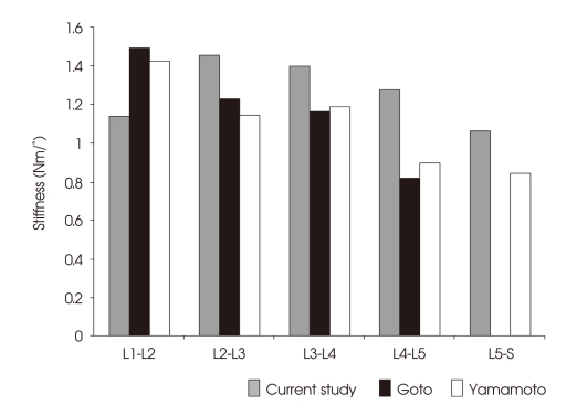
For verification, experimental results of the intact lumbar model were compared with the results of the Yamamoto27) experiment and the Goto analytic research12). The stiffness of the L1-2 segment was about 20% lower, and that of L2-3, L3-4, L4-5, and L5-S1 segments were 26%, 17%, 42%, and 25% greater, respectively, than the experiments. Although the stiffness of the L1-2 segment was found lower than the Yamamoto experiment, the values for each segment from L2 to S1 tended to decrease as the level went down (Fig. 4).
Fig. 4.
The validation of intact lumbar model via comparison of flexion/extension stiffness with published data.
To verify the validity of the compressive force in the follower load path direction, we compared spinal segment motions under compressive loads in the follower load path direction with flexion and extension moments added with the motions under pure flexion and extension moments. Then, the results were compared against the experimental research performed by Rohlmann et al.22) Their experimental conditions were somewhat different from ours, using L1-5, a compressive load in the follower load path direction of 280 N, and a flexion-extension moment of 7.5 Nm. According to their experiment, the rotation angle was measured 9% higher during flexion and 25% lower during extension when a compressive load and a flexion-extension moment were added than when only a flexion-extension moment was added. In this study, the rotation angle was observed 25% higher during flexion and 24% lower during extension when both a compressive load and a flexionextension moment were provided.
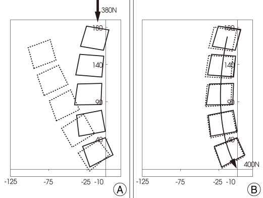
In addition, spinal segment motions of the intact spinal model were compared between a compressive load in the follower load path and a compressive load in the vertical direction. As a result, a load of 400 N in the follower load path direction demonstrated 2.45 degrees in flexion but a load of 380 N in the vertical direction showed a severe anterior flexion deformity at about 30 degrees (Fig. 5). At a 20 N lower load, the simple vertical direction indicated spinal rotation as great as 12 times.
Fig. 5.
The different motion of lumbar spine. A : Compressive vertical load path. B : Compressive follower load path.
Spinal segment motions of intact and artificial disc implanted models
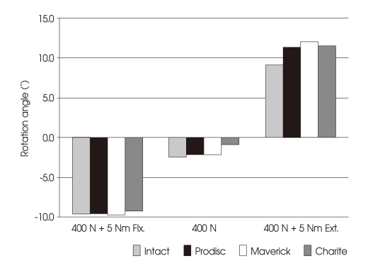
There were no significant differences in spinal segments between artificial disc implanted models and the intact lumbar model when a compressive load of 400 N and a flexion moment of 5 Nm were added. However, the intact model rotated about 9.1 degrees while the models implanted with Prodisc L®, Maverick®, and SB Charite III® artificial discs rotated 2.3, 2.9, and 2.4 degrees more, respectively, under a compressive load of 400 N and an extension moment of 5 Nm (Fig. 6).
Fig. 6.
Rotation angle during flexion/extension moments with follower preload. Flx.: Flexion, Ext : Extension.
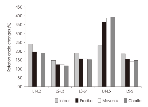
The rotation angle change under the extension load was examined at each spinal segment. The change of the artificial disc implanted segment (L4-5) was 23.3% in the intact model. However, the change was increased by 13.2%, 15.5%, and 15.8%, respectively, with Prodisc L®, Maverick®, and SB Charite III® implanted models when compared with the intact model. Moreover, the maximum standard deviation of the rotation angle at each segment to the total rotation angle was 9.4% in the intact model, but it increased to 24.0%, 26.2%, and 27.4%, respectively, in the models implanted with Prodisc L®, Maverick®, and SB Charite III® artificial discs (Fig. 7).
Fig. 7.
Intersegmental rotation angle changes during extension load.
The facet contact load
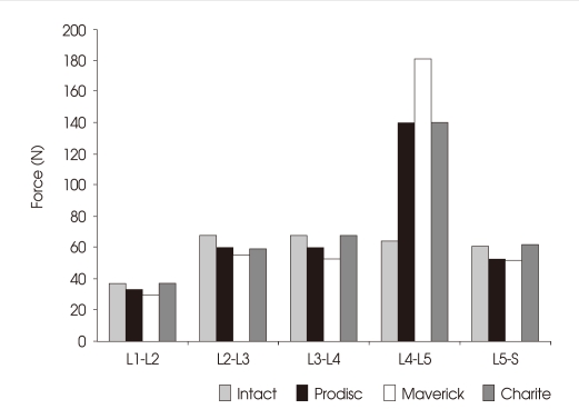
The facet contact load in the extension load condition was analyzed at each spinal segment. The facet contact load at the segment without artificial disc implantation did not show a significant difference. The L4-5 segment implanted with Prodisc L®, Maverick®, and SB Charite III® artificial discs demonstrated the contact load 2.2, 2.8, and 2.2 times greater than the segment in the intact model (Fig. 8).
Fig. 8.
Facet contact loads at lumbar motion segments during extension load.
Stress on artificial disc polyethylene insert (von-Mises stress)
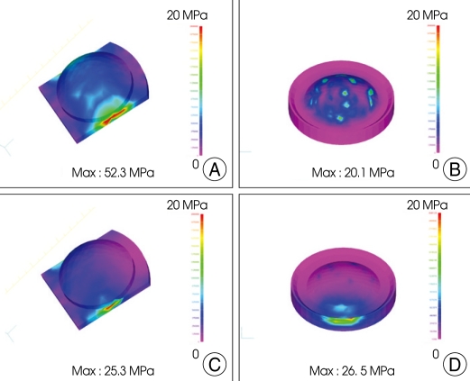
Under the flexion and extension load condition, stress on Prodisc L® and SB Charite III® polyethylene cores was analyzed. Of the three research materials, Prodisc L®, Maverick®, and SB Charite III®, Maverick® had a metal-on-metal method that did not allow implantation of a polyethylene core. Therefore, stress on the polyethylene core insert of the artificial disc could only be compared between Prodisc L® and SB Charite III®. No significant differences were found under the extension condition, with the stress on the polyethylene core insert measured at 25.3 MPa for Prodisc L® and 26.5 MPa for SB Charite III®. However, under the flexion condition, the maximum stress was 20.1 MPa for SB Charite III® and 52.3 MPa for Prodisc L, twice as great (Fig. 9).
Fig. 9.
von-Mises stress distribution on Ultra High Molecular Weight Polyethylene core in flexion/extension load : Prodisc L® (A and C), SB Charite III® (B and D).
DISCUSSION
For the treatment of chronic discogenic low back pain, total disc replacement that preserves segment motions better than spinal fusion has gained increasing interests, and studies based on clinical experiments and finite element interpretation have been published1,7,10,12,15,20-23). However, the efficacy of total disc replacement remains controversial3,9,24). Although individual researches on Prodisc L®, Maverick ®, and SB Charite III® artificial discs have been made, a biomechanical analysis of the artificial discs under the same condition has not yet been reported. Based on the finite element interpretation technique, the present study performed a biomechanical analysis of spinal models implanted with the three most commonly used types of an artificial disc under the same load and restraint conditions and compared the result with that of the intact spinal model. The FEM has been widely used for a biomechanical analysis of the spine as it compares results between different specimens without a deviation and analyzes results quantitatively13,16,20). However, it has a disadvantage that the experience of an experimenter can influence results because only the conditions provided are used.
In a biomechanical research based on finite element interpretation, the model to be experimented should be verified before the experiment starts. Accordingly, the intact finite element model, which had been developed for the research purpose, was verified against previous research results. Spinal segment motions under pure flexion and extension moments with the sacrum in a fixed state were compared with the Yamamoto et al.27) experimentet and Goto et al.12) interpretation research. As a result, the stiffness of the L1-2 segment in our study was measured lower, but overall, a similar spinal motion tendency was recognized. In addition, spinal motions under a compressive load in the follower load path corresponded to the research result of Rohlmann et al.22). Previous studies have reported that buckling occurs in the spine under a load of 80-100 N1). We observed a severe deformity of the model under a vertical load of 280 N, but the model remained relatively stable under a compressive load in the follower load path. Through this process, the spinal model and description of the follower path load developed in this study were considered valid for research.
Recent literature has described total disc replacement using a Charite III artificial disc as a safe and effective treatment method in the short term for lower lumbar lesions caused by degenerative disc diseases at L4-5 or L5-S1 segments3). Total disc replacement with a Charite® artificial disc has shown well-maintained flexion and extension motions at 24 months after operation11). Biomechanical research papers on functional properties of Prodisc®, Maverick®, and Charite® also found all 3 types effective in recovery of flexion and extension motions. Kim et al.15) reported that the rotation angle decreased 13% under the flexion load and increased 90% under the extension load. The total flexion and extension rotation angle in the spinal model increased 33% when compared with the intact model. Hitchon et al.14) showed that a spinal model implanted with a Maverick® artificial disc had a 50% larger rotation angle during flexion, and a 30% larger angle during extension. Cunningham et al.7) also stated that the flexion-extension rotation angle of the spine implanted with a Charite® artificial disc increased 3% from the angle of the intact spine. In the present study, the Prodisc® implanted model showed a 6% decrease in flexion and a 57% increase in extension. Overall, the rotation angle increased 11%, coinciding with the result of research by Kim et al.15). The Maverick® implanted model showed movements similar to those of the intact model in flexion, but the movements increased 30% in extension, as reported by Hitchon et al.14) While Hitchon et al.14) removed the posterior longitudinal ligament that affected flexion rotation, we preserved it in this research. This may have contributed to the different result in the spinal rotation angle of the artificial disc implanted model during flexion motions. The Charite® implanted model indicated a 10% increase in the flexion-extension rotation angle when compared with the intact model.
Previous research data have also supported that the rotation angle of the segments implanted with an artificial disc increases significantly under the extension load, which may affect the facet joint. Thus, we evaluated biomechanical changes of the facet by measuring the facet contact load. As a result, the facet contact load was found higher in the segments implanted with artificial discs than in the segments of the intact model.
A large facet contact load under the extension load can induce back pain during extension motions, as frequently reported3,10,17,24). Citing hyperextension of the operative site as a reason for recurred or persistent pain in the patients who had undergone total disc replacement for lower limb lesions, van Ooij et al.24) insisted that hyperextension increased a compressive load on the facet, leading to facet arthritis. There may be various factors that cause hyperextension of operative segments, but removal of the longitudinal ligament for artificial disc implantation, incorrect location of an artificial disc, and improper design or fixation of an artificial implant are cited as representative factors among others.
It is inevitable that the anterior longitudinal ligament be removed at the implantation of an artificial disc through the anterior approach. This causes loss of the anterior binding force during extension motions, inducing hyperextension. Rohlmann et al.23) suggested combination of anterior longitudinal ligament reconstruction to overcome this problem. For another reason, David8) also claimed in his research on the Charite® artificial disc revision replacement that the anterior longitudinal ligament and the circumferential ligament should be sutured after artificial disc implantation as it would reduce the formation of scar tissue in the operative area and prevent dislocation of the injured implant from the intervertebral disc space upon injury occurred during long-term postoperative follow-up, which would minimize the risk of complications in re-operation. Therefore, suturing the anterior longitudinal ligament after total disc replacement is recommended, if possible.
In total disc replacement, selection of the location for artificial disc implantation is very important because of its proximity to the normal flexion-extension rotation center. White and Panjabi26) indicated that the intact lumbar rotation center was located posterior to the intervertebral disc in flexion-extension motions. van Ooij et al.24) insisted that if the rotation center of the artificial disc was not located posterior, the facet would come under excessive pressure during segmental motions, causing degenerative changes in the facet. In studies using a Maverick artificial disc, Le Huec et al.17) and Dooris et al.10) reported that the artificial disc implanted in the anterior direction would increase the facet contact load 2.5 times during extension motions. Thus, they stressed that the posterior margin of the artificial disc should be located within 7 mm from the posterior margin of the spinal end plate to reduce the facet contact load and prevent postoperative facet arthrosis. McAffe et al.18) observed clinical improvement and increased flexion-extension range of motions in the group that had a Charite artificial disc implanted at the ideal location.
With regard to the design of artificial discs, van Ooij et al.24) described that the rotation center during flexion-extension motions was placed somewhat posterior to the center of the intervertebral disc from the lateral view in intact segments while the rotation center in the Charite® or Prodisc® artificial disc was located at the center or somewhat anterior to the disc. They have noted that the design of these artificial discs did not reproduce intact spinal segment motions. Our study, however, did not observe significant differences in lumbar flexion and extension motions between the three design types, Prodisc®, Maverick®, and Charite®. Thus, when it comes to these artificial discs that are clinically being used, the location of implantation rather than the design seems to have a great impact on clinical improvement and recovery of spinal motions. Additional research and improvement may be required later for the design of an artificial disc. However, this result does not coincide with the result of Chung et al.6) who reported clear biomechanical differences between Prodisc® and Charite®. Such differences may have been resulted from the fact that Chung et al.6) considered more factors in their study for comparison, built a FEM only with L4-5 and used a simple moment load. On the other hand, we developed a FEM consisting of the whole spine for better physiologic conditions and used a follower load. In addition, the present study showed higher facet stress in the Charite® artificial disc, another different observation with Chung's study6). We believe the difference is the result of different experimental conditions as previous studies have also found differences according to experimenters. To validate differences between various FEM results, further studies are considered necessary.
The maximum load on the polyethylene core implanted with Prodisc L® under flexion was 52.3 MPa. Previous researches have reported yield stress on UHMWPE, material of the polyethylene core, to be about 20 MPa2). Although the absolute value of each maximum load is not significant due to the nature of interpretation methods, a yield stress of 20 MPa on the polyethylene core is considered high. In this regard, in case of Prodisc L®, yield stress on the polyethylene core in a moment under the flexion load may expose the disc to injury. Both Prodisc L® and SB Charite III® showed stress higher than yield stress, though only slightly higher, not only in flexion but also in extension motions. Such load conditions may affect the injury of artificial discs in the long term.
The limitation of this study is that we mainly focused on the stress on the polyethylene core and the facet in FEM during flexion-extension motions and did not analyze outcomes from other planes. Further studies that overcome this limitation are considered necessary.
Total disc replacement has the advantage of preventing the adjacent segmental intervertebral disc injury that occurs in long-term spinal fixation3). However, little has been reported on multiple total disc replacement involving more than 2 segments and conjoinment of spinal fusion, and total disc replacement has many problems to overcome. Therefore, additional research on the improvement of surgical techniques should be conducted for multiple-segment total disc replacement and its conjoinment with spinal fusion.
CONCLUSION
The biomechanical analysis of Prodisc L®, Maverick®, and SB Charite III® under flexion and extension loads did not show significant differences between the three artificial disc types. All the models implanted with artificial discs demonstrated spinal motions similar to those of the intact model during flexion. However, during extension, the rotation angle at the operated site (L4-5) was measured larger in the artificial disc implanted models than in the intact model, which led to an increase in the facet contact load. The increased facet load may result in facet degeneration. In addition, Prodisc L® had stress greater than yield stress under the flexion load, which may expose the disc to injury. To overcome the re-maining problems with artificial intervertebral discs, new surgical techniques and new designs for artificial discs are considered necessary.
References
- 1.Ahn MW, Shin KS, Lee JW, Chung IS, Lee CY. Analysis of compression behavior in lumbar spine under simple vertical load vs follower load. J Korean Soc Spine Surg. 2002;9:78–83. [Google Scholar]
- 2.Baker DA, Hastings RS, Pruitt L. Study of fatigue resistance of chemical and radiation cross linked medical grade ultrahigh molecular weight polyethylene. J Biomed Mater Res. 1999;46:573–581. doi: 10.1002/(sici)1097-4636(19990915)46:4<573::aid-jbm16>3.0.co;2-a. [DOI] [PubMed] [Google Scholar]
- 3.Freeman BJ, Davenport J. Total disc replacement in the lumbar spine : a systematic review of the literature. Eur Spine J. 2006;15:S439–S447. doi: 10.1007/s00586-006-0186-9. [DOI] [PMC free article] [PubMed] [Google Scholar]
- 4.Chen CS, Feng CK, Cheng CK, Tzeng MJ, Liu CL, Chen WJ. Biomechanical analysis of the disc adjacent to posterolateral fusion with laminectomy in lumbar spine. J Spinal Disorders Tech. 2005;18:58–65. doi: 10.1097/01.bsd.0000123426.12852.e7. [DOI] [PubMed] [Google Scholar]
- 5.Chen WJ, Lai PL, Niu CC, Chen LH, Fu TS, Wong CB. Surgical treatment of adjacent instability after lumbar spine fusion. Spine. 2001;26:E519–E524. doi: 10.1097/00007632-200111150-00024. [DOI] [PubMed] [Google Scholar]
- 6.Chung SK, Kim YE, Wang KC. Biomechanical effect of constraint in lumbar total disc replacement : a study with finite element analysis. Spine (Phila Pa 1976) 2009;34:1281–1286. doi: 10.1097/BRS.0b013e3181a4ec2d. [DOI] [PubMed] [Google Scholar]
- 7.Cunningham BW, Gordon JD, Dmitriev AE, Hu N, McAfee PC. Biomechanical evaluation of total disc replacement arthroplasty : an in vitro human cadaveric model. Spine (Phila Pa 1976) 2003;28:S110–S117. doi: 10.1097/01.BRS.0000092209.27573.90. [DOI] [PubMed] [Google Scholar]
- 8.David T. Revision of a Charité artificial disc 9.5 years in vivo to a new Charité artificial disc : case report and explant analysis. Eur Spine J. 2005;14:507–511. doi: 10.1007/s00586-004-0842-x. [DOI] [PMC free article] [PubMed] [Google Scholar]
- 9.de Kleuver M, Oner FC, Jacobs WC. Total disc replacement for chronic low back pain : background and a systematic review of the literature. Eur Spine J. 2003;12:108–116. doi: 10.1007/s00586-002-0500-0. [DOI] [PMC free article] [PubMed] [Google Scholar]
- 10.Dooris AP, Goel VK, Grosland NM, Gilbertson LG, Wilder DG. Load-sharing between anterior and posterior elements in a lumbar motion segment implanted with an artificial disc. Spine (Phila Pa 1976) 2001;26:E122–E129. doi: 10.1097/00007632-200103150-00004. [DOI] [PubMed] [Google Scholar]
- 11.Geisler FH, Blumenthal SL, Guyer RD, McAfee PC, Regan JJ, Johnson JP, et al. Neurological complications of lumbar artificial disc replacement and comparison of clinical results with those related to lumbar arthrodesis in the literature : results of a multicenter, prospective, randomized investigational device exemption study of Charité intervertebral disc. Invited submission from the Joint Section Meeting on Disorders of the Spine and Peripheral Nerves, March 2004. J Neurosurg Spine. 2004;1:143–154. doi: 10.3171/spi.2004.1.2.0143. [DOI] [PubMed] [Google Scholar]
- 12.Goto K, Tajima N, Chosa E, Totoribe K, Kubo S, Kuroki H, et al. Effects of lumbar spinal fusion on the other lumbar intervertebral levels (three-dimensional finite element analysis) J Orthop Sci. 2003;8:577–584. doi: 10.1007/s00776-003-0675-1. [DOI] [PubMed] [Google Scholar]
- 13.Ha SK. Finite element modeling of multi-level cervical spinal segments (C3-C6) and biomechanical analysis of an elastomer-type prosthetic disc. Med Eng Phys. 2006;28:534–541. doi: 10.1016/j.medengphy.2005.09.006. [DOI] [PubMed] [Google Scholar]
- 14.Hitchon PW, Eichholz K, Barry C, Rubenbauer P, Ingalhalikar A, Nakamura S, et al. Biomechanical studies of an artificial disc implant in the human cadaveric spine. J Neurosurg Spine. 2005;2:339–343. doi: 10.3171/spi.2005.2.3.0339. [DOI] [PubMed] [Google Scholar]
- 15.Kim YE, Yun SS, Jung SK. Biomechanical analysis of the implanted constrained and unconstrained ICR types of artificial disc using FE model. J of the KSPE. 2006;23:176–182. [Google Scholar]
- 16.Kumaresan S, Yoganandan N, Pintar FA, Maiman DJ. Finite element modeling of the cervical spine : role of intervertebral disc under axial and eccentric loads. Med Eng Physics. 1999;21:689–700. doi: 10.1016/s1350-4533(00)00002-3. [DOI] [PubMed] [Google Scholar]
- 17.Le Huec JC, Basso Y, Aunoble S, Friesem T, Bruno MB. Influence of facet and posterior muscle degeneration on clinical results of lumbar total disc replacement : two-year follow-up. J Spinal Disord Tech. 2005;18:219–223. [PubMed] [Google Scholar]
- 18.McAfee PC, Cunningham B, Holsapple G, Adams K, Blumenthal S, Guyer RD, et al. A prospective, randomized, multicenter Food and Drug Administration investigational device exemption study of lumbar total disc replacement with the CHARITE artificial disc versus lumbar fusion : part II : evaluation of radiographic outcomes and correlation of surgical technique accuracy with clinical outcomes. Spine (Phila Pa 1976) 2005;30:1576–1583. doi: 10.1097/01.brs.0000170561.25636.1c. discussion E388-E390. [DOI] [PubMed] [Google Scholar]
- 19.Natarajan RN, Andersson GB. The influence of lumbar disc height and cross-sectional area on the mechanical response of the disc to physiologic loading. Spine (Phila Pa 1976) 1999;24:1873–1881. doi: 10.1097/00007632-199909150-00003. [DOI] [PubMed] [Google Scholar]
- 20.Ng HW, Teo EC, Lee VS. Statistical factorial analysis on the material property sensitivity of the mechanical responses of the C4-C6 under compression, anterior and posterior shear. J Biomech. 2004;37:771–777. doi: 10.1016/j.jbiomech.2003.09.025. [DOI] [PubMed] [Google Scholar]
- 21.Patwardhan AG, Havey RM, Meade KP, Lee B, Dunlap B. A follower load increases the load-carrying capacity of the lumbar spine in compression. Spine (Phila Pa 1976) 1999;24:1003–1009. doi: 10.1097/00007632-199905150-00014. [DOI] [PubMed] [Google Scholar]
- 22.Rohlmann A, Neller S, Claes L, Bergmann G, Wilke HJ. Influence of a follower load on intradiscal pressure and intersegmental rotation of the lumbar spine. Spine (Phila Pa 1976) 2001;26:E557–E561. doi: 10.1097/00007632-200112150-00014. [DOI] [PubMed] [Google Scholar]
- 23.Rohlmann A, Zander T, Bergmann G. Effect of total disc replacement with prodisc on intersegmental rotation of the lumbar spine. Spine (Phila Pa 1976) 2005;30:738–743. doi: 10.1097/01.brs.0000157413.72276.c4. [DOI] [PubMed] [Google Scholar]
- 24.van Ooij A, Oner FC, Verbout AJ. Complications of artificial disc replacement : a report of 27 patients with the SB Charité disc. J Spinal Disord Tech. 2003;16:369–383. doi: 10.1097/00024720-200308000-00009. [DOI] [PubMed] [Google Scholar]
- 25.Wang JL, Parnianpour M, Shirazi-Adl A, Engin AE. Rate effect on sharing of passive lumbar motion segment under load-controlled sagittal flexion : viscoelastic finite element analysis. Theoretical and Applied Fracture Mechanics. 1999;32:119–128. [Google Scholar]
- 26.White AA, III, Panjabi MM. Clinical biomechanics of the spine. Philadelphia: Lippincott; 1978. p. 81. [Google Scholar]
- 27.Yamamoto I, Panjabi MM, Crisco T, Oxland T. Three-dimensional movements of the whole lumbar spine and lumbosacral joint. Spine (Phila Pa 1976) 1989;14:1256–1260. doi: 10.1097/00007632-198911000-00020. [DOI] [PubMed] [Google Scholar]


