Abstract
We developed a method to assess the accuracy of an image-free resurfacing hip arthroplasty navigation system in a proximal femur with normal and abnormal anatomy. A phantom lower limb allowed deformation in varus/valgus and ante-retroversion. At specific points during the simulated surgical procedure, information was compared between a digital caliper and the computer navigation system angular measurements. Repeated serial tests were undertaken. In the setting of normal anatomical alignment of the proximal femur, the mean error of the system characterised as the difference between the measured computer navigation and caliper angles was 0.6° in the frontal plane and 3.4° in the lateral plane. In the setting of abnormal anatomical alignment, the mean error was 0.4° in the frontal plane and 2.1° in the lateral plane. This is the first study designed to assess the accuracy of a femoral navigation system for resurfacing hip arthroplasty in normal settings and in the presence of angular deformity. The study demonstrates satisfactory in-vitro accuracy.
Résumé
Nous avons développé pour le resurfaçage de la hanche une méthode d’évaluation de la navigation sans image au niveau du fémur proximal sur des fémurs normaux et anormaux. Un fantôme de membre inférieur montrant des déformations en varus et en valgus ainsi qu’en anteversion a été utilisé. Dans le cadre d’un fémur normalement aligné, l’erreur moyenne est caractérisée par la différence entre la mesure de la navigation et l’angle mesuré par le gonomètre de 0,6° dans le plan frontal, de 3,4° dans le plan profil. Dans le cadre d’un fémur anormalement aligné, l’erreur moyenne a été de 0,4° dans le plan frontal et de 2,1° pour le profil. Il s’agit de la première étude montrant l’intérêt de la navigation lors du resurfaçage de la hanche qu’il s’agisse d’un fémur normal ou qu’il s’agisse d’un fémur déformé. Cette étude in vitro est satisfaisante.
Introduction
Correct positioning of the femoral component in resurfacing hip arthroplasty (RHA) has been shown to be an important factor in successful long-term outcome [2, 4]. Recent advances in computer-assisted navigation technology (CAS) address the several fundamental limitations inherent in conventional alignment and implant positioning tools for total hip and knee arthroplasty [4, 6, 11, 13, 15, 16]. More recently, CAS tools have been used in clinical settings for RHA navigation; however, clinical experience and radiological outcomes of CAS applications in RHA are still limited [1, 7], and little is known about their accuracy [5].
The objectives of our study were: (1) to design and develop a method to assess the accuracy of an image-free infrared technology CAS navigation system for RHA, and (2) to assess its accuracy in an experimental model with both normal anatomy and with angular deformity of the neck/head segment.
Material and methods
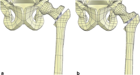
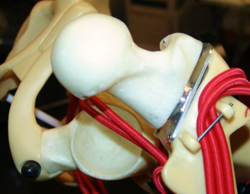
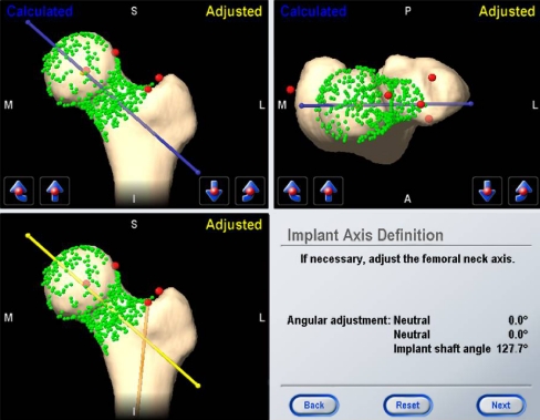
A leg phantom (Version 3, Medical Models Ltd., Middlesex, UK) designed for in vitro surgical training of CAS resurfacing hip arthroplasty was modified to allow for a simulation of normal and deformed proximal femur alignment. The modification involved fixation of a square aluminium block and aluminium 10° adapter wedges at the base of the femoral neck (Fig. 1). The block and wedges provided a rigid connection with the predetermined angle between the femur axis and the femoral neck and head segment (Fig. 2). The Kolibri navigation system (BrainLab, Munich, Germany) with dedicated ASR software (DePuy, Leeds, UK) requires various landmark points to establish the femoral shaft axis, the femoral neck axis, and the frontal plane of the leg in order to assist the surgeon in the placement of the guide wire for reaming of the femoral head. The femoral shaft axis runs from the point midway between the medial and lateral epicondyles to the femoral neck base point, which is arbitrarily positioned in the vicinity of the piriformis fossa. The proximal femur axis is calculated from a multitude of points registered on the anterior, superior, posterior, and inferior faces of the femoral neck. The stem–shaft angle is then calculated in reference to the frontal plane of the leg. The frontal plane is defined by three points, namely, the mid-point between the two epicondyles, the femoral neck base point, and the centre of rotation of the femoral head (Fig. 3). The medial and lateral epicondyles, the greater trochanter, the neck base point, and the sizing point (crucial for implant positioning and sizing) were marked with grub screws, which were inserted into the leg phantom to ensure their reproducible acquisition throughout the study. An additional grub screw was inserted along the femoral shaft, which was required for control calculations. After setting up the leg phantom with the respective deformity we then conducted the operation in accordance with the CAS system procedure to insert the reference drill guide into the femoral head and neck segment. The implant shaft angle and the deviations of the computed trajectory in the frontal and axial planes registered by the CAS system were recorded. We used three tools to assess the CAS system’s accuracy: (1) an X-ray micro-tomograph (SkyScan 1172, SkyScan, Belgium) was used to scan the femoral head component in order to determine the 3D trajectory of the guide wire; (2) a coordinate measurement digital caliper (FaroArm S06/REV 22, Faro Technologies Inc., USA) was used to acquire the 3D coordinates of the phantom leg using anatomical landmarks (medial and lateral epicondyles, a point along the femoral shaft, the neck base point), as well as to determine the 3D coordinates of the femoral component alignment guide using three landmark points taken along the guide; (3) a 3D model of the femoral head and computer aided design (CAD) software (SolidWorks 2007, SolidWorks Corporation, USA) was used to calculate the centre of rotation. The centre of rotation of the hip joint was constant throughout the study, as 15 specimens of the same 3D model were used for the measurements. All other landmark points or the femoral neck axis were individually measured during each CAS procedure. The coordinate data and images were processed and the implant shaft angle computed using a computer program written in MATLAB (The MathWorks, USA). Five sets of experiments were conducted: a repetition study of three measurements with neutral femoral head and neck alignment (127° of CCD angle, 15° of neck/head segment anteversion) and three repeated measurements with deformed alignment of the neck/head segment (10˚ respectively in varus, valgus, anteversion, and retroversion), totalling 15 measurements. In all measurements, we aimed to position the guide with an implant–shaft angle of 127° (Fig. 4). This angle was chosen to facilitate the measurement process. In clinical settings, an implant–shaft angle of 130–135° or more is recommended.
Fig. 1.
Drawing of the phantom femur designed to simulate anatomical alignment and various deformities of the head and neck segment. a 10° varus. b 10° valgus
Fig. 2.
Close-up of the phantom with normal anatomy
Fig. 3.
Reference points for definition of the frontal plane
Fig. 4.
The CAS proximal femur morphed model indicates the implant shaft angle and the lateral plane “neutral” alignment of the head and neck segment in normal anatomical settings
Results
The mean measured difference between the CAS system and calculated angles with the FARO arm in the normal anatomical settings was 0.6° in the frontal plane (confidence intervals 0.4–0.7°) and 3.4° in the lateral plane (confidence intervals 2.7–4.1°). The overall mean measured difference between the CAS system and calculated angles in the abnormal anatomy settings was 0.4° in the frontal plane (confidence intervals 0.3–0.5°) and 2.1° in the lateral plane (confidence intervals 1.1–3.1°). Table 1 shows the measured difference between CAS and calculated angles in the 10° frontal deformity and 10° neck version deformity. A paired two-tailed t test was performed on each measurement set that included the neutral measurement and the four simulated deformities with CAS and the FARO electronic caliper. The difference between the two measurements was statistically significant (p < 0.05) for the normal anatomy in the frontal plane, but not for any of the simulated deformities in the frontal plane. There was no statistical significance in the lateral plane for any of the data sets.
Table 1.
Mean difference and 95% confidence intervals (CI) of the measured difference between the computer navigation system and angles calculated with an electronic caliper
| Deformity | Mean | 95% CI |
|---|---|---|
| Varus–valgus deformity, frontal plane | 0.42° | 0.07° and 0.77° |
| Varus–valgus deformity, lateral plane | 2.84° | 1.64° and 4.04° |
| Ante-/retroversion, frontal plane | 0.45° | 0.23° and 0.68° |
| Ante-/retroversion, lateral plane | 1.15° | 0.19° and 2.11° |
Each displayed angle is the average of three measurements
Discussion
To our knowledge, this is the first study designed to assess accuracy of an image-free CAS navigation system for RHA in normal anatomy and angular deformity settings. For this purpose, we built a mechanical phantom in conjunction with a precision coordinate measuring system. A similar experimental model was used to assess accuracy of CAS in total knee arthroplasty [12]. Our study demonstrates a satisfactory level of accuracy of the Kolibri system. So far, no comparisons exist between different CAS navigation systems for RHA in the literature. Use of standards for pre-clinical validation of CAS systems is needed, and this study is a first attempt to address this issue.
RHA is technically demanding and time consuming and has been associated with greater implant placement variability [14]. The insertion of the RHA femoral component using conventional tools relies on the freehand placement of a femoral guide wire, based on estimates of optimal positioning from pre-operative imaging and surgical jigs. Such estimates introduce imprecision and may result in malpositioning and notching of the femoral neck [9]. These results are associated with an increased incidence of femoral neck fracture and early implant failure [2, 4, 14]. In view of these problems, the application of CAS navigation technology in RHA appears reasonable. Computer navigation improves implant positioning and may prolong survivorship in total hip and knee replacement arthroplasty [3, 15]. However, there is a paucity of experimental and clinical data relative to CAS applications in RHA. The purposes of CAS systems in RHA are to insert the femoral neck guide wire with greater accuracy and to help in sizing the femoral component. Pre-clinical trials of various CAS navigation systems have demonstrated consistent reproducibility of precise guide pin placement and optimum implant–shaft angle [1, 3]. Analyses in synthetic models, cadaver models, and in the clinical setting have shown that computer navigation significantly reduces implant positioning variability [1, 7–9]. These results seem to be independent of surgeon experience [3, 9]. Davis et al. [5], in a cadaver study, reported a range of error of implant–shaft angle position of 15° (SD 4.2°) with conventional tools and only 8° (SD 2.9°) with CAS technology. In contrast, Krueger et al. [10], in a clinical trial, reported no difference of femoral component position between CAS and conventional RHA.
This study has some limitations. First, the use of head specimens with the same shape impaired the ability to determine CAS accuracy of implant sizing. Secondly, the Kolibri CAS system does not report the absolute angle values of the head and neck version in the lateral plane. However, the system indicates to the surgeon the ideal “neutral” positioning of the guide wire passing through the centre of the femoral head and along the anatomical axis of the neck in the axial plane. Subsequently, we needed to calculate the ante- and retroversion CAS angle values using the lateral alignment adjustment tool in reference to the intercondylar axis. It is recognised that this is a poor approximation, but insofar as the study was performed by always using the same registration points in the epicondylar area, we believe that this limitation has been minimised. Unfortunately, we had no access to the algorithm software of the CAS system to verify our indirect measurement of the ante- and retroversion alignment. Certainly, the lack of the CAS version angle values in clinical settings can be problematic. On the other hand, surgeons habitually aim to align the femoral component in the lateral plane according to the patient anatomy; correction of abnormal ante- or retroversion of the head and neck segment is usually not indicated in RHA [13].
This study was designed to determine accuracy of the Kolibri CAS system in the presence of angular deformity of the neck/head segment. A frequent deformity seen in Caucasian patients requiring RHA is the so-called pistol-grip configuration of the head and neck segment; presence of this deformity can be a challenge for the surgeon because of the risk of notching and of mal-positioning of the femoral component. Accuracy of the Kolibri CAS system in these settings was not tested in our study.
In conclusion, this experimental study shows accurate femoral CAS navigation in RHA using the image-free Kolibri system. The mean error of the system characterised as the difference between the measured CAS angles and experimental verification angles ranged between 0.4° and 0.6° in the frontal plane and between 2.1° and 3.4° in the lateral plane. In clinical settings, we expect lower accuracy with larger variations, caused by factors like registration errors of anatomical landmarks and erroneous execution of the CAS algorithm protocol.
Acknowledgements
The authors wish to thank Vinod Suresh for statistical analysis assistance and Lawrence Anderson for preparation of the technical drawings.
References
- 1.Barrett ARW, Davies BL, Gomes MPSF, et al. Computer-assisted hip resurfacing surgery using the Acrobot navigation system. J Eng Med. 2007;221:773–785. doi: 10.1243/09544119JEIM283. [DOI] [PubMed] [Google Scholar]
- 2.Beaule PE, Lee JL, Duff MJ, et al. Orientation of the femoral component in surface arthroplasty of the hip: a biomechanical and clinical analysis. J Bone Joint Surg [Am] 2004;86-A:2015–2021. doi: 10.2106/00004623-200409000-00021. [DOI] [PubMed] [Google Scholar]
- 3.Cobb JP, Kannan V, Brust K, Thevendan G. Navigation reduces the learning curve in resurfacing total hip arthroplasty. Clin Orthop Rel Res. 2007;463:90–97. doi: 10.1097/BLO.0b013e318126c0a5. [DOI] [PubMed] [Google Scholar]
- 4.Daniel J, Pynsent PB, McMinn DJ. Metal on metal resurfacing of the hip in patients under the age of 55 years with osteoarthritis. J Bone Joint Surgery [Br] 2004;86:177–184. doi: 10.1302/0301-620X.86B2.14600. [DOI] [PubMed] [Google Scholar]
- 5.Davis ET, Gallie P, Macgroarty K, et al. The accuracy of image-free computer navigation in the placement of the femoral component of the Birmingham Hip Resurfacing. A cadaveric study. J Bone Joint Surgery [Br] 2007;89:557–560. doi: 10.1302/0301-620X.89B4.17893. [DOI] [PubMed] [Google Scholar]
- 6.Dorr LD, Hishiki Y, Wan Z, et al. Development of imageless computer navigation for acetabular component position in total hip replacement. Iowa Orthop J. 2005;25:1–9. [PMC free article] [PubMed] [Google Scholar]
- 7.Hess T, Gampe T, Kottgen C, Szawlowski B. Intraoperative navigation for hip resurfacing: methods and first results. Orthopade. 2004;33:1183–1193. doi: 10.1007/s00132-004-0693-5. [DOI] [PubMed] [Google Scholar]
- 8.Hodgson AJ, Inkpen KB, Shekhman M, et al. Computer-assisted femoral head resurfacing. Comput Aided Surg. 2005;10:337–343. doi: 10.1080/10929080500379440. [DOI] [PubMed] [Google Scholar]
- 9.Hodgson A, Helmy N, Masri BA, et al. Comparative repeatability of guide-pin axis positioning in computer-assisted and manual femoral head resurfacing arthroplasty. Proc Inst Mech Eng. 2007;221:713–724. doi: 10.1243/09544119JEIM284. [DOI] [PubMed] [Google Scholar]
- 10.Krüger S, Zambelli PY, Leyvraz PF, Jolles BM (2007) Computer-assisted placement technique in hip resurfacing arthroplasty: improvement in accuracy? Int Orthop. Online First 24 Aug 2007 [DOI] [PMC free article] [PubMed]
- 11.Leenders T, Vandevelde D, Mahieu G, Nuyts R. Reduction in variability of acetabular cup abduction using computer assisted surgery: a prospective and randomized study. Comput Aided Surg. 2002;7:99–106. doi: 10.3109/10929080209146021. [DOI] [PubMed] [Google Scholar]
- 12.Pitto RP, Graydon AJ, Bradley L, et al. Accuracy of a computer assisted navigation system for total knee replacement. J Bone Joint Surg [Br] 2006;88:601–605. doi: 10.1302/0301-620X.88B5.17431. [DOI] [PubMed] [Google Scholar]
- 13.Pitto RP (2008) The trochanteric slide osteotomy approach for resurfacing hip arthroplasty. Int Orthop. Online First 21 May 2008 [DOI] [PMC free article] [PubMed]
- 14.Shimmin AJ, Back D. Femoral neck fractures following Birmingham hip resurfacing. A. national review of 50 cases. J Bone Joint Surg [Br] 2005;87:463–464. doi: 10.1302/0301-620X.87B4.15498. [DOI] [PubMed] [Google Scholar]
- 15.Sikorski JM, Chauhan S. Computer-assisted orthopaedic surgery: do we need CAOS? J Bone Joint Surg. 2003;85:319–323. doi: 10.1302/0301-620X.85B3.14212. [DOI] [PubMed] [Google Scholar]
- 16.Sparmann M, Wolke B, Czupalla H. Positioning of total knee arthroplasty with and without navigation support. J Bone Joint Surg [Br] 2003;85:830–835. [PubMed] [Google Scholar]


