Abstract
We evaluated the influence of CT-free or CT-based computer assisted orthopaedic surgery (CAOS) on the alignment of total knee prostheses (TK) and micromotion of tibial components. This randomised study compared 19 CT-free, 17 CT-based CAOS TK, and a matched control group of 21 conventionally placed TK. Using Roentgen stereophotogrammetric analysis (RSA) the migration was measured. The alignment and component positions were measured on radiographs. No significant difference in leg and tibial component alignment was present between the three groups. A significant difference was found for micromotion in subsidence, with the conventional group having a mean of 0.16 mm, compared to the CT-free group at 0.01 mm and the CT-based group at −0.05 mm. No clinical significant difference in alignment was found between CAOS and conventionally operated TK. More subsidence of the tibial component was seen in the conventional group compared to both CAOS groups at two year follow-up.
Résumé
But de l'étude: Evaluer l'influence de la navigation avec ou sans scanner sur l'alignement des prothèses totales du genou et sur la micromobilité du composant tibial. Matériel et méthode: nous avons réalisé une étude randomisée comparant 19 prothèses naviguées sans scanner, 17 prothèses naviguées avec scanner, croisées avec un groupe contrôle de 21 patients avec mise en place d'une prothèse par voie conventionnelle. Nous avons utilisé la méthode RSA pour mesurer la migration. L'alignement et les composants étaient mesurés sur les radiographies. Résultats: il n'y a pas de différence significative au niveau de l'alignement des composants pour les trois groupes, par contre il existe une différence significative en ce qui concerne la migration. Dans le groupe conventionnel celle-ci est d'environ 0,16 mm, 0,01 mm dans le groupe navigation sans scanner et 0,05 mm dans le groupe navigation avec scanner. Conclusion: il n'y a pas de différence significative dans l'alignement des prothèses totales du genou lors de la mise en place d'une prothèse totale avec ou sans navigation par contre, il existe une micromobilité avec petite migration du composant tibial si l'on compare le groupe conventionnel avec les groupes navigués.
Introduction
Alignment has been shown to be an important factor in survival of total knee prostheses (TK) [1, 10, 22]. Varus or valgus alignment of more than three degrees is associated with aseptic loosening, decrease of the prosthesis survival, and could impair the range of motion [1, 10]. In conventional surgical techniques, the position of the TK is determined by alignment rods, which only achieve correct alignment in 75% of cases even if performed by experienced surgeons [18].
Recently, several studies have shown improved alignment of knee prostheses when using either CT-free or CT-based computer assisted orthopaedic surgery (CAOS) [1, 2, 4, 6, 13, 17, 24]. Although the placement accuracy has been proven to be higher using this technique, ultimately initial progressive micromotion of a TK as measured with RSA is of more importance, since this is indicative of future prosthesis survival [13, 23, 26].
The primary goal of this study was to determine whether postoperative TK alignment was improved when comparing the two CAOS techniques with the conventional alignment instruments. A secondary goal was to assess whether the two existing CAOS techniques reduced micromotion of the TK during a two year follow-up.
Materials and methods
A prospective, randomised study using two different modalities of CAOS (CT-based and CT-free) in 40 cemented Nexgen total knee prostheses (Zimmer, Warsaw, Indiana, USA) was performed. Four TK (one CT-free and three CT-based) were lost after randomisation due to problems with the CAOS system. In three instances (one CT-free and two CT-based TK), the CAOS intraoperative attachment trees loosened from the tibial or femoral bone during the bone saw cuts. In one other instance the CT-based COAS software could not section the femoral or tibial bones separately, thus making navigation impossible. Thus 36 TK remained for evaluation. The control group was a conventionally operated TK group, matched for preoperative deformity (i.e. varus or valgus), BMI (body mass index), and age, of 21 cemented Nexgen TK. All operations were performed by either of two CAOS experienced surgeons. The study protocol was approved by the medical ethics committee and all patients gave informed consent. The study was blinded for evaluation of the clinical, radiological, as well as the micromotion measurements.
The Brainlab’s Vector Vision system (version 1.5.1, Brainlab, Munich, Germany) was used. This is a camera-based navigation system, onto which two navigation approaches were implemented. The CT-based CAOS uses a preoperative CT scan of the hip, knee, and ankle from which a 3D model is reconstructed. According to this model and CT data, preoperative planning can be achieved, and during surgery this preoperative planning is registered with the patient by matching bony landmarks. In the other approach (CT-free CAOS), all patient specific data are collected during surgery. The software calculates the optimal prosthesis size and position based on several anatomical reference points identified by the surgeon. In this way, a 3D bone model is adapted to the specific patient.
Randomisation was by means of a randomisation list generated by a computer program. The randomisation number was revealed the day before surgery, since a CT scan had to be made if the patient was allocated to the CT-based group. Nineteen TK were performed using CT-free CAOS and 17 using CT-based CAOS. In neither of the two applications was the CAOS ligament balancing option used.
The mean age was 71 years (SD 11.5 years; p = 0.2), body mass index (BMI) 28 kg/m2 (SD 3.8 kg/m2; p = 0.5), preoperative leg alignment (hip knee ankle angle [HKA]) 180° (SD 8.9°; p = 0.3), and preoperative destruction of the knee according to the Kellgren & Lawrence scale 4 points (SD 0.4 points; p = 0.1) [8, 15]. For the preoperative Clinical Knee Society score, the mean preoperative functional score was 34 points (SD 21.9 points; p = 0.8) and the mean preoperative knee score was 24 points (SD 19.9 points; p=0.9).
No significant differences between the three groups were present preoperatively.
A cemented Nexgen total knee prosthesis was implanted by a median incision and medial parapatellar approach. All knees had a fluted tibial base plate (either fixed or mobile bearing insert). All patients received a patellar component.
Radiographic measurements
Pre- and postoperatively, a weight-bearing long-leg AP radiograph and a lateral radiograph of the knee were taken and the preoperative extent of articular destruction was scored.
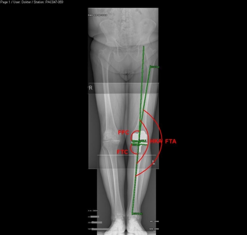
The pre- and postoperative mechanical axis (HKA), the frontal femoral component angle (FFC), and the frontal tibial component angle (FTC) were measured and are depicted in Fig. 1. The aim of the surgery was to achieve an HKA angle of 180°. In the coronal plane, the medial angle of the components to the mechanical axes should be 90° for the tibial and femoral component.
Fig. 1.
Radiograph showing the measured angles in the coronal plane. Depicting the angle between the femoral and mechanical axis (the hip knee angle [HKA]), the angle between the anatomical femoral and tibial axis (the femoral tibial angle [FTA]), the angle between the tangent to the most distal part of the femoral condyles and the mechanical axis (the frontal femoral component angle [FFC]), and the angle between the tangent to the tibial base plate and the mechanical axis (the frontal tibial component angle [FTC])
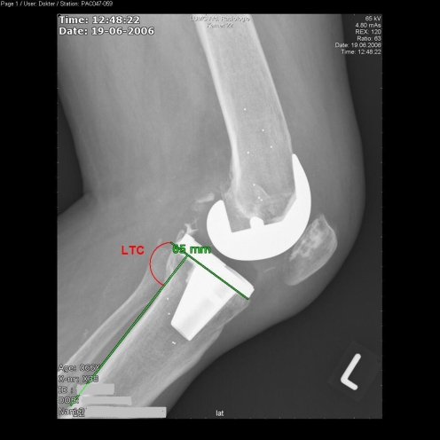
On the lateral radiographs, the lateral tibial component angle (LTC) was measured, as depicted in Fig. 2. The LTC was determined by measuring the posterior angle between a line parallel to the posterior cortex of the tibia and a line parallel to the tibial base plate. The tibia slope (TS) is expressed as 90° minus the LTC; the target of this angle was 7° as advised by the manufacturer. All of these radiographs were checked for the appearance of radiolucent lines.
Fig. 2.
Radiograph depicting the measured angle in the sagittal plane between the tangent to the tibial base plate and the tangent to the posterior cortex of the tibia (the lateral tibial component angle [LTC])
Clinical (knee society score [KSS]) and radiological evaluations were performed preoperatively, within one week postoperatively, at six weeks, three months, six months, one year, and two years postoperatively. RSA analysis was performed using the Model Based RSA (MBRSA) (version 3.02, Medis Specials, Leiden, The Netherlands) technique [14, 27]. The analogue stereo radiographs were scanned with a Vidar VXR-12 scanner (Vidar, Lund, Sweden) at a resolution of 150 dots per inch.
The x axis represents the medio–lateral axis (lateral movement taken as positive), the y axis the caudal–cranial axis (cranial movement taken as positive), and the z axis the posterior–anterior axis (anterior movement taken as positive). Translations of the centre point of the tibia are presented. The error in migration calculation with MBRSA was measured using 44 double examinations and, presented as standard deviations, is 0.06 mm for translations in the x and y directions and 0.16 mm for the out of plane z direction. For rotations about the y axis, the standard deviation was 0.3° and for rotations about the x and z axis 0.2°. Since migration is highly dependent on the type of implant, only the fluted fixed based tibial components were analysed for micromotion (11 CT-free CAOS, 9 CT-based CAOS, and 19 conventional TK).
Statistical methods
The statistical analysis was performed using the statistical software package SPSS (version 12.0.1, SPSS Inc., Chicago, USA). Mean values and standard deviations of the measured angles and the clinical scores were calculated for each group. A one-way ANOVA was used on the data to determine the differences between the three groups with respect to the continuous variables. A Levene’s test was used to determine whether the group variances were equal for the tested parameters. If the variances were unequal a Kruskal-Wallis test was used instead of a one-way ANOVA. To determine the effect of deviation from the ideal HKA on micromotion, the radiographic angle measurements were categorised: well aligned (within 3° deviation of the ideal positioning) and mal-aligned (more than 3° deviation from the ideal positioning). The chi-square test was used to analyse the categorical data. The Pearson’s correlation test was used to detect any correlation between micromotion and component alignment.
Results
Radiographic results
Hip knee ankle angle
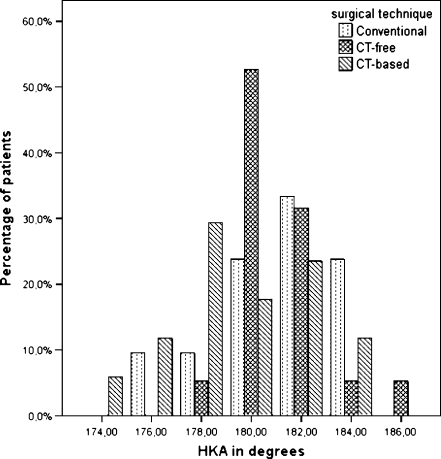
No significant difference was found between the three TK groups (Fig. 3, chi-squared p = 0.2) with respect to deviation from ideal alignment. While the CT-based CAOS group had more valgus malaligned knees (mean 179°, SD 3.0°), the conventional group had more varus malaligned knees (mean 181°, SD 2.7°), as can be seen in Fig. 3. The CT-free CAOS group (mean 181°, SD 1.9°) showed the least variance (Levene’s test p = 0.07), but no significant difference was seen between the mean of the three groups (ANOVA p = 0.07) (see Table 1 and Fig. 3).
Fig. 3.
Chart depicting the distribution of the hip knee angle (HKA) for the three groups of surgical technique. No significant difference was found between the three groups (chi-squared p = 0.2)
Table 1.
Number of TK aligned within the ideal range (within 3°) for the different limb and component angles
| Angle (°) | Desired range (°) | Conventional | CT-free | CT-based | P value |
|---|---|---|---|---|---|
| (n = 21) | (n = 19) | (n = 17) | |||
| HKA | 177–183 | ||||
| Mean (SD) | 181 (2.7) | 181 (1.9) | 179 (3.0) | 0.07 | |
| Within range (n) | 14 | 17 | 12 | 0.2 | |
| FTA | |||||
| Mean (SD) | 175 (2.8) | 176 (2.7) | 174 (3.6) | 0.3 | |
| FTC | 87–93 | ||||
| Mean (SD) | 89 (2.4) | 89 (1.5) | 89 (1.7) | 0.8 | |
| Within range (n) | 20 | 18 | 16 | 1.0 | |
| FFC | 87–93 | ||||
| Mean (SD) | 90 (1.8) | 90 (1.3) | 91 (2.8) | 0.6 | |
| Within range (n) | 20 | 19 | 13 | 0.03 | |
| TS | 4–10 | ||||
| Mean (SD) | 5.4 (3.8) | 5.0 (2.9) | 5.2 (2.6) | 0.9 | |
| Within range (n) | 12 | 14 | 13 | 0.4 | |
HKA hip knee angle, FTA femoral tibial angle, FTC frontal tibial component angle, FFC frontal femoral component angle, TS tibial slope
Frontal component angles
With respect to alignment, the tibial implants were all very well aligned (chi-squared p = 1.0) (see Table 1 and Fig. 4).
Fig. 4.
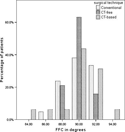
Chart depicting the distribution of the frontal femoral component angle (FFC) for the three surgical technique groups. The CT-free group had significantly more well aligned components than the CT-based group (chi-squared p = 0.03)
With regard to the femoral implants, the conventional group had 20 out of 21 well aligned knees, the CT-free CAOS group had all 19 out of 19 knees well aligned, and the CT-based had 13 out of 17 well aligned knees. This difference was significant (chi-squared p = 0.03).
Tibial slope
A satisfactory slope within 3° of the optimum was achieved in 12 of the 21 implants in the conventional group, 14 of the 19 implants in the CT-free CAOS group, and in 13 of the 17 implants in the CT-based CAOS group. These differences were not significant (p = 0.4) (Table 1).
RSA results
Translations
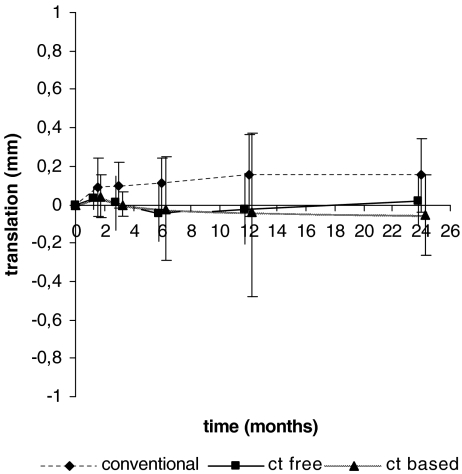
At six months follow-up, the mean migration along the y axis (i.e. subsidence) of the tibial component was 0.08 mm (SD 0.089) for the conventional group, −0.033 mm (SD 0.144) for the CT-free group, and −0.035 mm (SD 0.259) for the CT-based group. At one year follow-up these values were 0.12 mm (SD 0.193) for the conventional group mean, −0.014 mm (SD 0.189) for the CT-free group mean, and −0.028 mm (SD 0.408) for the CT-based group mean (see Fig. 5). These differences were not significant (ANOVA p = 0.1 and ANOVA p = 0.2, respectively) between the groups.
Fig. 5.
Graph depicting the migration along the caudal–cranial axis (subsidence). The values are given as mean and standard deviation and are positive if the translation was in the cranial direction. Significantly more micromotion was seen in the conventional group
At two-year follow-up, a significant difference was present (ANOVA p = 0.01) for micromotion along the caudal–cranial y axis (i.e. subsidence), with the conventional TK group showing more micromotion (mean 0.16 mm, SD 0.191 mm) compared to the CT-free group (mean 0.01 mm, SD 0.123 mm) and the CT-based group (mean −0.05 mm SD 0.208 mm) (Table 2, Fig. 5). The CT-based group showed more variance (Levene’s test p = 0.04) with a large variation in translation in the posterior–anterior z axis.
Table 2.
Mean translations (95% confidence interval) and mean rotations (95% confidence interval) of the tibial component at two-year follow-up
| Direction | Conventional n = 19 | CT-free n = 11 | CT-based n = 9 | P value | |
|---|---|---|---|---|---|
| Translation (mm) | Lateral–medial | 0.04 (−0.057, 0.142) | 0.07 (−0.039, 0.173) | 0.04 (−0.182, 0.259) | 0.9 |
| Caudal–cranial | 0.16 (0.065, 0.250) | 0.01 (−0.069, 0.097) | −0.05 (−0.213, 0.107) | 0.01 | |
| Posterior–anterior | −0.14 (−0.371, 0.099.) | −0.02 (−0.256, 0.217) | 0.43 (−0.822, 1.680) | 0.3 | |
| Rotation (°) | Anterior tilt | 0.02 (−0.370, 0.403) | −0.02 (−0.654, 0.608) | 0.67 (−1.055, 2.398) | 0.4 |
| Internal rotation | −0.14 (−0.442, 0.171) | −0.30 (−0.790, 0.186) | 0.05 (−1.057, 1.163) | 0.7 | |
| Lateral tilt | −0.09 (−0.268, 0.095) | −0.17 (−0.421, 0.086) | −0.18 (−0.507, 0.142) | 0.8 |
Rotations
The mean rotations along the three axes were not significantly different between the three groups. No correlation with any of the measured angles (e.g. HKA, FFC, LTC, and FTC) was found.
There was one outlier in each group. They showed large migrations in the posterior–anterior direction (conventional 1.20 mm, CT-free 1.38 mm, and CT-based 1.00 mm) and anterior tilting (1.82°, 2.66°, and 2.08°, respectively). One of these patients (CT-based, BMI 30 kg/m2) had a broken tibial cam and the implant had to be revised. This caused the large SD in this group. Migration of the tibial component from a patient of the CT-free group seemed to stabilise during the follow-up, another migrating tibial component from the conventional group showed continuous micromotion during the study follow-up. Neither were severely obese (BMI = 26 kg/m2 and 27 kg/m2 respectively) but were outliers with respect to the HKA and FTA. The patient showing the continuous migration had a varus malalignment of 6°, while the other patient was 4° with respect to the HKA.
Clinical results
In the clinical evaluations no differences were seen between the three groups in postoperative knee society score. The knee society scores and the flexion and extension of the knee are listed in Table 3.
Table 3.
Postoperative clinical scores at one-year follow-up (mean [SD])
| Parameter evaluated | Conventional (n = 21) | CT-free (n = 17) | CT-based (n = 15) | P value |
|---|---|---|---|---|
| KSS knee | 65 (13.8) | 66 (17.6) | 61 (6.7) | 0.6 |
| KSS function | 66 (33.5) | 80 (16.9) | 70 (23.1) | 0.5 |
| Flexion (°) | 116 (11.4) | 117 (12.6) | 115 (11.9) | 1.0 |
| Extension (°) | −1 (7.5) | −3.4 (6.5) | −1 (6.8) | 0.8 |
The mean surgical time was 137 (SD 43.3) minutes in the conventional group, 148 (SD 25.0) minutes in the CT-free CAOS group, and 159 (SD 33.3) minutes in the CT-based group (Kruskal-Wallis p = 0.1).
Discussion
The necessity to align the limb correctly after total knee arthroplasty has been stressed by others [1, 10, 22, 25]. Malpositioning in any of the anatomical planes of the knee can cause problems such as early loosening and excessive polyethylene wear. The aim should be a restoration of the mechanical axis of the leg (HKA of 180°) where a valgus malalignment is more forgiving than a varus malalignment [1, 22]. To optimise TK placement CAOS has been promoted. After it’s introduction several authors noted significant improvement in prosthesis position with CAOS compared to the conventional technique with alignment guides [1–4, 5, 7, 11, 17, 19, 20]. At present, no long-term results in comparison to conventionally placed TK are available. Continuous micromotion during the first two postoperative years is a warning for probable aseptic loosening at ten years [23]. Thus, RSA micromotion measurements will relate best to the value of a new CAOS technique for knee prosthesis placement with respect to longevity of the implant [23]. This study compared two CAOS techniques to the conventional method of TK replacement. Only four studies have used a CT-based CAOS technique and compared it to the conventional technique [1, 3, 11, 20].
We were unable to perform a sample size calculation because the expected proportion of micromotion of the navigated TK was unknown due to lack of previous studies.
Since TK malalignment is considered a key factor for excessive TK micromotion with consequent failure at late follow-up, the overall alignment (i.e. HKA) in the three groups was within one degree of the ideal alignment. Ideal alignment of the tibial component in the sagittal plane was present in only 57% of the conventional TK and 74–76% in the two CAOS TK groups. Since the study’s population was small and inaccuracy of radiographs is rather high [9], data from our study might not have reached significance.
The mean caudal–cranial translation of the “conventional” tibial component was clinically small (0.16 mm) at two-year follow-up, but it was significantly larger than in the two CAOS groups. As early migration of this component is considered to be predictive for early loosening, this value indicates that in the long run the “conventional” tibial component might perform worse than the two “CAOS” components in terms of early loosening.
This study showed a significantly better alignment (p = 0.03) in the FFC for the CT-free compared to the CT-based group. Although the difference of one degree was clinically not relevant, this result is similar to the study of Matziolis et al. in which the alignment of the femoral component was improved by CT-free CAOS [21]. The comparison in other outcome measures between CT-free and CT-based CAOS showed similar results to the study of Bathis et al., with no significant difference but a better performance of CT-free CAOS [1].
A potential error in CT-based CAOS originates during the preoperative planning, where detection of the border of bone is dependent on the settings of the threshold of the grey values. Therefore visualisation of severely damaged bone is extremely difficult. Ironically, these severely damaged knees are the ones one would like to be able to plan in advance because of their potential difficulty during surgery.
The mean duration of the surgical procedure was prolonged as well, with the CT-free procedure lasting nine minutes and the CT-based procedure 22 minutes longer. Though no significant difference existed, this could potentially lead to a higher infection rate. Another disadvantage is the additional radiation dose because of the preoperative CT-scan.
In both techniques the same reference trees are attached to the femur and tibia. No complications of these markers were seen pre- or postoperatively so far. However, there are some case reports describing a femoral stress fracture related to the hole of the reference tree [12, 16].
In this study a significant difference in micromotion in caudal–cranial direction between the groups at two years was found, with more micromotion in the conventional group. CT-free CAOS showed a significantly better performance in FFC than CT-based CAOS, though clinically similar results for limb and TK alignment were found.
Acknowledgments
Open Access
This article is distributed under the terms of the Creative Commons Attribution Noncommercial License which permits any noncommercial use, distribution, and reproduction in any medium, provided the original author(s) and source are credited.
References
- 1.Bargren JH, Bhaha JD, Freeman MAR. Alignment in total knee arthroplasty: correlated biomechanical and clinical observations. Clin Orthop Relat Res 83. 1983;173:178–183. [PubMed] [Google Scholar]
- 2.Bäthis H, Perlick L, Tingart M, Lüring C, Zurakowski D, Grifka J. Alignment in total knee arthroplasty; a comparison of computer-assisted surgery with the conventional technique. J Bone and Joint Surg. 2004;86-B:682–687. doi: 10.1302/0301-620X.86B5.14927. [DOI] [PubMed] [Google Scholar]
- 3.Bäthis H, Perlick L, Tingart M, Lüring C, Perlick C, Grifka J. Radiological results of CT-based and non-CT-based total knee arthroplasty. Int Orthop. 2004;28:87–90. doi: 10.1007/s00264-003-0533-y. [DOI] [PMC free article] [PubMed] [Google Scholar]
- 4.Bejek Z, Sólyom L, Szendrõi M. Experiences with computer navigated total knee arthroplasty. Int Orthop. 2007;31:617–622. doi: 10.1007/s00264-006-0254-0. [DOI] [PMC free article] [PubMed] [Google Scholar]
- 5.Chin PL, Yang KY, Yeo SJ, Lo NN. Randomized control trial comparing radiographic total knee arthroplasty implant placement using computer navigation versus conventional technique. J Arthroplasty. 2005;20(5):618–626. doi: 10.1016/j.arth.2005.04.004. [DOI] [PubMed] [Google Scholar]
- 6.Decking R, Markmann Y, Fuchs J, Wolfhart P, Scharf H. Leg axis after computer-navigated total knee arthroplasty: a prospective randomized trial comparing computer-navigated and manual implantation. J Arthroplasty. 2005;20(3):282–288. doi: 10.1016/j.arth.2004.09.047. [DOI] [PubMed] [Google Scholar]
- 7.Haaker RG, Stockheim M, Kamp M, Proff G, Breitenfelder J, Ottersbach A. Computer-assisted navigation increases precision of component placement in total knee arthroplasty. Clin Orthop Relat Res. 2005;443:152–159. doi: 10.1097/01.blo.0000150564.31880.c4. [DOI] [PubMed] [Google Scholar]
- 8.Insall JN, Dorr LD, Scott RD, Scott WN. Rationale of the knee society clinical rating system. Clin Orthop Relat Res. 1989;248:13–14. [PubMed] [Google Scholar]
- 9.Ivarsson I, Myrnerts R. The effect of the radiographic projection on the measured position of the prosthesis at knee arthroplasty. Arch Orthop Trauma Surg. 1986;105:350–352. doi: 10.1007/BF00449941. [DOI] [PubMed] [Google Scholar]
- 10.Jeffery RS, Morris RW, Denham RA. Coronal alignment after total knee replacement. J Bone Joint Surg. 1991;73-B:709–714. doi: 10.1302/0301-620X.73B5.1894655. [DOI] [PubMed] [Google Scholar]
- 11.Jenny J, Boeri C. Computer-assisted implantation of total knee prosthesis: a CAOS control comparative study with classical instrumentation. Computer Aided Surg. 2001;6:217–220. doi: 10.3109/10929080109146086. [DOI] [PubMed] [Google Scholar]
- 12.Jung HJ, Jung YB, Song KS, Park SJ, Lee JS. Fractures associated with computer-navigated total knee arthroplasty. A report of two cases. J Bone Joint Surg Am. 2007;89(10):2280–2284. doi: 10.2106/JBJS.F.01166. [DOI] [PubMed] [Google Scholar]
- 13.Lüring C, Bäthis H, Tingart M, Perlick L, Grifka J. Computer assistance in total knee replacement: a critical assessment of current health care technology. Computer Aided Surg. 2006;11(2):77–80. doi: 10.1080/10929080600578925. [DOI] [PubMed] [Google Scholar]
- 14.Kaptein BL, Valstar ER, Stoel BC, Reiber HC, Nelissen RG. Clinical validation of model-based RSA for a total knee prosthesis. Clin Orthop Relat Res. 2007;464:205–209. [PubMed] [Google Scholar]
- 15.Kellgren JH, Lawrence JS. Radiological assessment of osteoarthritis. Ann Rheum Dis. 1957;16(4):485–493. doi: 10.1136/ard.16.4.485. [DOI] [PMC free article] [PubMed] [Google Scholar]
- 16.Li CH, Chen TH, Su YP, Shao PC, Lee KS, Chen WM. Periprosthetic femoral supracondylar fracture after total knee arthroplasty with navigation system. J Arthroplasty. 2008;23(2):304–307. doi: 10.1016/j.arth.2006.12.049. [DOI] [PubMed] [Google Scholar]
- 17.Maculé-Beneyto F, Hernández-Vaquero D, Segur-Vilalta JM, Colomina-Rodriguez R, Hinarejos-Gomez P, Garcia-Forcada I, Seral Garcia B. Navigation in total knee arthroplasty. A multicenter study. Int Orthop. 2006;30:536–540. doi: 10.1007/s00264-006-0126-7. [DOI] [PMC free article] [PubMed] [Google Scholar]
- 18.Mahaluxmivala J, Bankes MJK, Nicolai P, Aldam CH, Allen PW. The effect of surgeon experience on component positioning in 673 press fit condylar posterior cruciate sacrificing total knee arthroplasties. J Arthroplasty. 2001;16(5):635–640. doi: 10.1054/arth.2001.23569. [DOI] [PubMed] [Google Scholar]
- 19.Malik MHA, Wadia F, Porter ML. Preliminary radiological evaluation of the vector vision CT-free knee module for implantation of the LCS knee prosthesis. The Knee. 2007;24:19–21. doi: 10.1016/j.knee.2006.10.001. [DOI] [PubMed] [Google Scholar]
- 20.Martin A, von Strempel A. Two-year outcomes of computed tomography-based and computed tomography free navigation in total knee arthroplasties. Clin Orthop Relat Res. 2006;449:275–282. doi: 10.1097/01.blo.0000218738.69247.d8. [DOI] [PubMed] [Google Scholar]
- 21.Matziolis G, Krocker D, Weis U, Tohtz S, Perka C. A prospective, randomized study of computer-assisted and conventional total knee arthroplasty. Three-dimensional evaluation of implant alignment and rotation. J Bone Joint Surg Am. 2007;89:236–243. doi: 10.2106/JBJS.F.00386. [DOI] [PubMed] [Google Scholar]
- 22.Ritter MA, Faris PM, Keating EM, Meding JB. Postoperative alignment of total knee replacement: its effect on survival. Clin Orthop Relat Res. 1994;299:153–156. [PubMed] [Google Scholar]
- 23.Ryd L, Albrektsson BEJ, Carlsson L, Dansgård F, Herberts P, Lindstrand A, Regnér L, Toksvig-Larsen S. Roentgen stereophotogrammetric analysis as a predictor of mechanical loosening of knee prosthesis. J Bone Joint Surg. 1995;77-B:377–383. [PubMed] [Google Scholar]
- 24.Sparmann M, Wolke B, Czupalla H, Banzer D, Zink A. Positioning of total knee arthroplasty with and without navigation support. J Bone Joint Surg. 2003;85-B(6):830–835. [PubMed] [Google Scholar]
- 25.Tew M, Waugh W. Tibiofemoral alignment and the results of knee replacement. J Bone and Joint Surg. 1985;67-B(4):551–556. doi: 10.1302/0301-620X.67B4.4030849. [DOI] [PubMed] [Google Scholar]
- 26.Valstar ER, Nelissen RGHH, Reiber JHC, Rozing PM. The use of roentgen stereophotogrammetry to study micromotion of orthopaedic implants. ISPRS J Photogramm. 2002;56:376–389. doi: 10.1016/S0924-2716(02)00064-3. [DOI] [Google Scholar]
- 27.Valstar ER, de Jong FW, Vrooman HA, Rozing PM, Reiber JH. Model-based roentgen stereophotogrammetry of orthopaedic implants. J Biomech. 2001;34(6):715–722. doi: 10.1016/S0021-9290(01)00028-8. [DOI] [PubMed] [Google Scholar]


