Abstract
The goal of non-fusion stabilization is to reduce the mobility of the spine segment to less than that of the intact spine specimen, while retaining some residual motion. Several in vitro studies have been conducted on a dynamic system currently available for clinical use (Dynesys®). Under pure moment loading, a dependency of the biomechanical performance on spacer length has been demonstrated; this variability in implant properties is removed with a modular concept incorporating a discrete flexible element. An in vitro study was performed to compare the kinematic and stabilizing properties of a modular dynamic lumbar stabilization system with those of Dynesys, under the influence of an axial preload. Six human cadaver spine specimens (L1–S1) were tested in a spine loading apparatus. Flexibility measurements were performed by applying pure bending moments of 8 Nm, about each of the three principal anatomical axes, with a simultaneously applied axial preload of 400 N. Specimens were tested intact, and following creation of a defect at L3–L4, with the Dynesys implant, with the modular implant and, after removal of the hardware, the injury state. Segmental range of motion (ROM) was reduced for flexion–extension and lateral bending with both implants. Motion in flexion was reduced to less than 20% of the intact level, in extension to approximately 40% and in lateral bending a motion reduction to less than 40% was measured. In torsion, the total ROM was not significantly different from that of the intact level. The expectations for a flexible posterior stabilizing implant are not fulfilled. The assumption that a device which is particularly compliant in bending allows substantial intersegmental motion cannot be fully supported when one considers that such devices are placed at a location far removed from the natural rotation center of the intervertebral joint.
Keywords: Dynamic posterior stabilization, Dynesys, Biomechanics, In vitro testing, Axial preload
Introduction
Lifetime incidence of low back pain is estimated at 70–85% [1, 15]. Consequently, the number of surgeries performed for low back pain is constantly increasing. In addition to the underlying effects of an aging population, changes including the paradoxical increase in obesity and the elevated leisure time activity level of many place ever-higher demands on treatment solutions. One of the standard surgical interventions for chronic low back pain, which aims to eliminate motion at the joint, is spinal fusion. It has been shown that this treatment is more effective than conservative care [8]. However, one major concern remains the potential for accelerated disc degeneration adjacent to the fused segments. There are a few clinical studies reporting so-called “adjacent segment disease”. In one study [23] it appeared in only a few cases, while in others disc degeneration in the adjacent segments has been reported in more than 40% of the patients [6, 11, 12, 20]. For younger patients, there is a desire to avoid or at least delay a fusion procedure. An attractive alternative is a dynamic non-fusion system, which aims to maintain the mobility of the motion segment while preventing negative effects at the adjacent segments. There are different systems available for this purpose, ranging from the complete replacement of the intervertebral disc with a prosthesis [13, 14] to devices, which preserve the disc as well as the facet joints, but provide a “dynamic neutralization”, which was conceived to limit and guide segmental motion to a physiological range.
In the category of dynamic neutralization systems, the Dynesys® (Zimmer GmbH, Winterthur, Switzerland) is arguably the most popular embodiment of this philosophy [7, 24]. It has been shown in a multicenter study, that the Dynesys system is a safe and effective procedure for the stabilization of the lumbar spine [24]. This system is a bilateral posterior device, which consists of titanium alloy pedicle screws and polycarbonate urethane (PCU) spacers that surround tensioned polyethylene terephalate (PET) cords. To withstand compression forces, which occur during extension movements, the PCU spacers are placed bilaterally between the pedicle screw heads. Tensile forces, which act during flexion movements are stabilized by the pre-tensioned PET cords, which run through the hollow core of the PCU spacers. A standardized preload of 300 N is applied to the cord during implantation; however, the length of the spacer, which has to be adjusted to match each patient, directly influences lordosis, the intersegmental motion and loading [16].
This trend toward dynamic neutralization systems requires an evolution of implant design to address the potential shortcomings of current devices. In this study, a new concept for dynamic posterior spinal stabilization has been evaluated. The functional intent of this prototype implant is also to preserve segmental mobility, while distracting the segment and limiting the extents of motion to reduce the loading at the facet joints. Similar to the Dynesys, this device concept is intended for bilateral implantation, using transpedicular screws, but comprises rigid metal rods, which incorporate discrete flexible PCU elements, with fixed properties: the intersegmental rod length therefore does not influence the bending stiffness.
The aim of the study was to quantitatively compare the kinematics and stabilizing properties of this modular dynamic lumbar stabilization concept with those of a dynamic system currently available on the market for clinical use (Dynesys), under the influence of a simulated physiological preload. The hypotheses tested in this study were: (1) that the creation of a controlled defect in the intact spine has a significant destabilizing effect despite a superimposed axial follower load, and (2) the modular dynamic lumbar stabilization system provides stability by reducing the mobility of the destabilized spine segment to less than that of the intact spine specimen in all three principal planes, while preserving some degree of residual motion.
Materials and methods
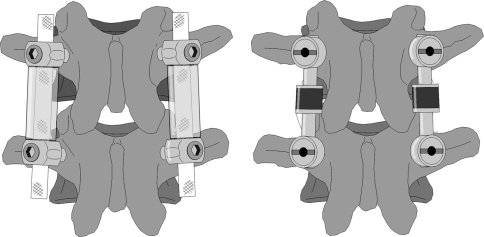
In contrast to the Dynesys, the flexible posterior structure of the modular device (Synthes GmbH, Oberdorf, Switzerland) consists of a fixed length metallic rod with an integrated polymeric (PCU) damping unit, joined to a second metallic rod, which can be trimmed to length. The two rod components are assembled via a form-fitting, locking connection at the damper unit to form a single continuous element, of variable length but with a pre-defined bending stiffness. The connection of the flexible rod element to the pedicle screws is accomplished using poly-axial screw heads to ensure alignment (Fig. 1).
Fig. 1.
Illustration of Dynesys® (left) and of the modular dynamic stabilization system (right)
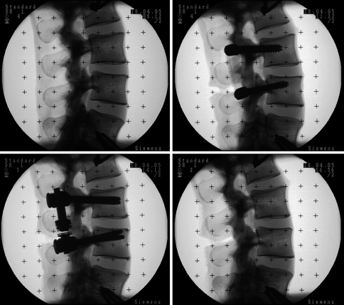
Six human cadaveric lumbar spine specimens (L1–S1) from random donors (average age 72.8 years, range 67–79) were used for the biomechanical testing. Following harvesting, all surrounding soft tissues were removed, preserving the ligamentous structures. The specimens were stored in vacuum-sealed polyethylene bags at −20°C until the day before testing and then thawed at room temperature overnight before testing. Frozen storage has been shown to have a minimal influence on the segmental biomechanics of spine specimens [5, 18]. The trabecular volumetric bone mineral density was measured using a Densiscan 1000 peripheral quantitative CT machine (Scanco Medical, Dübendorf, Switzerland) and specimens were screened to preclude osteoporosis or other degenerative bone diseases. The specimens had an average trabecular bone mineral density of 0.173 ± 0.085 g/cm3. Fluoroscopic C-arm images of all spine specimens were taken in the anterior–posterior and lateral projections (Fig. 2). In order to fix the specimens in the spine testing apparatus, the cranial and caudal vertebrae (L1 and S1) were embedded in polymethylmethacrylate (PMMA) cement, using a custom potting jig to align the L3–L4 disc horizontally and preserve one fully mobile disc above and below the segment of interest. Wood screw fixation, extending partially into L2 and L5, was used to enhance the connection between the embedding material and the specimen.
Fig. 2.
Fluoroscopic C-arm images in the lateral projection, intact (top left), Dynesys® (top right), modular dynamic stabilization system (bottom left), injury (bottom right)
Recommendations have been made in the literature on mechanical testing protocols. Panjabi [17] and Wilke et al. [27] have proposed the use of flexibility tests, as no artificial constraints are applied to the specimen’s motion, and a reproducible pure moment of known magnitude can be applied over the whole specimen throughout the entire test. The addition of a compressive axial preload to the standard flexibility protocol, directed along the neutral axis of the spine, is a further refinement toward a more “physiological”, but still reproducible, loading for in vitro testing [19, 25]. This “follower load” simulates torso mass and spinal muscle activity.
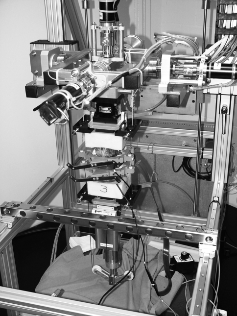
Non-destructive flexibility tests were performed in a custom-built dynamic spine testing apparatus (Fig. 3), which uses orthogonally-mounted electric motors in a cardan frame to apply pure moments (±0.1 Nm) about the three principal testing axes, while the specimen is allowed to move in an unconstrained three-dimensional fashion [9]. A standardized flexibility test was conducted, which consisted of applying monotonic pure moments of flexion–extension, bilateral lateral bending and torsion individually to a maximum of 8 Nm for three complete cycles. The specimens were tested in all directions with a constant angular displacement rate of 0.8°/s, which is in accordance with the proposed loading rates [26]. All the tests were conducted with a 400-N compressive axial preload applied via guided cables. The effects of the placement of the cable guides have been previously investigated by Cripton et al. [3]. The follower load path was optimized in such a way that the application of the compressive axial preload did not create any rotations while all six degrees of freedom of the spine testing apparatus were unconstrained, with the spine in the neutral position.
Fig. 3.
Custom-built dynamic spine testing apparatus. Each vertebra is surrounded by a follower-load guide, which allows the precise placement of the cables for load application and also provides a base for optoelectronic motion capture markers. A heating tape was wrapped around the disc and posterior elements to ensure that the PCU components of the implant were at 37°C during testing
The follower load setup consists of individual frames, which can be fixed rigidly to each vertebral body. Each frame is attached anteriorly by screws inserted into the vertebral cortex through two integral drill guidance sleeves and posteriorly by a serrated plate clamped against the spinous process by a threaded thumbscrew. Guide plates were attached as well to the cranial and caudal PMMA blocks. These frames and plates are equipped with adjustable Teflon cable sleeves in spherical bearings, which ensure self-alignment of the cable path. The follower load cable was fixed laterally on both sides above the load cell, passed through the Teflon sleeves and over a bearing pulley system attached to a pneumatic cylinder, which applied a balanced compressive load to both sides of the specimen, independent of specimen motion in all planes.
In a pilot study with two intact specimens, the influence of the follower load setup on specimen kinematics was evaluated. Changes in range of motion (ROM), compared to the tests with no preload, were −13.3 and −6.1% in flexion–extension and −8.4 and +1.7% in lateral bending. In torsion, the total ROM decreased by 63.2 and 73.9%. Part of this decrease may be explained by a natural stiffening of the spine under preload, but likely a large part comes from a stiffening effect of the follower load setup in torsion.
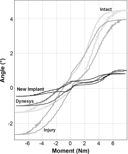
A six-axis load cell (MC3A, AMTI, Watertown, MA, USA) at the cranial end of the specimen recorded all the moments and forces acting on the specimen. For motion analysis, sets of four light emitting diodes (LEDs) were attached rigidly to the follower load frames of the L3 and the L4 vertebral bodies, which in turn were attached rigidly to the vertebral bodies. The spatial positions of the LEDs were tracked by an optoelectronic camera (Optotrak 3020, Northern Digital, Waterloo, ON, Canada) and were recorded continuously during the tests. The relative three-dimensional rotations of the vertebral pair of interest (L3–L4) were calculated. For each applied moment and for all testing configurations, the ROM and the neutral zone (NZ), which defines the laxity in the spine flexibility curve about the zero moment crossing points, were calculated on the basis of flexibility curves (Fig. 4).
Fig. 4.
Example of flexibility curves in flexion–extension of the intact specimen, the injured specimen instrumented with Dynesys, the injured specimen instrumented with the new modular implant and the injured specimen
Biomechanical testing was first performed with the intact specimen, then following injury creation and single-level instrumentation with the Dynesys implant (L3–L4), single-level instrumentation with the modular dynamic lumbar stabilization system using the same screw holes, and finally, after removal of the hardware, the injury case was tested. The unstabilized injury case was tested last in the sequence to prevent damage to the specimen. The injury consisted of a controlled defect: complete sectioning of the ligamenta supraspinous, ligamenta interspinous, ligamenta flavum, sectioning of the joint capsules and partial nucleotomy (approximately 25%) [21]. The larger thread diameter and greater screw length of the modular system were sufficiently larger than those of Dynesys (Ø6.2 × 45 vs. Ø6.0 × 40 mm) to allow reuse of the same mounting holes. No screw loosening was observed during testing.
Both dynamic neutralization systems consist of components manufactured from PCU, which varies its stiffness with temperature. To simulate body temperature (37°C) a flexible heating tape with an integrated controller (Brisk Heat, BH Thermal Corporation, Columbus, OH, USA) was used. This heating tape was wrapped around the disc and implants and fixed together behind the spinous process. The gap between the implants and the posterior elements of the functional spine unit was filled with saline-soaked gauze to ensure a good heat flow between the heating tape and the implants. The implant temperature was verified before each test with a digital contact thermometer. Both implants were placed by a surgeon according to the manufacturer’s recommended procedure. After measuring the vertical distance between opposing pedicle screw heads in the neutral posture, the Dynesys spacers were cut 2 mm longer to distract the spine segment. The average spacer length was 27.5 ± 5.4 and 30.1 ± 3.4 mm on the left and right sides, respectively. Variations in the angle of the screws in relation to the vertical axis resulted in differences in the lengths of the spacers on each side. With the help of a spinal distractor, the same intersegmental distraction was set for the modular implant prior to tightening the polyaxial screw heads.
A repeated-measures analysis of variance (ANOVA) was performed to test for significant differences in the calculated ROM and NZ for the sequentially performed tests. Prior to analysis, the normal distribution of the data was verified (normal p–p plots) and the use of the ANOVA was justified. Differences between individual testing conditions were evaluated with a Tukey’s post-hoc analysis. A significance level of P = 0.05 was defined and all statistical analyses were performed using Statistica 8.0 (StatSoft, Inc.).
Results
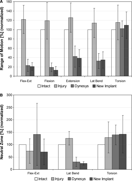
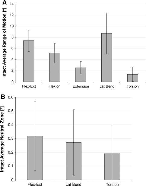
The kinematic results presented in Fig. 5 are normalized to the intact motion magnitudes, which are shown in absolute values (degrees) in Fig. 6. Despite the creation of a substantial simulated injury, differences in segmental ROM in all principal motion directions for the injury case, compared to the intact specimen, were not significant.
Fig. 5.
a L3–L4 segmental range of motion normalized to intact motion magnitude. b L3–L4 segmental neutral zone normalized to intact motion magnitude
Fig. 6.
a L3–L4 segmental range of motion in (°) for intact conditions. b L3–L4 segmental neutral zone in (°) for intact conditions
Following instrumentation with dynamic stabilization implants, segmental ROM was significantly reduced for flexion–extension and lateral bending with both the Dynesys and the modular implant (P < 0.001). On average, motion in flexion was reduced to less than 20% of the intact level, and in extension to approximately 40% of the intact level. In lateral bending, a motion reduction to less than 40% of the intact level was measured. In torsion, the total ROM was not significantly different than that of the intact level. No significant differences were found between the two implant types for total ROM (flexion–extension, P = 0.89; lateral bending, P = 0.98, torsion, P = 0.56).
A large variability was observed in the changes to the segmental NZ, especially in flexion–extension. No differences were found between implant types for flexion–extension (P = 0.39), lateral bending (P = 0.99) and torsion (P = 0.43). The only notable trend was a significant reduction (P = 0.048) in the NZ for lateral bending with both implant types, compared to the injury case, although this represents an absolute change of only 0.1°–0.2°.
Discussion
The present study compared the stabilizing effect of a modular dynamic neutralization system with a system currently available on the market for clinical use (Dynesys). In the present study, an axial follower preload was included in the flexibility testing protocol, not only for flexion–extension, but also for lateral bending and torsion. In most previous in vitro studies, with the exception of the recent study by Niosi et al. [16], the follower load concept has been used only statically or during flexion–extension [19, 25]. A further refinement of the current study was the use of the original PCU spacers or damping elements, in combination with a heating tape to mimic body temperature, instead of using custom made spacers with a modified stiffness for testing at room temperature, as was done in previous studies [16, 21, 22].
It is noteworthy that the degree of stabilization observed in the present study exceeds that measured in previous in vitro testing of dynamic stabilization systems by Schmoelz et al. [21]. However, it should also be noted that, when one summarizes in vitro and in vivo results to date for the Dynesys [2, 7, 16, 21, 22], the measured stabilization is in the range of 20–40% of the intact motion, which is similar to the results obtained in the present study. In contrast to the study of Schmoelz et al. [21], the creation of an injury resulted in only a modest and non-significant increase in segmental motion. It is likely that, in addition to variation in the donor-specific properties of the specimens, the application of an axial preload, which was not included in the study of Schmoelz et al. [21], has a net stiffening effect on the intervertebral joint and implant. Tawackoli et al. have shown that a compressive axial preload reduces segmental motion, most substantially for loads on the order of 300 N, with a much less substantial increase in stiffness for a further increase in preload to 1,000 N [25]. With the creation of a destabilization injury, that included partial nucleotomy and sectioning of the joint capsules, compression of the disc space under axial loading and a consequently more severe “blocking” of the segment are likely. In the recent study of Niosi et al. [16], the addition of an axial preload had a substantial influence on the destabilizing effect of a simulated injury. Whereas a 30–50% increase in segmental ROM was observed with injury under pure moment loading, the mobility of the injury case was reduced with an axial preload to magnitudes close to or less than the intact spine, although statistical tests were not reported for these changes. The finding of a substantial stabilizing effect of the Dynesys is also in agreement with the results of Jensen et al., who were not able to show the expected flexibility of the implant in their in vitro tests [10]. In that study, the Dynesys performed identically to a normal metallic fixator, and it was also observed that a compressive preload decreased the segmental ROM even further.
The application of a compressive preload for spinal implant testing is controversial. While the use of pure-moment testing, according to the recommendations of Wilke et al. [27], facilitates a comparison of testing results between labs, even subtle differences in machine design can significantly influence the ability to achieve pure moment loading, especially on long segments [9], and therefore one should be cautious with a direct comparison between absolute quantitative test results on different machines. The addition of a compressive preload provides an approximation of muscle forces which are likely important for the function of dynamic implants. However, Cripton et al. have demonstrated that there is a mechanical trade-off with such a preload, whereby unwanted “artifact” moments can only be prevented at the cost of induced shear forces [3]. This mechanical trade-off will depend on the method of preload application. The present follower-load apparatus uses a continuous cable-and-pulley design with individual frames rigidly fixed to each vertebral body and guide plates at the cranial and caudal PMMA blocks. This apparatus was designed as a universal system for small and large lumbar vertebrae. Therefore, the lateral distance between the load cable and the vertebral body depends on its body width; however, the distance to the sagittal midplane is fixed. One advantage in comparison to the commonly used fixed eye screw guides is the available fine adjustment of the cable trajectory to the spinal curvature, through the movable and self-aligning Teflon cable sleeves, which attempts to minimize these artifact moments effects. A preload-induced decrease in segmental ROM of approximately 10, 4 and 68% for flexion–extension, lateral bending and torsion, respectively, was observed. In comparison, Niosi et al. reported a reduction of 3, 37 and 43%, respectively, with the addition of a follower-load preload [16]. While we observed only a limited influence of the preload on lateral bending, we estimate that cable path realignment could theoretically increase the applied moment by up to 10%. Despite the limited degree of rotation, we estimate that cable path realignment in torsion may reduce the effective moment by up to 30%. Therefore, further study is required to fully evaluate the influence of compressive preload on the segmental response, and results for torsion should be interpreted with caution.
A modular implant with a pre-defined bending stiffness, which is not sensitive to the patient-specific length of the flexible elements, represents a different design philosophy to that of Dynesys, and it was expected that the performance would also differ. Furthermore, a modular implant may offer the practical advantage of a simpler and more reproducible method for achieving a desired level of segmental distraction or compression, compared to the method of implant spacer cutting and pretensioning with the Dynesys. However, this device demonstrated similar stabilizing properties to the Dynesys, with a substantial reduction of segmental motion in flexion–extension and lateral bending, drawing into question the fundamental concept of dynamic devices. It is possible that the expectations for a flexible posterior stabilizing implant are currently set too high. The belief that a device that is particularly compliant in bending would allow substantial motion cannot be fully supported when one considers that such devices are placed at a location far removed from the natural rotation center of the intervertebral joint. Neither the physical bending center of the discrete damping element nor the virtual bending center of the Dynesys spacer are aligned with that of the normal intervertebral joint. Cripton et al. have shown, in a comprehensive study of the load sharing characteristics of the instrumented spine, that only 8–10% of the bending forces created during flexion and extension are carried directly by bending of the implant [4]. The predominant mechanism for transferring bending loads in the spine (80–90%) is via a force couple between the disc and the fixator; therefore, the bending compliance of the implant would be of secondary importance to its axial stiffness. While both devices are nominally more compliant than a metallic rod, they are effectively “rigid” when one considers the requirement to substantially compress or extend these elements to allow a normal amount of intersegmental rotation. From the work of Cripton et al. [4] one can also draw the conclusion that the implants are crucially important for stabilizing the compromised spine in torsion, and this is reflected in the results of the present and previous studies of dynamic stabilization devices; neither the Dynesys nor the modular device is able to substantially limit segmental motion in torsion. While the torsion measurements in the present study must be interpreted with caution, due to the stiffening effect of the compressive preload, segmental motions in torsion equal to or greater than that of the intact spine have been also observed with Dynesys also by Schmoelz et al. [21] and Niosi et al. [16].
Conclusions
The application of an axial follower preload limits the in vitro destabilizing effect of a substantial, artificially created injury in the spinal segment and may complicate the evaluation of dynamic stabilization implants. Nevertheless, it can be concluded that the modular implant offers a substantial stabilization of the spine during flexion–extension and lateral bending, but not during torsion. However, the performance is no different than that of Dynesys, which may be considered the current benchmark for such devices, despite a fundamentally different design and underlines the point that such implants cannot be considered truly dynamic and, furthermore, do not provide stabilization in torsion.
Acknowledgments
This study was partially supported by Synthes GmbH, Oberdorf and the National Research Program NRP 53 “Muskuloskeletal Health—Chronic Pain” of the Swiss National Science Foundation (Project 405340-104681).
References
- 1.Andersson GB. Epidemiological features of chronic low-back pain. Lancet. 1999;354:581–585. doi: 10.1016/S0140-6736(99)01312-4. [DOI] [PubMed] [Google Scholar]
- 2.Beastall J, Karadimas E, Siddiqui M, et al. The Dynesys lumbar spinal stabilization system: a preliminary report on positional magnetic resonance imaging findings. Spine. 2007;32(6):685–690. doi: 10.1097/01.brs.0000257578.44134.fb. [DOI] [PubMed] [Google Scholar]
- 3.Cripton PA, Bruehlmann SB, Orr TE, et al. In vitro axial preload application during spine flexibility testing: towards reduced apparatus-related artefacts. J Biomech. 2000;33(12):1559–1568. doi: 10.1016/S0021-9290(00)00145-7. [DOI] [PubMed] [Google Scholar]
- 4.Cripton PA, Jain GM, Wittenberg RH, et al. Load-sharing characteristics of stabilized lumbar spine segments. Spine. 2000;25(2):170–179. doi: 10.1097/00007632-200001150-00006. [DOI] [PubMed] [Google Scholar]
- 5.Dhillon N, Bass E, Lotz J. Effect of frozen storage on the creep behaviour of human intervertebral discs. Spine. 2001;26(8):883–888. doi: 10.1097/00007632-200104150-00011. [DOI] [PubMed] [Google Scholar]
- 6.Eck JC, Humphreys SC, Hodges SD. Adjacent-segment degeneration after lumbar fusion: a review of clinical, biomechanical, and radiologic studies. Am J Orthop. 1999;28:336–340. [PubMed] [Google Scholar]
- 7.Freudiger S, Dubois G, Lorrain M. Dynamic neutralization of the lumbar spine confirmed on a new lumbar spine simulator in vitro. Arch Orthop Trauma Surg. 1999;119:127–132. doi: 10.1007/s004020050375. [DOI] [PubMed] [Google Scholar]
- 8.Fritzell P, Hagg O, Wessberg P, et al. Volvo award winner in clinical studies: lumbar fusion versus nonsurgical treatment for chronic low back pain: a multicenter randomized controlled trial for the Swedish Lumbar Spine Study Group. Spine. 2001;26:2521–2532. doi: 10.1097/00007632-200112010-00002. [DOI] [PubMed] [Google Scholar]
- 9.Gédet P, Thistlethwaite PA, Ferguson SJ. Minimizing errors during in vitro testing of multisegmental spine specimens: considerations for apparatus design and experimental protocol. J Biomech. 2007;40(8):1881–1885. doi: 10.1016/j.jbiomech.2006.07.024. [DOI] [PubMed] [Google Scholar]
- 10.Jensen LM, Dawson JM, Springer S et al (2004) Kinematic evaluation of non-rigid posterior stabilization. Proceedings of the 50th annual meeting of the Orthopaedic Research Society, San Francisco
- 11.Lee CK. Accelerated degeneration of the segment adjacent to a lumbar fusion. Spine. 1988;13:375–377. doi: 10.1097/00007632-198803000-00029. [DOI] [PubMed] [Google Scholar]
- 12.Lehmann TR, Spratt KF, Tozzi JE, et al. Long-term follow-up of lower lumbar fusion patients. Spine. 1987;12(2):97–104. doi: 10.1097/00007632-198703000-00004. [DOI] [PubMed] [Google Scholar]
- 13.Link HD. History, design and biomechanics of the LINK SB Charite artificial disc. Eur Spine J. 2002;11(Suppl 2):98–105. doi: 10.1007/s00586-002-0475-x. [DOI] [PMC free article] [PubMed] [Google Scholar]
- 14.Mayer HM, Wiechert K, Korge A, et al. Minimally invasive total disc replacement: surgical technique and preliminary clinical results. Eur Spine J. 2002;11(Suppl 2):124–130. doi: 10.1007/s00586-002-0446-2. [DOI] [PMC free article] [PubMed] [Google Scholar]
- 15.McKinnon ME, Vickers MR, Ruddock VM, et al. Community studies of the health service implications of low back pain. Spine. 1997;22:2161–2166. doi: 10.1097/00007632-199709150-00014. [DOI] [PubMed] [Google Scholar]
- 16.Niosi CA, Zhu QA, Wilson DC, et al. Biomechanical characterization of the three-dimensional kinematic behaviour of the Dynesys dynamic stabilization system: an in vitro study. Eur Spine J. 2006;15:913–922. doi: 10.1007/s00586-005-0948-9. [DOI] [PMC free article] [PubMed] [Google Scholar]
- 17.Panjabi MM. Biomechanical evaluation of spinal fixation devices: I. A conceptual framework. Spine. 1988;13(10):1129–1134. doi: 10.1097/00007632-198810000-00013. [DOI] [PubMed] [Google Scholar]
- 18.Panjabi MM, Krag M, Summers D, et al. Biomechanical time-tolerance of fresh cadaveric human spine specimens. J Orthop Res. 1988;3(3):292–300. doi: 10.1002/jor.1100030305. [DOI] [PubMed] [Google Scholar]
- 19.Patwardhan AG, Havey RM, Meade KP, et al. A follower load increases the load-carrying capacity of the lumbar spine in compression. Spine. 1999;24:1003–1009. doi: 10.1097/00007632-199905150-00014. [DOI] [PubMed] [Google Scholar]
- 20.Schlegel JD, Smith JA, Schleusener RL. Lumbar motion segment pathology adjacent to thoracolumbar, lumbar, and lumbrosacral fusion. Spine. 1996;21:970–981. doi: 10.1097/00007632-199604150-00013. [DOI] [PubMed] [Google Scholar]
- 21.Schmoelz W, Huber JF, Nydegger T, et al. Dynamic stabilization of the lumbar spine and its effects on adjacent segments: an in vitro experiment. J Spinal Disord Tech. 2003;16(4):418–423. doi: 10.1097/00024720-200308000-00015. [DOI] [PubMed] [Google Scholar]
- 22.Schmoelz W, Huber JF, Nydegger T, et al. Influence of a dynamic stabilization system on load bearing of a bridged disc: an in vitro study of intradiscal pressure. Eur Spine J. 2006;15(8):1276–1285. doi: 10.1007/s00586-005-0032-5. [DOI] [PMC free article] [PubMed] [Google Scholar]
- 23.Seitsalo S, Schlenzka D, Poussa M, et al. Disc degeneration in young patients with isthmic spondylolisthesis treated operatively or conservatively: a long-term follow-up. Eur Spine J. 1997;6(6):393–397. doi: 10.1007/BF01834066. [DOI] [PMC free article] [PubMed] [Google Scholar]
- 24.Stoll TM, Dubois G, Schwarzenbach O. The dynamic neutralization system for the spine: a multi-center study of a novel non fusion system. Eur Spine J. 2002;11(Suppl 2):170–178. doi: 10.1007/s00586-002-0438-2. [DOI] [PMC free article] [PubMed] [Google Scholar]
- 25.Tawackoli A, Marco R, Liebschner MA. The effect of compressive axial preload on the flexibility of the thoracolumbar spine. Spine. 2004;29(9):988–993. doi: 10.1097/00007632-200405010-00007. [DOI] [PubMed] [Google Scholar]
- 26.Wilke H-J, Jungkunz B, Wenger K, et al. Spinal segment range of motion as a function of in vitro test conditions. Effects of exposure period, accumulated cycles, angular deformation rate and moisture condition. Anat Rec. 1998;251(1):15–19. doi: 10.1002/(SICI)1097-0185(199805)251:1<15::AID-AR4>3.0.CO;2-D. [DOI] [PubMed] [Google Scholar]
- 27.Wilke HJ, Wenger K, Claes L. Testing criteria for spinal implants: recommendations for the standardization of in vitro stability testing of spinal implants. Eur Spine J. 1998;7:148–154. doi: 10.1007/s005860050045. [DOI] [PMC free article] [PubMed] [Google Scholar]


