Abstract
The objective of this article is to display the vertebral artery and bone structure at the craniocervical junction (CJVA and C0-1-2) with three-dimensional CT angiography (3DCTA) and identify their anatomic features and variations. Eighty-eight subjects without pathology of vertebral artery (VA) and C0-1-2 were selected from head–neck CTA examination. 3D images were formed with volume rendering (VR) and multiplanar reconstruction (MPR). On the 3D images, CJVA and C0-1-2 were measured, and their variations were observed. CJVA goes along C0-1-2 with five curves, of which three curves are visibly away from C0-1-2, one is 0.0–8.3 mm away at the second curve with 0.0–11.2 mm in width, another is 0.0–9.2 mm away at the fourth with 2.8–14.8 mm and the other is 0.0–6.2 mm away at the fifth. Statistical comparisons show that there is no significant difference in the measurements between left and right, and that the curves become smaller and farther away from C0-1-2 with the increase of age. CJVA is not equal in size, with the biggest in the fourth curve and the smallest in the fifth. Statistical comparison shows the left CJVA is larger than the right in the fifth curve. Variations were found on CJVA in 16 cases and on C1 in 12 cases. The anatomy and variations of CJVA and C0-1-2 are complicated. It is of vital significance to identify their anatomic features in clinical practice.
Keywords: Vertebral artery, Craniocervical junction, Computed tomography, X-ray, Image processing, Computer-assisted
The vertebral artery (VA) goes along the craniocervical junction (CJVA), which includes the bone structures of occipital and first two cervical vertebra (C0-1-2). The relationship between CJVA and C0-1-2 is so complicated that it is not quite easy to observe clearly and directly them by regional anatomy and two-dimensional image [1, 2, 9]. Three-dimensional CT angiography (3DCTA) has advantages in showing their related anatomy and pathology [4, 5, 8, 21]. This study is to measure their anatomic relations and observe their variations, and provide anatomic basis for clinical applications.
Materials and methods
General information
In our hospital, from 1 January 2008 to 31 October 2008, CT scanning data of 88 subjects (46 males, 22 females, aged between 17 and 85 years, mean age 50.82 ± 3.56) without pathology on C0-1-2 (dislocation, fracture, tumor and so on) and VA (calcification, narrow, thrombus, being pressed and so on) were selected from 608 cases of head–neck CT angiography (CTA). 3D images were retrospectively performed to show clearly the structures of CJVA and C0-1-2.
Materials and equipments
The contrast medium (Omnipaque, 300 mgI/ml) with the total amount of 1.5–2.0 ml/kg was injected in a velocity of 3.0–4.0 ml/s with a pressure injector (MCT-plus,PGH, or Stellant, USA). The multi-detector-row spiral CT scanner (MDCT) and the Advantage Workstation 4.2 with 3D imaging software (GE company, USA) were used by Light Speed VCT (64-detector-row).
Scanning method and data processing
After the contrast medium was injected into the forearm vein, spiral CT scan from the neck to head, being delayed for 25 and 45 s, respectively, was automatically carried on for two phases within one breath, with collimation in 0.6 mm, pitch 0.984 or 1.375. The slice thickness was 1.25 mm, and the increment was 0.6 mm. The scanning range is 30–50 cm. The 3D imaging method is volume rendering (VR) together with the techniques of separating, fusing, opacifying and false-coloring (SFOFC) and multiplanar reconstruction (MPR). With satisfactory 3D images, the curves of CJVA were measured in size, height and width of the second, fourth and fifth curves (the size is the diameter of VA, height is the biggest distance from the inner margin of the curve to the C0-1-2 and the width is the biggest distance of the curve’s open; Figs. 1, 2, 3), and variations were observed. Statistical comparisons were made using t test, first in the bilateral measurements, and then between the measurements of age groups over 60 and below, and the t value and P value were calculated, respectively.
Fig. 1.
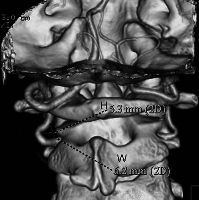
VR-3D image view from back to front showing the measurement method of the second curve (H is the height of the curve, and W is the width)
Fig. 2.
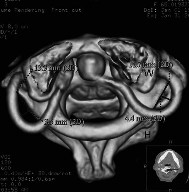
VR-3D image view from up to down, showing the measurement method of the fourth curve (H is the height of the curve, and W is the width)
Fig. 3.
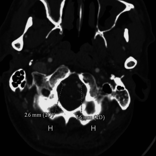
MPR-3D image showing the measurement method of the fifth curve (H is the height of the curve)
Results
Anatomy and variations
The anatomy and variations of CJVA and C0-1-2 were clearly and directly shown in 3D images (Figs. 4, 5, 6). CJVA goes along C0-1-2, extending from the transverse foramen of C2 through foramen magnum to basilar artery. There were 72 cases (81.8%) with five curves in the course of CJVA (Fig. 5, 6). In the total of 88 cases, variations of CJVA exist in 16 cases, of which 8 cases were found abnormal course (5 on the left, 2 on the right and 1 on both, Fig. 7), 3 cases abnormal branch (2 on the left and 1 on both, Fig. 8), 4 cases small in size (1 on the left, 3 on the right) and 1 case absence of VA on the right (Fig. 9). Variations of C1 were found in 12 cases, of which 7 cases were congenital arcuate foramen (Fig. 4), and 5 cases were congenital defects of posterior arch. No variations were found in C0 or C2.
Fig. 4.
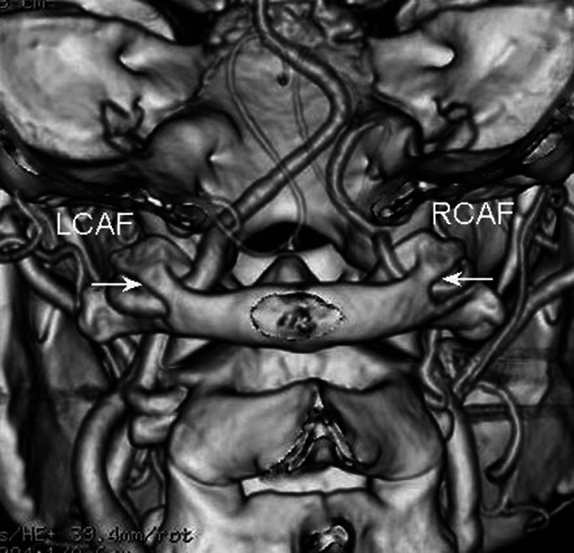
VR-3D image view from back to front, showing the variation of the congenital arcuate foramen of the atlas vertebra (the white arrow and label)
Fig. 5.
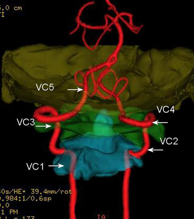
3D image view from back to front with the SFOFC, showing the courses of CJVA with five curves (the white arrow and label) and the fifth curve with an irregular shape whose width is difficult to measure (VC5)
Fig. 6.
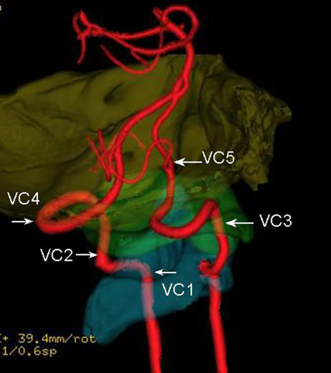
The same subject as in Fig. 5, the left lateral view of 3D image with the SFOFC, showing the courses of CJVA with five curves (the white arrow and label) and the fifth curve with an irregular shape whose width is difficult to measure (VC5)
Fig. 7.
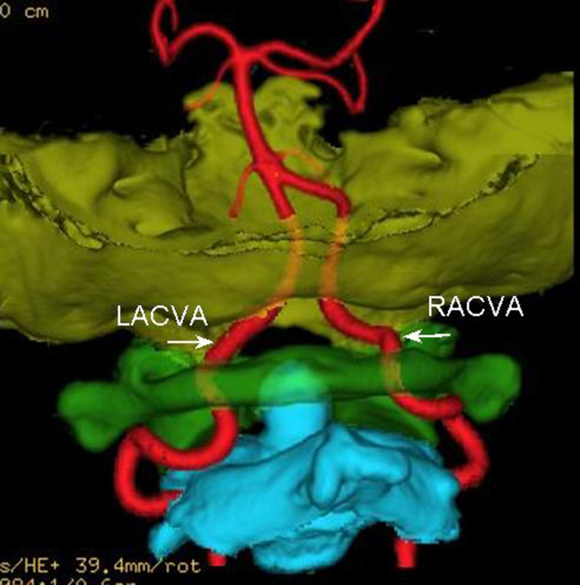
3D image view from back to front with the SFOFC, showing the abnormal courses of CJVA (the white arrow and LACVA and RACVA label)
Fig. 8.
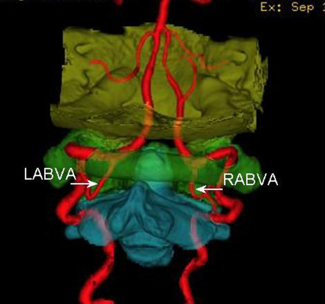
3D image view from back to front with the SFOFC, showing the abnormal branch of CJVA (the white arrow and LABVA and RABVA label)
Fig. 9.
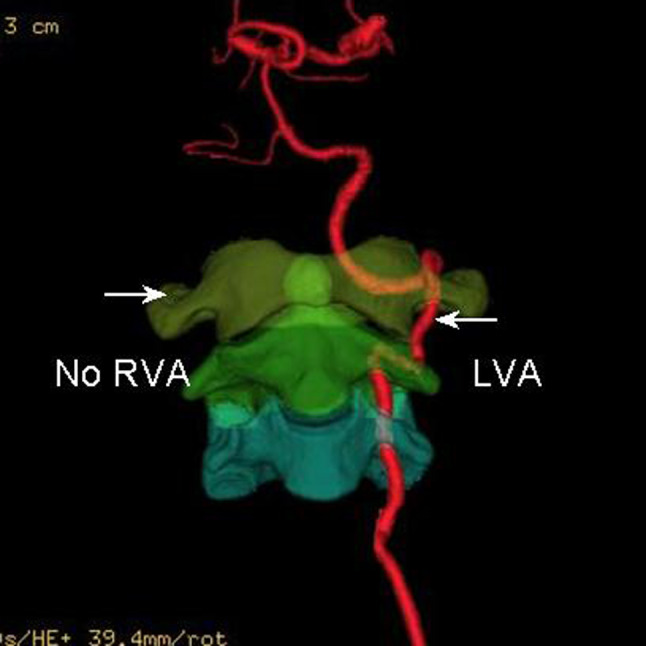
3D image view from front to back with the SFOFC, showing the congenital absence of VA (the white arrow and no RVA label)
Course of CJVA
The curves of CJVA are almost arc-shaped except the fifth, with the first curve going through the transverse foramen of C2, the second going up beside C1-2, the third going through the transverse foramen of C1, the fourth going on or above the posterior arch of C1. The fifth goes forward and through foramen magnum to basilar artery with an irregular shape whose width is difficult to measure (Figs. 5, 6). CJVA is not equal in size. The curved parts slightly expand. The biggest is in the left fourth curve with 5.6 mm in size, and the narrowest is in the right fifth curve with less than 1.0 mm. Statistical comparison shows the left CJVA is larger than the right in the fifth curve (Table 1, P < 0.05).
Table 1.
The mean of the second, fourth and fifth curve of CJVA in size (CCJVA, S) between the left and right (X ± S)
| Measuring parameter | Left (60) | Right (60) | t value | P value |
|---|---|---|---|---|
| Second CCJVA (S, mm) | 3.49 ± 0.48 | 3.24 ± 0.55 | 2.6528 | >0.05 |
| Fourth CCJVA (S, mm) | 3.72 ± 0.46 | 3.51 ± 0.67 | 2.0991 | >0.05 |
| Fifth CCJVA (S, mm) | 2.88 ± 0.55 | 2.41 ± 0.46 | 5.0772 | <0.05 |
Measurement about CJVA and C0-1-2
In the total of 88 cases, except 28 case variations of CJVA and C0-1-2, CJVA of 60 cases with five curves were measured. Statistical comparison shows that the curves become more obvious with the increase of age (smaller open and farther away from C0-1-2, Table 2). Among the five curves, there are three departures visibly away from C0-1-2, one is 0.0–8.3 mm away at the second curve with 0.0–11.2 mm in width, another is 0.0–9.2 mm away at the fourth with 2.8–14.8 mm and the other is 0.0–6.2 mm away at the fifth. There is no significant difference in the measurements between left and right (Table 3, P > 0.05).
Table 2.
The mean of the second, fourth and fifth curves of CJVA (CCJVA) in height (H), size (S) and/or width (W) between the subjects over 60 years and below (X ± S)
| Measuring parameter | ≥60 years (26 × 2a) | <60 years (34 × 2a) | t value | P value | |
|---|---|---|---|---|---|
| Second CCJVA | H (mm) | 2.84 ± 0.49 | 2.59 ± 0.37 | 3.0705 | <0.05 |
| W (mm) | 5.01 ± 0.83 | 5.58 ± 1.06 | 3.3043 | <0.05 | |
| S (mm) | 3.50 ± 0.53 | 3.25 ± 0.61 | 2.3974 | >0.05 | |
| Fourth CCJVA | H (mm) | 4.42 ± 0.96 | 3.83 ± 0.85 | 3.5036 | <0.05 |
| W (mm) | 7.68 ± 1.73 | 8.39 ± 1.43 | 2.3978 | >0.05 | |
| S (mm) | 3.89 ± 0.60 | 3.48 ± 0.49 | 4.0999 | <0.05 | |
| Fifth CCJVA | H (mm) | 3.32 ± 0.85 | 3.01 ± 0.73 | 2.2031 | >0.05 |
| S (mm) | 3.02 ± 0.45 | 2.91 ± 0.83 | 0.9291 | >0.05 | |
a“×2” represents the combined measurements of the left and right
Table 3.
The mean of the second, fourth and fifth curve of CJVA (CCJVA) in height (H) and/or width (W) between the left and right (X ± S)
| Measuring parameter | Left (60) | Right (60) | t value | P value | |
|---|---|---|---|---|---|
| Second CCJVA | H (mm) | 3.21 ± 0.57 | 2.89 ± 0.87 | 1.7126 | >0.05 |
| W (mm) | 5.41 ± 1.06 | 5.05 ± 1.33 | 1.6393 | >0.05 | |
| Fourth CCJVA | H (mm) | 4.12 ± 0.55 | 4.31 ± 0.90 | 1.1889 | >0.05 |
| W (mm) | 7.60 ± 1.75 | 8.04 ± 1.49 | 1.4829 | >0.05 | |
| Fifth CCJVA | H (mm) | 2.92 ± 0.75 | 3.05 ± 0.93 | 0.8431 | >0.05 |
The width of the fifth curve is not measured because of its irregular shape
Discussion
Clinical significance
Because of the complicated course and structure, CJVA and C0-1-2 cannot be clearly and directly shown by the conventional two-dimensional image. 3DCTA, with the advantages of showing clearly the spatial location and bone marks, can be a valuable means of observing the anatomy and variations of CJVA and C0-1-2 [10, 12, 17, 22]. It is helpful in observing the size, shape and course of CJVA and in evaluating the blood supply of vertebro-basilar artery. Imaging anatomy can make up of or enrich the content of regional anatomy, and provide reliable basis for the clinical diagnosis and treatment. Identifying anatomy and variations of CJVA and C0-1-2 is necessary in the choice and plan of surgery and raise the accuracy and safety of operations [6, 10].
Imaging anatomy and the characteristic
The CJVA is accompanied with C0-1-2 with five curves by 81.8%. It is subject to restriction when going through the transverse foramen of C1 or C2. The second, fourth and fifth curves keep off C0-1-2. The distance will be helpful for open surgery, percutaneous injections and biopsies on the region. Statistical comparison between the measurements of size in the left and right fifth curve shows that the left is larger than the right; it proves that the blood supply of VA is asymmetry. The curves become smaller and farther away from C0-1-2 with the increase of age. That is why, for the elder people, the blood of VA flows with more resistance and thus may probably result in vertebro-basilar artery insufficiency and influence normal functions of corresponding organs, such as inner ear, diencephalon, brain stem, cerebellum and so on. These results are not found in any previous reports. Imaging anatomy can show the different surface or deep structure in every direction, and the imaging data can be analyzed and discussed repeatedly [3, 15].
Variations about the CJVA and C0-1-2
In our study, the abnormal course of CJVA and heteroplasia of C1 are found. These variations are multifarious and unexpected, which may cause VA and C0-1-2 malfunctions. The variational structure is easily influenced by outside force, such as neck massage and external injury [18–20]. Identification of these variations can prevent potential injured danger, and provide anatomic basis for diagnosis and treatment of the related discord. Ascertaining the variations before operation can enable us to make a reasonable plan of surgery and avoid injure to VA or related structures.
Advantages of 3DCT in anatomy
Satisfactory 3D image of CJVA and C0-1-2 is the basis for imaging anatomy. With the improvement of CT scanning and imaging technique, the quality of 3D image has been improving continuously and is up to the clinical accurate requirements. Both CJVA and C0-1-2 can be clearly and directly shown in the same image because of their close relations and the similar density. Certainly, for a clearer observation and measurement their anatomy, we can use the techniques of SFOFC on 3D imaging, as it can show VA or CJVA alone as in DSA image and the C0, C1 and C2 alone as bone specimen [7]. By adjusting the tissue’s CT value threshold and different colors or opacity, 3D images can show the different surface or deep anatomic structure at the same image in every direction, and the imaging data obtained can be analyzed and discussed repeatedly [15]. It is an important method to study the 3D anatomy of bone and blood vessel [4, 11].
Application of imaging anatomy
Showing clearly the anatomy and variations of CJVA and C0-1-2 is one of the research hotspots in medical imaging. Other imaging examinations such as ultrasound, MRI, conventional angiography or DSA have some defections or shortcomings; they cannot show both CJVA and C0-1-2 on an image [12–14]. 3DCTA can clearly and directly show not only the anatomy and variations of VA but also its wall calcification and other pathological changes. Moreover, it can differentiate the narrow or blocking of VA and judge the causes, which can be the basis for treatment plans. Abnormal or various C0-1-2 such as atlantoaxial subluxation or congenital arcuate foramen of the C1 may result in distortion, narrow of CJVA. Showing the relations between CJVA and C0-1-2 is a basis for diagnosing abnormality of atlantoaxial joint and CJVA, and can provide the anatomy foundation for the choice of operation [3, 10, 16].
Summary
The anatomy of CJVA and C0-1-2 is complicated with some unexpected variations. With five curves, CJVA is not equal in size, and statistical comparison shows the left CJVA is larger than the right in the fifth curve. These curves become more obvious with the increase of age. These results give important anatomic basis for the study on the hemodynamics of VA and operation at the craniocervical junction.
Acknowledgments
We would like to thank the sustentation from the Fund of Xiamen City’s Scientific and Technical Program (3502Z 20064008) and National Natural Science Foundation (30870690), China.
References
- 1.Bruneau M, Cornelius JF, George B. Antero-lateral approach to the V3 segment of the vertebral artery. Neurosurgery. 2006;58:29–35. doi: 10.1227/01.neu.0000193930.74183.42. [DOI] [PubMed] [Google Scholar]
- 2.Cacciola F, Phalke U, Goel A. Vertebral artery in relationship to C1–C2 vertebrae: an anatomical study. Neurol India. 2004;52:178–184. [PubMed] [Google Scholar]
- 3.Duan SY, Huang XE, Lin QC, Chen GN. Clinical significance of articulating facet displacement of lateral atlantoaxial joint on 3D CT in diagnosing atlantoaxial subluxation. J Formos Med Assoc. 2007;106:840–846. doi: 10.1016/S0929-6646(08)60049-2. [DOI] [PubMed] [Google Scholar]
- 4.Duan SY, Ye F, Kang JH. Three-dimensional CT study on normal anatomical features of atlanto-axial joints. Surg Radiol Anat. 2007;29:83–88. doi: 10.1007/s00276-006-0166-0. [DOI] [PubMed] [Google Scholar]
- 5.Hong JT, Lee SW, Son BC, Sung JH, Yang SH, Kim IS, Park CK. Analysis of anatomical variations of bone and vascular structures around the posterior atlantal arch using three-dimensional computed tomography angiography. J Neurosurg Spine. 2008;8:230–236. doi: 10.3171/SPI/2008/8/3/230. [DOI] [PubMed] [Google Scholar]
- 6.Huynh-Le P, Matsushima T, Miyazono M, Sayama T, Muratani H, Tashima T, Sasaki T. Three-dimensional CT angiography for the surgical management of the vertebral artery-posterior inferior cerebellar artery aneurysms. Acta Neurochir (Wien) 2004;146:329–335. doi: 10.1007/s00701-003-0157-4. [DOI] [PubMed] [Google Scholar]
- 7.Lell MM, Ditt H, Panknin C, Sayre JW, Klotz E, Ruehm SG, Villablanca JP. Cervical CT angiography comparing routine noncontrast and a late venous scan as masks for automated bone subtraction: feasibility study and examination of the influence of patient motion on image quality. Invest Radiol. 2008;43:27–32. doi: 10.1097/RLI.0b013e31815597ac. [DOI] [PubMed] [Google Scholar]
- 8.Malhotra AK, Camacho M, Ivatury RR, Davis IC, Komorowski DJ, Leung DA, Grizzard JD, Aboutanos MB, Duane TM, Cockrell C, Wolfe LG, Borchers CT, Martin NR. Computed tomographic angiography for the diagnosis of blunt carotid/vertebral artery injury: a note of caution. Ann Surg. 2007;246:632–643. doi: 10.1097/SLA.0b013e3181568cab. [DOI] [PubMed] [Google Scholar]
- 9.Moftakhar P, Gonzalez NR, Khoo LT, Holly LT. Osseous and vascular anatomical variations within the C1–C2 complex: a radiographical study using computed tomography angiography. Int J Med Robot. 2008;4:158–164. doi: 10.1002/rcs.193. [DOI] [PubMed] [Google Scholar]
- 10.Neo M, Matsushita M, Iwashita Y, Yasuda T, Sakamoto T, Nakamura T. Atlantoaxial transarticular screw fixation for a high-riding vertebral artery. Spine. 2003;28:666–670. doi: 10.1097/00007632-200304010-00009. [DOI] [PubMed] [Google Scholar]
- 11.Petridis AK, Barth H, Buhl R, Mehdorn HM. Vertebral artery decompression in a patient with rotational occlusion. Acta Neurochir (Wien) 2008;150:391–394. doi: 10.1007/s00701-008-1502-4. [DOI] [PubMed] [Google Scholar]
- 12.Pugliese F, Crusco F, Cardaioli G, Tambasco N, Boranga B, Scaroni R, Maselli A, Lupattelli L. CT angiography versus colour-Doppler US in acute dissection of the vertebral artery. Radiol Med (Torino) 2007;112:435–443. doi: 10.1007/s11547-007-0152-6. [DOI] [PubMed] [Google Scholar]
- 13.Puchner S, Haumer M, Rand T, Reiter M, Minar E, Lammer J, Bucek RA. CTA in the detection and quantification of vertebral artery pathologies: a correlation with color Doppler sonography. Neuroradiology. 2007;49:645–650. doi: 10.1007/s00234-007-0234-0. [DOI] [PubMed] [Google Scholar]
- 14.Ren X, Wang W, Zhang X, Pu Y, Jiang T, Li C. Clinical study and comparison of magnetic resonance angiography (MRA) and angiography diagnosis of blunt vertebral artery injury. J Trauma. 2007;63:1249–1253. doi: 10.1097/TA.0b013e31815bd78d. [DOI] [PubMed] [Google Scholar]
- 15.Sparacia G, Bencivinni F, Banco A, Sarno C, Bartolotta TV, Lagalla R. Imaging processing for CT angiography of the cervicocranial arteries: evaluation of reformatting technique. Radiol Med (Torino) 2007;112:224–238. doi: 10.1007/s11547-007-0137-5. [DOI] [PubMed] [Google Scholar]
- 16.Sawlani V, Behari S, Salunke P, Jain VK, Phadke RV. “Stretched loop sign” of the vertebral artery: a predictor of vertebrobasilar insufficiency in atlantoaxial dislocation. Surg Neurol. 2006;66:298–304. doi: 10.1016/j.surneu.2006.02.032. [DOI] [PubMed] [Google Scholar]
- 17.Sylaja PN, Puetz V, Dzialowski I, Krol A, Hill MD, Demchuk AM. Prognostic value of CT angiography in patients with suspected vertebrobasilar ischemia. J Neuroimaging. 2008;18:46–49. doi: 10.1111/j.1552-6569.2007.00174.x. [DOI] [PubMed] [Google Scholar]
- 18.Senoglu M, Safavi-Abbasi S, Theodore N, Bambakidis NC, Crawford NR, Sonntag VK. The frequency and clinical significance of congenital defects of the posterior and anterior arch of the atlas. J Neurosurg Spine. 2007;7:399–402. doi: 10.3171/SPI-07/10/399. [DOI] [PubMed] [Google Scholar]
- 19.Sanelli PC, Tong S, Gonzalez RG, Eskey CJ. Normal variation of vertebral artery on CT angiography and its implications for diagnosis of acquired pathology. J Comput Assist Tomogr. 2002;26:462–670. doi: 10.1097/00004728-200205000-00027. [DOI] [PubMed] [Google Scholar]
- 20.Tubbs RS, Johnson PC, Shoja MM, Loukas M, Oakes WJ. Foramen arcuale: anatomical study and review of the literature. J Neurosurg Spine. 2007;6:31–34. doi: 10.3171/spi.2007.6.1.6. [DOI] [PubMed] [Google Scholar]
- 21.Utter GH, Hollingworth W, Hallam DK, Jarvik JG, Jurkovich GJ. Sixteen-slice CT angiography in patients with suspected blunt carotid and vertebral artery injuries. J Am Coll Surg. 2006;203:838–848. doi: 10.1016/j.jamcollsurg.2006.08.003. [DOI] [PubMed] [Google Scholar]
- 22.Yamazaki M, Koda M, Aramomi MA, Hashimoto M, Masaki Y, Okawa A. Anomalous vertebral artery at the extraosseous and intraosseous regions of the craniovertebral junction: analysis by three-dimensional computed tomography angiography. Spine. 2005;30:2452–2457. doi: 10.1097/01.brs.0000184306.19870.a8. [DOI] [PubMed] [Google Scholar]


