Abstract
Successful placement of cervical pedicle screws requires accurate identification of both entry point and trajectory. However, literature has not provided consistent recommendations regarding the direction of pedicle screw insertion and entry point location. The objective of this study was to define a guideline regarding the optimal entry point and trajectory in placing subaxial cervical pedicle screws and to evaluate the screw accuracy in cadaver cervical spines. The guideline for entry point and trajectory for each vertebra was established based on the recently published morphometric data. Six fresh frozen cervical spines (C3–C7) were used. There were two men and four women. After posterior exposure, the entry point was determined and the cortical bone of the entry point was removed using a 2-mm burr. Pilot holes were created with a cervical probe based on the guideline using fluoroscopy. After tapping, 3.5-mm screws with appropriate length were inserted. After screw insertion, every vertebra was dissected and inspected for pedicle breach. The pedicle width, height, pedicle transverse angulation and actual screw insertion angle were measured. A total of 60 pedicle screws were inserted. No statistical difference in pedicle width and height was found between the left and right sides for each level. The overall accuracy of pedicle screws was 83.3%. The remaining 13.3% screws had noncritical breach, and 3.3% had critical breach. The critical breach was not caused by the guideline. There was no statistical difference between the pedicle transverse angulation and the actual screw trajectory created using the guideline. There was statistical difference in pedicle width between the breach and non-breach screws. In conclusion, high success rate of subaxial cervical pedicle screw placement can be achieved using the recently proposed operative guideline and oblique views of fluoroscopy. However, careful preoperative planning and good surgical skills are still required to ensure screw placement accuracy and to reduce the risk of neural and vascular injury.
Keywords: Cervical spine, Pedicle screw, Entry point, Trajectory
Introduction
Because of the improved biomechanical stability, cervical pedicle screws not only allow for shorter instrumentation with sagittal correction [11, 12, 15, 22, 26], but also are valuable for simultaneous posterior decompression and reconstruction [1–3]. The accuracy of screw placement in subaxial cervical spines varied significantly in literature, ranging from 16.8 to 97% [14, 17, 18, 21, 23]. Proper placement of a pedicle screw in the cervical spine requires thorough understanding of the three-dimensional vertebral morphology to accurately identify the best screw entry point and trajectory. Because of the small size of the cervical pedicles, minor deviations from the entry point and trajectory may lead to pedicle breach, possibly resulting in neural or vascular injury [4, 9]. Because of the catastrophic consequence of neural or vascular injuries, various surgical techniques have been developed, including the use of laminoforamenotomy to palpate the medial and superior pedicle walls [6, 8, 17, 18], the “funnel technique” [14], cannulated screws [23] and the computer-assisted navigation system [17, 24]. The navigation system has been shown to improve screw accuracy significantly, but has limited application due to its high cost and lengthy registration procedure. Furthermore, surgical skills and experience are still needed and the surgeon should never solely rely on the navigation system [23, 24].
Without the navigation system, placement of pedicle screws in subaxial cervical spines requires precise definition of entry point and screw trajectory preoperatively. However, literature has not provided consistent recommendations for these two parameters [1, 2, 10, 13, 16, 17]. These recommended values varied significantly and made screw insertion very challenging in surgical practice. Although high screw accuracy (91%) has been achieved with specialized surgical tools and cannulated screws, the consistent entry point and trajectory values for each pedicle were not given and must be measured preoperatively from CT scans of each vertebra for every patient [23]. Recently, an anatomical study of subaxial cervical pedicles and lateral masses using CT scans measured 98 asymptomatic adult volunteers and provided a method to determine the entry point and trajectory for subaxial cervical pedicle screws [20, 27]. Compared with other studies, the screw entry point and trajectory recommended in this study were more consistent and repeatable. However, no independent study has been performed to validate this approach on human cadavers or patients. Thus, the purpose of this study was to evaluate the accuracy of cervical pedicle screws inserted according to the recently published recommendations on screw entry point and trajectory.
Materials and methods
Definition of the entry point and trajectory of subaxial cervical pedicle screws
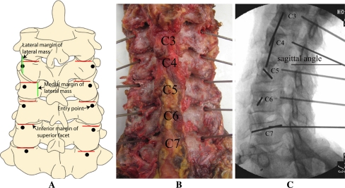
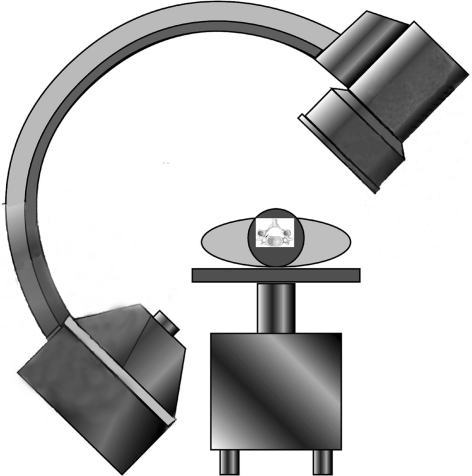
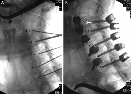
The guideline for screw entry point and trajectory for each individual level is shown in Table 1 and Fig. 1. The original recommendation given by Rao et al. was modified for easier surgical application. The sagittal angles given by Rao et al. [20] were not used as they were highly affected by cervical alignment, caused by disc degeneration in patients, and intraoperative neck position. Instead, the sagittal angles were determined intraoperatively using oblique fluoroscopy. The C-arm was placed perpendicularly to the longitudinal axis of the cervical spine and centered on the C5 vertebra. The angle of the C-arm was adjusted to see the maximal length of the pedicle as shown in Fig. 2. After the entry point and transverse angle were determined in the axial plane, the sagittal angle (in the sagittal plane) was guided by oblique fluoroscopy to direct the pedicle probe to the center of each pedicle (Fig. 1c).
Table 1.
The entry point and trajectory used in this study according to quantitative data measured by Rao et al. [20, 27]
| Level | Entry point | Trajectory (degrees) | ||
|---|---|---|---|---|
| Axial plane | Sagittal plane | Transverse angle | Sagittal angle | |
| C3 | The lateral margin of the lateral mass | 4 mm from the inferior margin of the superior articular facet | 45–50 | According to C-arm oblique fluoroscopy |
| C4 | One-fourth medial to the width of the lateral mass | 3 mm from the inferior margin of the superior articular facet | 45–50 | |
| C5 | One-fourth medial to the width of the lateral mass | 3 mm from the inferior margin of the superior articular facet | 45 | |
| C6 | One-fourth medial to the width of the lateral mass | 2 mm from the inferior margin of the superior articular facet | 40–45 | |
| C7 | One-half of the width of the lateral mass | 2 mm from the inferior margin of the superior articular facet | 30–35 | |
Fig. 1.
Entry point and trajectory for C3–C7 pedicle screws
Fig. 2.
The position of C-arm related to the cadaver
Surgical techniques
Six fresh frozen cadaver specimens (C3–C7) were used (60 pedicles). There were two men and four women. The average donor age was 68 years. The average height was 171 ± 6.7 cm. None of these donors had evidence of infectious or neoplastic diseases, nor congenital or developmental spinal malformations. All specimens had various degrees of degenerative changes.
The cadavers were placed prone, with the neck in the neutral position. A midline incision was made from the external occipital protuberance to the spinous process of T2. All soft tissues of the posterior aspect of the cervical spine were dissected and retracted laterally. The lateral margins of the lateral masses were exposed.
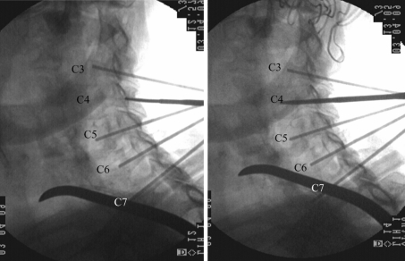
The entry point was located according to Table 1. Any existing osteophytes of the inferior facet process were removed before the cortical bone of the entry point could be removed with a 2-mm burr. A small cervical probe was used to advance into each pedicle to create the pilot hole. The transverse angle was determined from Table 1 and verified with an angle finder. The sagittal angle and insertion depth were guided by oblique view fluoroscopy (Fig. 3). The probe had a flat tip and was rotated back and forth by a quarter turn in each direction to expand the pilot hole for easier screw insertion. This procedure was carefully and slowly performed to avoid accidental injury of neural and vascular structures. The feel of the surgeon’s hands was very important during this process. When hard and cortical bone was felt near the tip, it was difficult to advance the probe. In this case, the transverse angulation of the probe was slightly adjusted (<5° in each direction). However, it must be noted that some pedicles had no cancellous bone at the center. In this case, a 2-mm hand drill was used to create the pilot hole instead of a blunt-tipped pedicle probe. Once the pilot hole was created, the pilot hole trajectory was verified and the pedicle wall was checked using a pedicle feeler. Tapping was performed and the pedicle wall was checked again. A 3.5-mm pedicle screw was gently inserted (Sofmor Danek, Memphis, TN) into the tapped hole. The screw length was selected according to the pedicle length of each level. After the screws were placed, the anterior–posterior, lateral and left and right oblique views were recorded by fluoroscopy.
Fig. 3.
C4 pilot hole was prepared with a 2-mm probe
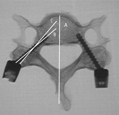
Each vertebra was then dissected from the cadavers. All the soft tissues around the pedicles were removed to inspect each pedicle. X-ray images were obtained in the axial plane for each vertebra. The pedicle transverse angulation (the optimal screw trajectory) and the actual screw trajectory in axial plane were measured with ImageJ (Fig. 4). Two spine surgeons inspected each vertebra and verified the screw position. The screw position was classified in the following manner: grade 1, pedicle screw remained inside the pedicle and the pedicle wall was intact; grade 2, minor bone breach on the pedicle wall, but screw still remained inside the pedicle; grade 3, the pedicle wall was perforated, but <1 mm of the screw was out; grade 4, the pedicle wall was perforated and more than 1 mm was out. The width (the medial–lateral outer cortical width of the pedicle) and height (the superior–inferior outer cortical width of the pedicle) of each pedicle were measured with an electronic caliper (Mitutoyo Corp., Japan) at a precision of 0.01 mm after the screws had been removed.
Fig. 4.
Measurement of pedicle transverse angulation and actual screw trajectory. Pedicle transverse angulation: the angle between line A and C. Actual screw trajectory: the angle between line A and B
Statistical analysis
Measured data were analyzed using SPSS 13.0. The accuracy of screw position (grade I and grade II were considered to be accurate) between the left and right side was compared by Fischer’s exact test.
The pedicle width and height, and pedicle transverse angulation were compared between the left and right side using paired t test. Paired t test was also used to compare the pedicle transverse angulation with the actual screw trajectory. The pedicle width between non-breached and breached screws was compared using the t test. Difference with P values <0.05 was considered to be statistically significant.
Results
Sixty pedicles were inserted in this study. The average pedicle width of each level was: C3, 5.1 ± 1.1 mm; C4, 5.7 ± 0.9 mm; C5, 5.9 ± 1.2 mm; C6, 6.3 ± 1.1 mm; and C7, 7.1 ± 1.0 mm. The average height was: C3, 6.2 ± 1.2 mm; C4, 6.4 ± 1.0 mm; C5, 6.3 ± 0.9 mm; C6, 6.5 ± 1.0 mm; and C7, 6.5 ± 1.3 mm. No statistically significant difference in pedicle width and height was found between left and right sides for each level (P = 0.468 and 0.697).
The average pedicle transverse angulation for each vertebral level was: C3, 50° ± 2°; C4, 49° ± 3°; C5, 46° ± 5°; C6, 43° ± 3°; and C7, 34° ± 4°. The actual screw insertion angles were: C3, 48° ± 3°; C4, 47° ± 2°; C5, 44° ± 6°; C6, 43° ± 3°; and C7, 33° ± 4°. For each level, there was no statistical difference between the left and right side (P = 0.376). No statistical difference was found between the pedicle transverse angulation and actual screw trajectory (P = 0.290).
There was no statistical difference for accuracy rate of screw insertion between the left and right side (P = 0.846). The overall grade 1 accuracy of pedicle screws was 83.3% (50/60). The percentage according to levels was: C3, 66.7% (8/12); C4; 66.7% (8/12); C5, 83.3% (10/12); C6, 100% (12/12); and C7, 100% (12/12).
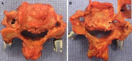
The overall percentage of noncritical breach was 13.3% (8/60, 5 for grade 2 and 3 for grade 3, Fig. 5). The percentage according to level was: C3, 25% (3/12); C4; 33.3% (4/12); C5, 8.3% (1/12); C6, 0% (0/12), and C7, 0% (0/12). All eight screws breached the lateral or superior lateral walls of the pedicles. For the eight breached pedicles, minor breach was detected in three tapped pilot holes.
Fig. 5.
a Grade 2 (6 screws). Pedicle wall was breached (arrowhead), but the screw remained inside the pedicle. b Grade 3 (2 screws). Pedicle wall was fractured (arrowhead), but <1 mm of the screw was out
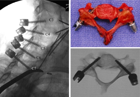
The overall percentage of grade 4 critical breach was 3.3% (2/60): one was in the right pedicle of the C3 and another in the left pedicle of C5. For the C3 screw, the entry point and trajectory were correctly created by the probe (Fig. 6a). Intact cortical wall was also confirmed after tapping. The screw was in the wrong direction and perforated the inferior wall of the pedicle, which might have damaged the nerve root (Fig. 6b). The C5 screw was inserted into the vertebral hole along the lateral wall of the pedicle (Fig. 7). Detailed examination of the specimen suggested that the entry point was 2 mm more lateral than the recommended guideline. After the screw was removed, another pilot hole was found in the pedicle and the pilot hole trajectory was 53° in transverse angle.
Fig. 6.
The trajectory of the C3 screw was correct, but the screw breached the inferior side of the pedicle wall (arrowhead). The distance of the C3 and C4 screw heads was so close that there was no room for the head of the C3 screw to get the correct direction (the C4 screw was inserted first)
Fig. 7.
The left C5 screw appears to have good position in oblique view, but it was completely out from the axial view. The entry point was approximately 2 mm more lateral than the recommended location
The average pedicle width was 5.83 ± 1.71 mm for the correctly placed pedicle screws (grade 1, 50 screws); 5.12 ± 1.23 mm for the pedicle with perforation (10 screws, grade 2, 3 and 4). The difference was statistically significant (P = 0.037).
Discussion
Until recently, the recommendation for entry point location and trajectory of cervical pedicle screws has been inconsistent in literature. Jeanneret et al. [10] recommended that the entry point should be located at the middle of the lateral mass and 3 mm below the superior facet. A transverse angle of 45° was proposed for all subaxial levels (C3–C7). Abumi et al. [1, 2, 5] suggested that the entry point should be slightly lateral to the center of the lateral mass and close to the inferior margin of the cranially adjacent vertebra. The desirable transverse angle should be 25°–40° medial to the midline in the transverse plane, and parallel to the upper end plate in the sagittal plane. Several morphological studies have proposed different entry points and transverse angles. Karaikovic et al. [13] measured 53 human cadaver cervical spines (C2–C7) and suggested different entry point locations for different cervical levels. The pedicle entrance was located at the lateral vertebral notch at C3 and C4, and gradually moved medially away from the notch at C5–C7. The transverse angle was not established based on these entry point locations. Sakamoto et al. [25] measured the space available for screws at 25° or 50° transverse angles on axial CT scans and recommended that the transverse angle should be 50° at C3–C6 and 35° at C7. Similar results were also found by Hacker et al. [7] using the contralateral lamina angle as the desired transverse angle. This wide variation in entry point and transverse angle recommendation has led to various screw accuracies [4, 9, 17, 21].
The funnel technique seems to have high screw accuracy without the navigation system and precisely defined entry point and trajectory [14]. But this technique requires removal of large bone stock of the lateral mass. Screw fixation strength may be significantly reduced. In some cases, the funnel may not exist (absence of medullary canal) to locate the pedicle. Furthermore, this technique also loses the chance for a lateral mass screw when the pedicle screw has failed or cannot be inserted. Ricther et al. [23] reported the highest screw accuracy (91% without navigation system and 97% with navigation system) with cannulated screws and specialized surgical tools. However, the entry point and trajectory values in their study must be measured preoperatively from CT scans of each vertebra for every patient. Such measurement is often arbitrary and its application to surgical practice is yet to be verified on surgeons with different experience and skill levels. Therefore, a more consistent surgical guideline is still required to achieve better and more predictable results. This study proposed a more consistent guideline for entry point and trajectory based on the anatomical data of Rao et al. [20]. The results of this study showed that 83.3% of the screws were totally within the pedicles and 13.3% had <1-mm pedicle wall breach. Only 3.3% screws had critical breach. Overall, 97% of the screws had no injuries to vertebral arteries, spinal cord and nerve root. The guideline defined in this study worked well for all the specimens.
The screws that have critical breach were not caused by the guideline itself. In one screw placed on C3, the entry point and trajectory were correct. Intact cortical wall was confirmed with the pedicle feeler after tapping. However, the screw did not follow the tapped pilot hole and breached the inferior side of the pedicle wall. Detailed examination of the specimen suggested that the distance between the C3 and C4 screws was very close, as shown in Fig. 6. The screw heads of C3 and C4 screws interfered with each other so that the C3 screw was forced to deviate from its correct trajectory (C4 screw was inserted first). Hence, the failure of this screw could have been avoided if a smaller screw head was used. Another option was to apply a lateral mass screw at C4 or C3. According to the recommendation proposed by Rao et al., the entry points between C3 and C4 had the smallest distance. It is highly possible that C3 and C4 screws interfere with each other in patients with small cervical spine, unless the screw head size is reduced. Surgeons must be aware of this situation and should not force screws into C3 or C4 when screw interference does occur. The critical breach of the other screw (placed on C5) was caused by a different reason. The entry point was created at 2 mm more lateral than the recommended location. The author was able to create a good pilot hole using his hand feeling. However, the trajectory of the pilot hole had a transverse angle of 53°. This trajectory was appropriate for the misplaced entry point, but was much larger than the recommended value of 45°. The author still tapped the pilot hole at about 45° that resulted in serious breach into the transverse foramen. After tapping, there were two trajectories: the original pilot hole and the newly tapped hole. The surgeon checked the pilot hole and assumed that the original pilot hole was tapped because no breach was detected. A screw was inserted, but ended up in the wrong tapped hole. The lesson we learned from this mistake was that we should determine the entry point carefully because the small deviation of the entry point might cause disastrous results. While the guideline provided accurate and effective estimate of entry point and trajectory, it should be applied with caution. If the entry point moved from its desired location, the transverse angle must also be adjusted. Feeling with hand is still very important considering the anatomic variation of patients. Another lesson we have learned is that we should not assume and always double check the trajectory carefully. In summary, these two cases of critical breach were caused by different reasons but could have been avoided with increased experience. The guideline remained useful in these two cases.
The results of this study showed accurate placement of pedicle screws at all C6 and C7. The authors believed that the placement of pedicle screws in C6 and C7 was relatively safer according to the entry point and trajectory defined in Table 1. For the eight screws with minor breach of pedicle wall, there were three screws in C3, four on C4 and one in C5. Between the screws with and without pedicle breach, the pedicle width had statistical difference. Previous studies also found increased risk of critical perforation in pedicles with an isthmic outer diameter of <4.5 mm [16]. It is common sense that small pedicles will have more perforations. Because of the small size of the medullary canal and thinner lateral cortex of the pedicle [19], it is easier to breach the lateral wall during tapping, even the pilot hole was correct. In this study, all eight noncritical breaches occurred laterally or superior laterally, and no medial breach occurred. This result was similar to the previous reports in which most injuries were inflicted on the vertebral artery [17].
In conclusion, a high success rate of subaxial cervical pedicle screw placement can be achieved using the recently proposed operative guideline and oblique views of fluoroscopy. However, careful preoperative planning and good surgical skills are still required to ensure screw placement accuracy and to avoid neural and vascular injury.
References
- 1.Abumi K, Itoh H, Taneichi H, et al. Transpedicular screw fixation for traumatic lesions of the middle and lower cervical spine: description of the techniques and preliminary report. J Spinal Disord. 1994;7:19–28. doi: 10.1097/00002517-199407010-00003. [DOI] [PubMed] [Google Scholar]
- 2.Abumi K, Kaneda K. Pedicle screw fixation for nontraumatic lesions of the cervical spine. Spine. 1997;22:1853–1863. doi: 10.1097/00007632-199708150-00010. [DOI] [PubMed] [Google Scholar]
- 3.Abumi K, Kaneda K, Shono Y, et al. One-stage posterior decompression and reconstruction of the cervical spine by using pedicle screw fixation systems. J Neurosurg. 1999;90:19–26. doi: 10.3171/spi.1999.90.1.0019. [DOI] [PubMed] [Google Scholar]
- 4.Abumi K, Shono Y, Ito M, et al. Complications of pedicle screw fixation in reconstructive surgery of the cervical spine. Spine. 2000;25:962–969. doi: 10.1097/00007632-200004150-00011. [DOI] [PubMed] [Google Scholar]
- 5.Abumi K, Takada T, Shono Y, et al. Posterior occipitocervical reconstruction using cervical pedicle screws and plate–rod systems. Spine. 1999;24:1425–1434. doi: 10.1097/00007632-199907150-00007. [DOI] [PubMed] [Google Scholar]
- 6.Albert TJ, Klein GR, Joffe D, et al. Use of cervicothoracic junction pedicle screws for reconstruction of complex cervical spine pathology. Spine. 1998;23:1596–1599. doi: 10.1097/00007632-199807150-00017. [DOI] [PubMed] [Google Scholar]
- 7.Hacker AG, Molloy S, Bernard J. The contralateral lamina: a reliable guide in subaxial, cervical pedicle screw placement. Eur Spine J. 2008;17:1457–1461. doi: 10.1007/s00586-008-0756-0. [DOI] [PMC free article] [PubMed] [Google Scholar]
- 8.Hardy RW., Jr The posterior surgical approach to the cervical spine. Neuroimaging Clin N Am. 1995;5:481–490. [PubMed] [Google Scholar]
- 9.Hasegawa K, Hirano T, Shimoda H, et al. Indications for cervical pedicle screw instrumentation in nontraumatic lesions. Spine. 2008;33:2284–2289. doi: 10.1097/BRS.0b013e31818043ce. [DOI] [PubMed] [Google Scholar]
- 10.Jeanneret B, Gebhard JS, Magerl F. Transpedicular screw fixation of articular mass fracture-separation: results of an anatomical study and operative technique. J Spinal Disord. 1994;7:222–229. doi: 10.1097/00002517-199407030-00004. [DOI] [PubMed] [Google Scholar]
- 11.Johnston TL, Karaikovic EE, Lautenschlager EP, et al. Cervical pedicle screws vs. lateral mass screws: uniplanar fatigue analysis and residual pullout strengths. Spine J. 2006;6:667–672. doi: 10.1016/j.spinee.2006.03.019. [DOI] [PubMed] [Google Scholar]
- 12.Jones EL, Heller JG, Silcox DH, et al. Cervical pedicle screws versus lateral mass screws. Anatomic feasibility and biomechanical comparison. Spine. 1997;22:977–982. doi: 10.1097/00007632-199705010-00009. [DOI] [PubMed] [Google Scholar]
- 13.Karaikovic EE, Kunakornsawat S, Daubs MD, et al. Surgical anatomy of the cervical pedicles: landmarks for posterior cervical pedicle entrance localization. J Spinal Disord. 2000;13:63–72. doi: 10.1097/00002517-200002000-00013. [DOI] [PubMed] [Google Scholar]
- 14.Karaikovic EE, Yingsakmongkol W, Gaines RW., Jr Accuracy of cervical pedicle screw placement using the funnel technique. Spine. 2001;26:2456–2462. doi: 10.1097/00007632-200111150-00012. [DOI] [PubMed] [Google Scholar]
- 15.Kothe R, Ruther W, Schneider E, et al. Biomechanical analysis of transpedicular screw fixation in the subaxial cervical spine. Spine. 2004;29:1869–1875. doi: 10.1097/01.brs.0000137287.67388.0b. [DOI] [PubMed] [Google Scholar]
- 16.Ludwig SC, Kowalski JM, Edwards CC, 2nd, et al. Cervical pedicle screws: comparative accuracy of two insertion techniques. Spine. 2000;25:2675–2681. doi: 10.1097/00007632-200010150-00022. [DOI] [PubMed] [Google Scholar]
- 17.Ludwig SC, Kramer DL, Balderston RA, et al. Placement of pedicle screws in the human cadaveric cervical spine: comparative accuracy of three techniques. Spine. 2000;25:1655–1667. doi: 10.1097/00007632-200007010-00009. [DOI] [PubMed] [Google Scholar]
- 18.Miller RM, Ebraheim NA, Xu R, et al. Anatomic consideration of transpedicular screw placement in the cervical spine. An analysis of two approaches. Spine. 1996;21:2317–2322. doi: 10.1097/00007632-199610150-00003. [DOI] [PubMed] [Google Scholar]
- 19.Panjabi MM, Duranceau J, Goel V, et al. Cervical human vertebrae. Quantitative three-dimensional anatomy of the middle and lower regions. Spine. 1991;16:861–869. doi: 10.1097/00007632-199108000-00001. [DOI] [PubMed] [Google Scholar]
- 20.Rao RD, Marawar SV, Stemper BD, et al. Computerized tomographic morphometric analysis of subaxial cervical spine pedicles in young asymptomatic volunteers. J Bone Joint Surg Am. 2008;90:1914–1921. doi: 10.2106/JBJS.G.01166. [DOI] [PubMed] [Google Scholar]
- 21.Reinhold M, Magerl F, Rieger M, et al. Cervical pedicle screw placement: feasibility and accuracy of two new insertion techniques based on morphometric data. Eur Spine J. 2007;16:47–56. doi: 10.1007/s00586-006-0104-1. [DOI] [PMC free article] [PubMed] [Google Scholar]
- 22.Richter M, Amiot LP, Neller S, et al. Computer-assisted surgery in posterior instrumentation of the cervical spine: an in vitro feasibility study. Eur Spine J. 2000;9(Suppl 1):S65–S70. doi: 10.1007/PL00010024. [DOI] [PMC free article] [PubMed] [Google Scholar]
- 23.Richter M, Cakir B, Schmidt R. Cervical pedicle screws: conventional versus computer-assisted placement of cannulated screws. Spine. 2005;30:2280–2287. doi: 10.1097/01.brs.0000182275.31425.cd. [DOI] [PubMed] [Google Scholar]
- 24.Richter M, Mattes T, Cakir B. Computer-assisted posterior instrumentation of the cervical and cervico-thoracic spine. Eur Spine J. 2004;13:50–59. doi: 10.1007/s00586-003-0604-1. [DOI] [PMC free article] [PubMed] [Google Scholar]
- 25.Sakamoto T, Neo M, Nakamura T. Transpedicular screw placement evaluated by axial computed tomography of the cervical pedicle. Spine. 2004;29:2510–2514. doi: 10.1097/01.brs.0000144404.68486.85. [DOI] [PubMed] [Google Scholar]
- 26.Schmidt R, Wilke HJ, Claes L, et al. Pedicle screws enhance primary stability in multilevel cervical corpectomies: biomechanical in vitro comparison of different implants including constrained and nonconstrained posterior instumentations. Spine. 2003;28:1821–1828. doi: 10.1097/01.BRS.0000083287.23521.48. [DOI] [PubMed] [Google Scholar]
- 27.Stemper BD, Marawar SV, Yoganandan N, et al. Quantitative anatomy of subaxial cervical lateral mass: an analysis of safe screw lengths for Roy–Camille and Magerl techniques. Spine. 2008;33:893–897. doi: 10.1097/BRS.0b013e31816b4666. [DOI] [PubMed] [Google Scholar]


