Abstract
Background:
Nitric oxide (NO) is a very reactive agent with potentially toxic oxidation products such as nitrogen dioxide (NO2). Therefore, during NO inhalation a constant inspired concentration and accurate measurement of NO and NO2 concentrations are essential. The objective of this study was to test the NO concentrations at various positions along the inspiratory limb of the breathing circuit using a recently developed system to administer NO in phase with inspiratory flow during mechanical ventilation (Servo 300 NO-A, Siemens, Sweden). Furthermore, we tested whether an active heating system would interfere with inspired NO concentrations.
Results:
A sharp decline in the NO concentration was found between the respirator's inspiratory outlet and more distal points along the inspiratory limb of the circuit. This finding was most evident when an active heating system was mounted between those points.
Conclusions:
The concentrations of NO and NO2 should be measured as near to the patient as possible, as significant fluctuations of these concentrations might be found along the inspiratory limb of the respiratory circuit especially when an active heating system is used.
Keywords: acute lung injury, mechanical ventilation, nitric oxide
Introduction
Inhalation of nitric oxide (NO) has been shown to selectively dilate the pulmonary vascular bed in animals as well as in humans [1,2,3,4]. Therefore, it has been used to reduce pulmonary hypertension in neonates [5,6] or after cardiac surgery [7,8]. In contrast to intravenously administered vasodilators, inhaled NO does not exert any vasodilating effect on the systemic circulation due to its rapid inactivation by haemoglobin when it enters the bloodstream [9,10]. When given via inhalation in severe acute respiratory distress syndrome (ARDS), NO predominantly produces vasodilation in the ventilated areas of the lung. Therefore, it does not only reduce pulmonary hypertension but it also redistributes blood flow towards the ventilated areas, thereby reducing intrapulmonary shunt and improving arterial oxygenation [11].
For these reasons NO inhalation may become a widespread adjunctive treatment for severe hypoxaemia or pulmonary hypertension. However, the administration of gaseous NO is complicated by the fact that NO reacts with oxygen (O2) to form nitrogen dioxide (NO2) [9,10], which is known to be a toxic agent causing pulmonary epithelial damage [12,13]. Since the conversion of NO to NO2 is dependent on the concentration of NO and O2 as well as on their contact time, the concentrations of both gases and their contact time should be generally minimized to avoid potential toxic NO2 concentrations [14]. For the clinical use of inhaled NO it is therefore necessary to monitor the inspiratory gas concentrations carefully.
Obviously, it is important to ensure a constant inspired NO concentration. This might be problematic when NO is administered continuously from a gas cylinder into the inspiratory limb of the breathing system. Sydow et al [15] reported significant fluctuations of NO concentrations along the inspiratory limb of the respiratory tubing using a simple system to administer NO continuously into the circuit of a phasic flow ventilator [15]. These fluctuations were dependent on the measurement site. To our knowledge, no data are available to show that fluctuations in the NO concentrations occur along the inspiratory limb when using a system to administer NO only during inspiration and in proportion to flow.
Therefore, the aim of our study was to evaluate the NO and NO2 concentrations along the inspiratory limb of the respiratory tubing during mechanical ventilation and NO inhalation. For that investigation we used a recently developed NO delivery system which is integrated into a standard respirator (Servo 300 NO-A, Siemens, Lund, Sweden) and which has been shown to be accurate for the administration of NO between 1 and 100 parts per million (ppm) [16].
Material and methods
Technique of NO administration
For the administration of NO during mechanical ventilation we used a prototype of the Servo 300 NO-A. With this device, NO is added into the part of the inspiratory circuit which is inside the ventilator just before the inspiratory outlet. An electronically controlled valve is used to add a NO/nitrogen (N2) mixture proportional to flow into the inspiratory gas stream. The NO/N2 mixture is delivered from a cylinder. On the front panel of the ventilator the inspired NO concentration can be adjusted between 0.3 and 25ppm. The scale is calibrated for a cylinder containing exactly 2500ppm NO in N2. For any different NO/N2 mixture the administered NO concentration would have to be calculated accordingly.
NO and NO2 measurement
A chemiluminescence analyser (CLD 700, Eco Physics, Duernten, Switzerland) was used for measuring NO and NO2 concentrations. With this device, the response time for NO measurements is dependent on the measurement range. At 0.1 ppm NO the response time is > 30s and at 100 ppm NO it is > 6s. A 50-cm gas sampling line of this machine was connected to measurement ports mounted at four different positions along the inspiratory limb of the respiratory system (Pos. 1–4). Pos. 1 was immediately after the inspiratory outlet of the respirator; Pos. 2, 3 and 4 were each 25cm more distal along the inspiratory limb. When an active humidification system was placed in the inspiratory limb, it was mounted between Pos. 1 and Pos.2. For details of the measurement design see Figure 1. Prior to the measurements the chemiluminescence analyzer was calibrated using defined calibration gases.
Figure 1.
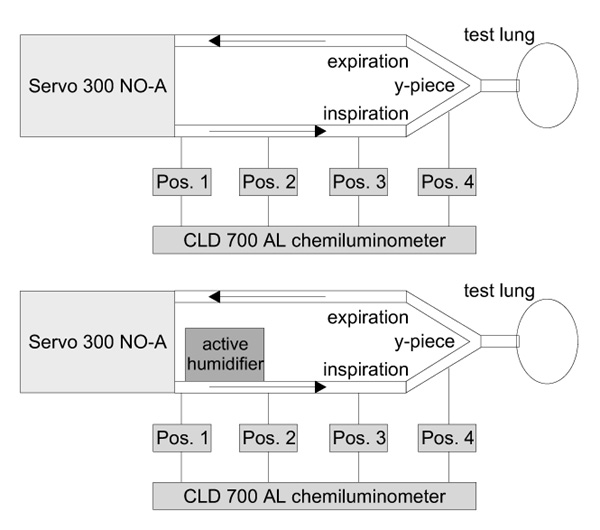
Schematic presentation of the experimental design used. At four positions (Pos. 1 to Pos. 4) along the inspiratory limb of the respiratory tubing, NO and NO2 concentrations were measured by means of chemiluminescence (CLD 700 AL chemiluminometer). The upper part of the figure demonstrates the measurement design without a humidification system. In the lower part the site of the active humidification system is indicated between Pos. 1 and Pos. 2.
Study protocol
Using the pressure controlled mode of mechanical ventilation, NO was administered in increasing doses of 0.1, 1, 10 and 100 ppm into an FiO2 of 0.21, without any humidifier mounted into the system. Each NO concentration was administered for 10min before the first measurement was taken. NO/NO2 was measured at each position (Pos. 1–4) by chemiluminescence for at least 2 min to obtain stable values.
To investigate the effect of increasing O2 concentrations the same set of measurements was then repeated for an FiO2 of 0.5 and 1.0.
To investigate the effect of additional volume due to the humidification system, the same set of measurements for all NO concentrations and all FiO2 values was obtained with an active humidification system (Concha Therm III with Aerodyne humidification column, Kendall, Neustadt, Germany) mounted into the respiratory tubing between Pos. 1 and Pos. 2 (Fig 1). In order to discriminate between the possible effect of the additional volume alone and a possible reaction of NO with water in the humidification system, all NO concentrations at all FiO2 values were administered when the heating column of the humidifier was empty and not active and repeated for a water-filled heating column.
Data analysis
Data for NO and NO2 concentrations are given for each individual set of measurements, in other words for each NO dose, for each FiO2, for the setup without humidification system (nohum), and for the setup including the inactive humidification system (inacthum) as well as for the active humidification system (acthum) in place. NO measurements are presented as percentages of the NO concentration set on the respirator. NO2 concentrations are given as absolute values (ppm). To compare the NO concentrations at the different positions and for the different setups, data for all FiO2 values and NO concentrations from 1 to 100 ppm were averaged and tested by means of the paired students t-test. Data in figures are given as mean ± standard deviation.
Results
The individual measurements of NO concentrations at the four different positions for the different FiO2 values and for the different setups concerning the humidification system are shown in Figure 2. We found a sharp decline for all NO concentrations between Pos. 1 and Pos. 2 that obviously was not influenced by the FiO2. For the setup with an inactive or without humidification system, this finding was strongly influenced by the high NO values at Pos. 1 for 0.1 ppm NO when expressed as a percentage of the adjusted NO dose. Therefore, the values for 0.1 ppm NO were excluded from the statistical analysis of mean values, which is shown in Figure 3. For all setups, a significantly lower NO concentration was found at Pos. 2–4 when compared to Pos. 1. The differences for the NO values between Pos. 1 and 2 as well as between Pos. 1 and 4 are shown in Figure 4. Again, for this analysis all NO measurements except for 0.1 ppm NO were averaged for the different FiO2 settings. The difference between Pos. 1 and 2 was significantly less pronounced when the inactive or no humidification system were used.
Figure 2.
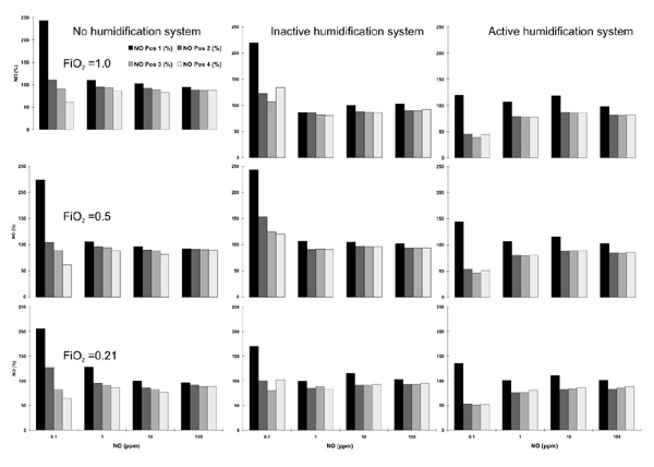
Individual NO measurements for the different NO concentrations set (x-axis, NO) and the different FiO2 values as well as the different circuit setups. The NO concentrations are expressed as a percentage of the set NO concentration (y-axis). Each line of figures represents the different settings for FiO2. Each column of figures represents the different setups for the heating system.
Figure 3.
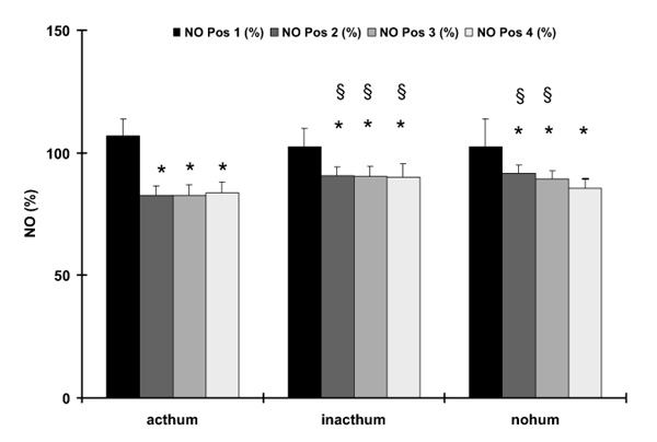
Nitric oxide (NO) concentrations as a percentage of the adjusted NO dose (y-axis) for the different setups of the heating system (x-axis). The different bars reflect the different measurement positions (see Fig 1). Data are given as mean± standard deviation. *P < 0.05, compared to pos.1 for a given setup; §P < 0.05, compared to the active humidification system (acthum) for a given position, inacthum, Inactive humidification system; nohum, no humidification system.
Figure 4.
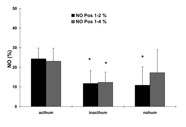
Differences in nitric oxide (NO) concentrations between different positions as a percentage of the adjusted NO dose (y-axis) for the different setups of the heating system (x-axis). The different bars reflect the different measurement positions (see Fig 1). Data are given as mean ± standard deviation. *P < 0.05, compared to the active humidification system (acthum). inacthum, inactive humidification system; nohum, no humidification system.
The corresponding NO2 concentrations are shown in Figure 5, again as individual measurements for all FiO2 values and for the different setups of the humidification system.
Figure 5.
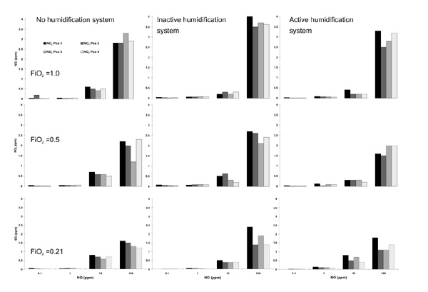
Individual nitrix dioxide (NO2) measurements in parts per million (ppm, y-axis) for the different nitric oxide (NO) concentrations adjusted (x-axis, NO) and the different FiO2 values as well as the different circuit setups. Each line of figures represents the different settings for FiO2. Each column of figures represents the different setups for the heating system.
Discussion
The most obvious conclusion from the data is that a significant variation of the NO concentrations can be found along the inspiratory limb of the breathing system even when a device to administer NO proportional to inspiratory flow, such as the Servo 300 NO-A, is used. The highest NO concentrations were found immediately behind the respirator outlet with a sharp decline to fairly stable values in the more distal parts of the respiratory tubing. Although this observation could be generally made for all NO concentrations (0.1–100 ppm) and for all different heating system setups, the magnitude of this decrease in NO along the inspiratory limb was dependent on the presence of an active humidification system.
This pattern of inspiratory NO concentrations might be explained in two different ways. The rather high NO concentrations adjacent to the inspiratory outlet might be attributed to incomplete gas mixing inside the ventilator which could result in potentially higher measured NO values than those set. Alternatively, the sharp decline between Pos. 1 and Pos. 2 might be explained by a rapid reaction of NO in between both points of measurement so that the actual amount of NO decreased. Our data suggest that both possible mechanisms may play a role.
The observation that NO decreases significantly between Pos. 1 and Pos. 2 even when no humidification system is present between those points might suggest that incomplete gas mixing inside the small internal volume of the respirator is responsible for that decline. Since no further changes in NO concentration along the inspiratory limb of the tubing could be observed distal to Pos. 2, it can be concluded that the small distance between the respirators outlet and the measurement at Pos. 2 is sufficient to achieve a complete gas mixing. Fluctuations of NO concentrations have been shown for continuous flow delivery of NO into the inspiratory circuit of a phasic-flow ventilator [15]. These fluctuations could have been minimized by using a mixing chamber. A study by Mourgeon et al [17] showed that sequential NO delivery during controlled ventilation with constant flow resulted in more stable NO concentrations than continuous NO delivery. However, when pressure support ventilation was used even sequential NO delivery did not provide stable NO concentrations [17]. In accordance with these findings, an explanation for the fluctuations between Pos. 1 and Pos. 2 in our study might be that, during pressure-controlled ventilation, a decelerating flow pattern results which cannot be exactly followed by the mass flow controller of the NO delivery device. As a result, a small asynchrony between ventilator flow and NO flow would explain the non-homogeneous gas mixing at Pos. 1.
However, the comparison between the different setups for the heating system suggests that a form of reaction of NO takes place between Pos. 1 and Pos. 2, resulting in a decreased amount of NO at Pos. 2 in the presence of water. As shown in Figure 3, the NO concentrations at the positions distal to Pos. 1 were significantly higher for the setups including no or an inactive humidification system, when compared to the active water-filled heating column. Since inclusion of the inactive heating column in between Pos. 1 and Pos. 2 did not change NO at Pos. 2 compared to the setup without the humidification system, it might be concluded that the additional mixing volume of the heating column as such does not play an important role for the NO concentration. In contrast, for the water-filled column, the difference between NO concentrations at Pos. 1 and Pos. 2 is significantly higher (Fig 4), which might indicate that NO reacts in the aqueous phase or at the gaseous-aqueous interface of the humidification system. Since NO is a very reactive chemical compound, a variety of potential reactions could be responsible for the observed decrease of NO in the active heating column [9,10]. NO reacts with O2 in sequence with the end products HNO2 and HNO3 which dissolves into NO2- and NO3 + H+. NO2 formation should be increased according to the kinetics of this reaction with higher concentrations of NO and O2 and a longer contact time between NO and O2 [14] which results from the additional gas volume of the heating column. This hypothesis is supported by the NO2 measurements that show higher NO2 levels for a given NO and FiO2 when the inactive humidification system is compared to the setup without a heating column. However, since this type of reaction alone does not explain the differing findings for the active and the inactive heating system, a second type of reaction might take place preferentially at the gas–liquid interface or in the aqueous phase of the water-filled column. This second reaction type might be a further reaction of NO with NO2 which produces N2O3 dissolving again into HNO2 in the presence of H2O [10]. With this second reaction, the further consumption of NO in the water-filled heating system could be explained as easily as the relatively lower NO2 values at Pos. 2 for the active system when compared to the inactive heating column (Fig 5) as NO2 will also be decreased by this reaction. NO2 increases in the more distal parts of the inspiratory tubing probably as a result of the well known oxidation of NO to NO2. Studies measuring further compounds of the above mentioned reactions for different ventilator settings should clarify their importance for NO delivery.
In recent studies, the importance of measuring with fast response time chemiluminescence machines has been shown to assess the true breath-by-breath variability of NO delivery systems [15,17,18]. In this study, we used a chemiluminescence machine with a rather slow response time. Therefore, we did not measure breath-by-breath fluctuations of the inspired NO or even fluctuations within one breath but instead mean NO and NO2concentrations for the different positions along the inspiratory tubing. This is clearly a drawback of the measurement device we used as we cannot rule out that faster fluctuations of NO might have occurred. However, there was a clear pattern even for these slow NO fluctuations depending on the presence of an active heating device.
In summary, we conclude that significant variations of NO concentrations occur along the inspiratory limb of the respiratory tubing during inhalation of NO from 0.1 to 100 ppm using the Servo 300 NO-A for NO delivery during pressure-controlled ventilation. The major part of these fluctuations occurs in the first 30 cm of the tubing after the inspiratory outlet of the respirator. These fluctuations are due to incomplete gas mixing in the small internal volume of the respirator. Furthermore, the chemical reaction and dissolving of NO in the aqueous phase of an active heating system may play a major role in the sharp decrease in NO concentrations across the humidification and heating system. Since these data have been obtained in a laboratory study, further clinical studies are needed to clarify whether this phenomenon is clinically important. However, the presented data emphasize that the NO and NO2 concentrations should be measured as distally as possible in the inspiratory limb of the system to get the best estimate of the real inhaled concentration. Furthermore, one should be aware that the inclusion of an active heating and humidification system into the respiratory tubing alters the administered NO concentrations. Finally, it could be speculated that, along the humid atmosphere of the more distal parts of the respiratory system of the patient, further NO is consumed by chemical reaction leading to a decrease in the efficient NO concentration at the site of action which is the alveolo–capillary interface.
Acknowledgments
Acknowledgment
We thank Margit Baum and Dirk Pahl for their excellent technical assistance in performing the experiments.
References
- Frostell C, Fratacci WD, Wain JC, Jones R, Zapol WM. Inhaled nitric oxide. A selective pulmonary vasodilator reversing hypoxic pulmonary vasoconstriction. Circulation. 1991;83:2038–2047. doi: 10.1161/01.cir.83.6.2038. [DOI] [PubMed] [Google Scholar]
- Frostell CG, Blomqvist H, Hedenstierna G, Lundberg J, Zapol WM. Inhaled nitric oxide selectively reverses human hypoxic pulmonary vasoconstriction without causing systemic vasodilation. Anesthesiology. 1993;78:427–435. doi: 10.1097/00000542-199303000-00005. [DOI] [PubMed] [Google Scholar]
- Pepke-Zaba J, Higenbottam TW, Dinh-Xuanh AT, Stone D, Wallwork J. Inhaled nitric oxide as a cause of selective pulmonary vasodilation in pulmonary hypertension. Lancet. 1991;338:1173–1174. doi: 10.1016/0140-6736(91)92033-x. [DOI] [PubMed] [Google Scholar]
- Pison U, Lopez FA, Heidelmeyer CF, Rossaint R, Falke K. Inhaled nitric oxide selectively reverses hypoxic pulmonary vasoconstriction without impairing pulmonary gas exchange. J Appl Physiol. 1993;74:1287–1292. doi: 10.1152/jappl.1993.74.3.1287. [DOI] [PubMed] [Google Scholar]
- Kinsella JP, Neish SR, Shaffer E, Abman SH. Low-dose inhalational nitric oxide in persistent pulmonary hypertension of the newborn. Lancet. 1992;340:819–820. doi: 10.1016/0140-6736(92)92687-b. [DOI] [PubMed] [Google Scholar]
- Roberts JD, Polander DM, Lang P, Zapol WM. Inhaled nitric oxide in persistent pulmonary hypertension of the newborn. Lancet. 1992;340:818–819. doi: 10.1016/0140-6736(92)92686-a. [DOI] [PubMed] [Google Scholar]
- Berner M, Beghetti M, Ricou B, Rouge JC, Pretre R, Friedli B. Relief of severe pulmonary hypertension after closure of a large ventricular septic defect using low dose inhaled nitric oxide. . Intensive Care Med. 1993;19:75–77. doi: 10.1007/BF01708365. [DOI] [PubMed] [Google Scholar]
- Sellden H, Winberg P, Gustafsson LE, Lundell B, Böök K, Frostell CG. Inhalation of nitric oxide reduced pulmonary hypertension after cardiac surgery in a 3.2-kg infant. Anesthesiology. 1993;78:577–580. doi: 10.1097/00000542-199303000-00021. [DOI] [PubMed] [Google Scholar]
- Austin AT. The chemistry of the higher oxides of nitrogen as related to the manufacture, storage and administration of nitrous oxide. . Br J Anaesth. 1967;39:345–350. doi: 10.1093/bja/39.5.345. [DOI] [PubMed] [Google Scholar]
- Gaston B, Drazen JM, Loscalzo J, Stamler JS. The biology of nitrogen oxides in the airways. Am J Respir Crit Care Med. 1994;149:538–551. doi: 10.1164/ajrccm.149.2.7508323. [DOI] [PubMed] [Google Scholar]
- Rossaint R, Falke KJ, Lopez F, Slama K, Pison U, Zapol WM. Inhaled nitric oxide in adult respiratory distress syndrome. . N Engl J Med. 1993;328:399–405. doi: 10.1056/NEJM199302113280605. [DOI] [PubMed] [Google Scholar]
- Stavert DM, Lehnert BE. Nitric oxide and nitrogen dioxide as inducers of acute pulmonary injury when inhaled at relatively high concentrations for brief periods. Inhalation Toxicology. 1990;2:53–67. [Google Scholar]
- Rasmussen TR, Kjaergaard SK, Tarp U, Pedersen OF. Delayed effects of NO2 exposure on alveolar permeability and glutathione peroxidase in healthy humans. Am Rev Respir Dis. 1992;146:654–659. doi: 10.1164/ajrccm/146.3.654. [DOI] [PubMed] [Google Scholar]
- Foubert L, Fleming B, Latimer R, Jonas M, Oduro A, Borland C, Higen-bottam T. Safety guidelines for use of nitric oxide. . Lancet. 1992;339:1615–1616. doi: 10.1016/0140-6736(92)91886-d. [DOI] [PubMed] [Google Scholar]
- Sydow M, Bristow F, Zinserling J, Allen SJ. Variation of nitric oxide concentration during inspiration. Crit Care Med. 1997;25:365–371. doi: 10.1097/00003246-199702000-00028. [DOI] [PubMed] [Google Scholar]
- Kuhlen R, Busch T, Kaisers U, Gerlach H, Pappert D, Falke K, Ros-saint R. Evaluation of two prototypes for inhalation of nitric oxide during mechanical ventilation with different tidal volumes. . Clinical Intensive Care. 1997;8:171–177. [Google Scholar]
- Mourgeon P, Gallart R, Umamaheswara Rao GS, et al. Distribution of inhaled nitric oxide during sequential and continuous administration into the inspiratory limb of the ventilator. . Intensive Care Med. 1997;23:849–858. doi: 10.1007/s001340050421. [DOI] [PubMed] [Google Scholar]
- Imanaka H, Hess D, Kirmse M, et al. Inaccuracies of nitric oxide delivery systems during adult mechanical ventilation. . Anesthesiology. 1997;86:676–688. doi: 10.1097/00000542-199703000-00021. [DOI] [PubMed] [Google Scholar]


