Abstract
Atherosclerosis at the carotid bifurcation is a major risk factor for stroke. As mechanical forces may impact lesion stability, finite element studies have been conducted on models of diseased vessels to elucidate the effects of lesion characteristics on the stresses within plaque materials. It is hoped that patient-specific biomechanical analyses may serve clinically to assess the rupture potential for any particular lesion, allowing better stratification of patients into the most appropriate treatments. Due to a sparsity of in vivo plaque rupture data, the relationship between various mechanical descriptors such as stresses or strains and rupture vulnerability is incompletely known, and the patient-specific utility of biomechanical analyses is unclear. In this article, we present a comparison between carotid atheroma rupture observed in vivo and the plaque stress distribution from fluid–structure interaction analysis based on pre-rupture medical imaging. The effects of image resolution are explored and the calculated stress fields are shown to vary by as much as 50% with sub-pixel geometric uncertainty. Within these bounds, we find a region of pronounced elevation in stress within the fibrous plaque layer of the lesion with a location and extent corresponding to that of the observed site of plaque rupture.
Keywords: Patient-specific, Vulnerable plaque, Atherosclerosis, Image-based
Introduction
Atherosclerotic plaque at the bifurcation of the extracranial carotid arteries is a major risk factor for stroke. Plaque erosion and rupture are known to be the underlying causes of many devastating acute coronary and cerebrovascular events.3,4,48 Rupture of atheroma at the carotid bifurcation can lead to shedding of embolic material either from the vessel wall or from thombi that form on the thrombogenic ruptured plaque surface. This thromboembolic material can then travel distally to the brain where it can lodge in vessels, depriving that vascular territory of blood supply thereby causing neurological symptoms. Furthermore, the presence of an irregular or cratered plaque surface, termed an ulcerated plaque, is known to increase the risk of a subsequent neurologic event, presumably from additional thrombo-embolic material that is generated and shed from the slowly rotating blood pool within the ulceration. While these vulnerable plaques generally experience an active inflammatory process and progress with strong modulation from the local biochemical environment, mechanical forces are also of importance. The composition and distribution of material in the atheroma lining the vessel wall reflects the stabilizing and destabilizing biochemical processes that determine vessel remodeling and progressive tissue damage. Rupture, then, is a mechanical process in which local stresses exceed material strengths.
2D and 3D patient-specific finite element models of diseased vessels have been used to investigate the mechanics of atherosclerotic vessels under physiologic and supraphysiologic load, such as that experienced during an angioplasty procedure.5,11,15,18,23,28,43,45 Many studies have succeeded in revealing the complexities of diseased vessel mechanics, and have made comparative analyses of various lesion types in an attempt to understand how plaque features influence vulnerability.5,41,44,45 Although not the primary purpose of most studies, a common long-term goal is the use of patient-specific biomechanical simulations of atherosclerotic vessels to assess the degree of rupture vulnerability for any particular lesion.
Such simulations are complex, however, and their patient-specific utility may be compromised by several different factors. Predictive models are based on medical imaging studies that are limited in their ability to resolve geometrical or compositional features. Material responses for plaque and vessel tissues are difficult to obtain on a patient-specific basis, and anisotropy is hard to characterize from in vivo data. Accurate knowledge of the diseased vessel’s zero-stress state cannot be derived from medical imaging, and simplifying assumptions must be made. The boundary conditions placed on the model’s vessel displacement or blood flow are often rough approximations of the in vivo situation. Additionally, the relationship between various mechanical descriptors such as stresses or strains and rupture vulnerability is incompletely known, and may not be universal. The breadth and severity of these challenges make it difficult to assess the predictive capacity of patient-specific models of rupture potential in atherosclerotic vessels.
An attractive approach for validating the predictive ability of such analyses is to assess, in cases where plaque ulceration is noted in a previously unruptured plaque, whether the location of that ulceration corresponds to the location identified in modeling as that most vulnerable to rupture. Unfortunately, data on in vivo plaque rupture, under normal physiologic conditions, is sparse. Patients with carotid atherosclerosis who have undergone an imaging study at a time when they have not experienced any plaque disruption do not necessarily progress to rupture, and if they do, the yearly rupture rate is estimated to be less than 1%. Additionally, the availability and demonstrated success of carotid endarterectomy limits the extent to which patients with advanced carotid disease are followed.33,34
In vivo observation of the formation of an ulceration in a previously smooth plaque could provide a proving ground for the sophisticated simulations currently possible, allowing a more complete understanding not only of plaque rupture but also of the assumptions and limitations of the modeling effort. In this article, we present a 3D fluid–structure interaction (FSI) analysis of an atherosclerotic carotid bifurcation based upon pre-rupture imaging data with available post-rupture imaging information. The predicted stress field within the diseased artery wall is examined within the neighborhood of known plaque rupture, and is compared to the location and extent of ulceration as determined by a post-rupture medical imaging study. This work tests the maximal local stress hypothesis,44 in which extreme local stress concentrations are suspected to directly cause plaque rupture.
Because of the recent wealth of work in carotid plaque biomechanics,19,26–28,40,46 we believe that more cases like this one will be found in the clinical workload and examined using similar numerical methods. For this reason, we have built our models using methods that can be quickly and easily employed for highly complex geometries, material distributions, and boundary conditions. Patient-specific data are used whenever possible in this approach.
This article will first describe our approach to patient-specific modeling of atherosclerotic arteries. Next, we will present results from our stress analysis of a carotid plaque that is known to have undergone rupture. We will then explore the effects of modeling uncertainty introduced by imaging and image segmentation imprecision of sub-pixel (<0.5 mm) magnitude. Particular attention will be paid to the influence of modeling uncertainty on the predicted stress field in the region where the plaque is known to have ruptured.
Materials and Methods
Imaging and Geometric Model
The analysis presented here is based on a multidetector computed tomography angiography (MDCTA) study of an 83 y/o male using the following acquisition protocol: spiral mode; slice thickness 1.25 mm, slice acquisition interval 1 mm, pitch 1.375:1; 120 kVp, 240 mAs; intravenous administration of 70 mL of iodinated contrast material at a rate of 4–5 mL per second, with an acquisition delay calculated from a test bolus ranging from 14 to 29 s. Data acquisition were performed from the origin of the aortic arch branch vessels to the vertex, with an in-plane resolution of 0.5 mm × 0.5 mm.
As seen in Fig. 1a, the internal carotid artery (ICA) had a large plaque burden at baseline, with the image intensities suggesting that the plaque contains a large lipid core. At baseline, the ICA was roughly 85% stenotic by area at slice 2 in Fig. 1a (in a circular lumen this would correspond to a diameter stenosis of 61%). The patient was admitted for a possible transient ischemic attack 8 months after the baseline imaging study, and the CTA study shown in Fig. 1b revealed that a portion of the ICA plaque had ruptured and plaque contents had emptied into the circulation. From the CTA images, it appears that the plaque ruptured over a segment of ICA 6.25 mm in length located 6.25 mm superior to the bifurcation. The rupture was located on the posterior aspect of the lumen surface, and circulating blood “tunneled” into the plaque core about 3.75 mm inferior to the first imaging slice demonstrating plaque failure.
Figure 1.
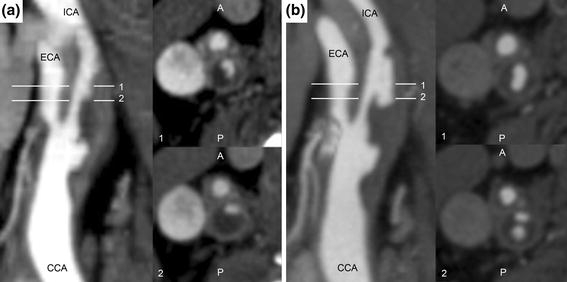
CTA studies showing lumen geometry in the longitudinal plane (left) and transverse to the lumen for slices 1 and 2 (right) at (a) baseline, without plaque rupture distal to the bifurcation. Note the irregular lumen geometry proximal to the bifurcation, suggesting existing ulceration of common carotid artery plaque. (b) Eight-month follow-up. Slice 1 shows increased lumen area in the internal carotid artery consistent with plaque rupture, while slice 2 shows that a portion of the plaque core inferior to the rupture location has emptied after fibrous cap failure
To establish a computational geometry for our study, the vessel lumen and lipid pools were segmented from the images based on Hounsfield unit using a 3D level-set active contour algorithm implemented in ITK-SNAP 1.80.53 Each “snake” was initialized in several locations based on image intensity and local features. The image intensities corresponding to different materials were based on results from de Weert et al.8 and from image features, and are provided in Table 1.
Table 1.
Hounsfield unit ranges used for segmentation
| Material | Hounsfield unit range |
|---|---|
| Fibrous tissue (vessel wall, fibrous plaque) | 65–170 |
| Lipid pool | 65 and below |
| Contrast-enhanced circulating blood | 170 and above |
Before implementation of the active contour algorithm, images were re-sampled from 512 × 512 to 1024 × 1024 in-plane, and from a slice thickness of 1.25 mm to a thickness of 0.3125 mm. The image series was thus represented in 3-dimensions as a set of voxels far more isotropic than the original acquisition, allowing for a more accurate segmentation with the 3D snake algorithm.
Perivascular structures often have image intensities similar to that of fibrous and muscular tissues found in diseased arteries. For this reason, the outer boundary of the vessel wall was segmented manually based on image intensity and local vessel wall curvature in the coronal, sagittal, and axial planes. The consideration of vessel wall curvature was secondary to image intensity, but was included to assure that the outer vessel wall appeared smooth as it does upon exposure during carotid endarterectomy.
Careful attention was paid so that the segmentation did not contain lipid–lumen deviations less than two pixel-widths. In this way, resampling of the data did not create regions of fibrous cap thinner than could be resolved with the original clinical imaging employed. If necessary, a one pixel-width lipid–lumen deviation was increased by an additional pixel-width by eliminating the encroaching lipid pixel. This was done only a handful of times throughout the entire dataset, and would serve to reduce calculated fibrous cap stress if it had any effect at all.
Because the radio-opacities of fibrous plaque and healthy vessel wall are so similar, one cannot accurately distinguish between the two tissue types based on a range of Hounsfield units. In our segmentation, every pixel inside the vessel wall outer boundary that was not already designated as lipid or lumen was temporarily designated to be “fibrous tissue”. Figure 2 shows the images and the segmentations of lipid pool, lumen, and fibrous tissue. As seen in surgery and from histological examination, some portion of relatively healthy vessel media and adventitia remains surrounding the fibrous plaque, lipid pools, and vessel lumen. To account for this, the outermost 0.5 mm of fibrous tissue was re-assigned to be healthy wall tissue. The remaining fibrous tissue was assigned to be true fibrous plaque. The fibrous plaque was assumed to extend longitudinally such that all lipid pools were fully contained within fibrous plaque, healthy common carotid artery (CCA) wall thickness did not exceed 1.0 mm, and healthy ICA wall thickness did not exceed 0.5 mm. At least one pixel was left unassigned in the segmentation between the ICA and the external carotid artery (ECA) so that contact between the branches, believed to have little impact on fibrous cap stresses, could be avoided in the computational model.
Figure 2.
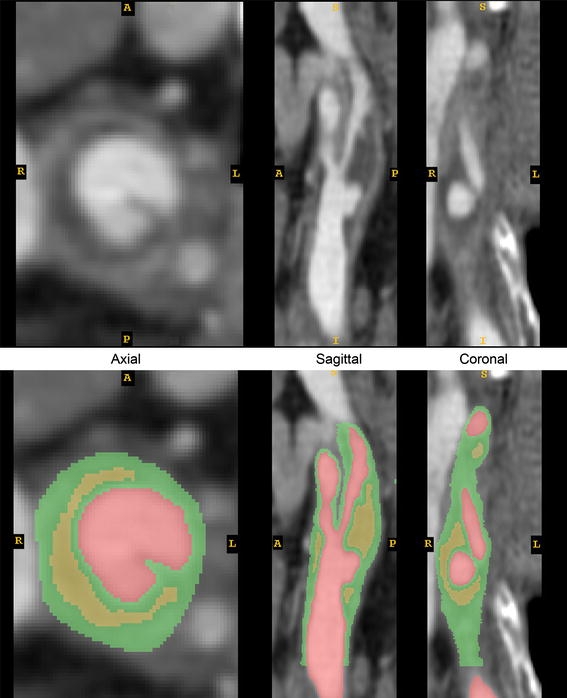
Original and segmented CTA images. Green = fibrous tissue, comprising healthy vessel wall and fibrous plaque; Red = vessel lumen; Yellow = lipid pool
The final geometric model extended from ~2.7 cm proximal to the bifurcation to ~2.7 cm distal, such that flow could be modeled with reasonable boundary conditions. The segmentation procedure resulted in a geometry where fibrous plaque begins 2 cm proximal to the bifurcation and ends 0.44 and 2.4 cm distal to the bifurcation in the ECA and ICA, respectively. Surface representations of the vessel lumen, fibrous plaque outer boundary, lipids, and outer vessel wall are shown in Fig. 3. Representative coronal images and corresponding slices through the geometric model are shown side-by-side in Fig. 4, demonstrating the distribution of fibrous plaque thickness. Details of the plaque segmentation and fibrous plaque thickness in the region of rupture, as shown in Fig. 1a, are presented in Fig. 5, where the original images, their segmentation, and the final geometric representation of the region used in the finite element model are shown.
Figure 3.
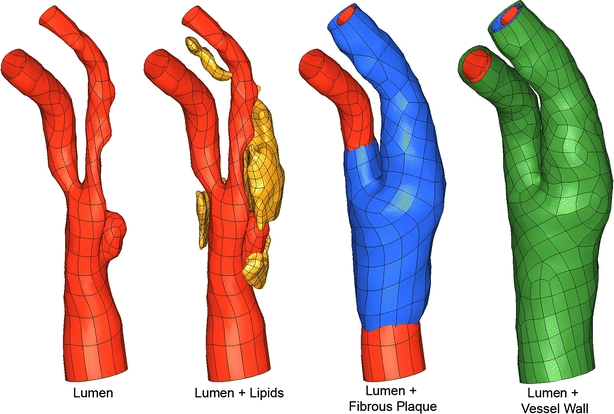
Bounding surface representations of key vessel components. Green = healthy vessel wall; Red = vessel lumen; Yellow = lipid pool; Blue = fibrous plaque
Figure 4.
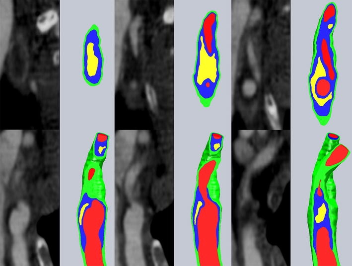
Coronal CTA image slices and corresponding slices through the reconstructed geometrical model. Green = healthy vessel wall; Red = vessel lumen; Yellow = lipid pool; Blue = fibrous plaque
Figure 5.
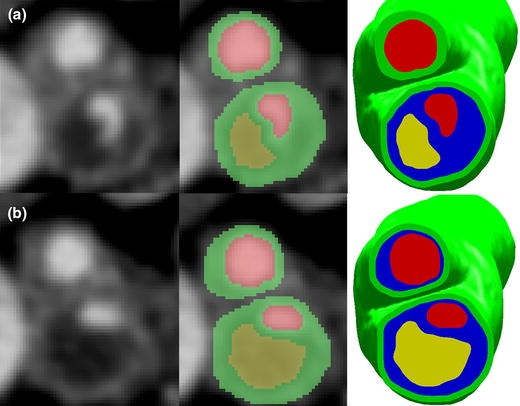
Axial slices at level 1 and 2 as shown in Fig. 1. (a) Raw image (left), segmented image (center), final geometry with fibrous plaque (right) for level 1. (b) Raw image (left), segmented image (center), final geometry with fibrous plaque (right) for level 2. Green = healthy vessel wall; Red = vessel lumen; Yellow = lipid pool; Blue = fibrous plaque. Note that in the segmented images, fibrous plaque boundaries have not yet been established
Material Descriptions
For the flow rates considered and geometry studied, it is unlikely that a non-Newtonian constitutive formulation for blood would alter the flow field solution appreciably.25 For this reason, blood was treated as an incompressible Newtonian fluid, with dynamic viscosity μ = 0.0035 Pa s and density of 1060 kg/m3.
Vessel wall, fibrous plaque, and lipids were modeled as nearly incompressible, isotropic, nonlinear, hyperelastic materials using the Demiray-type strain energy density function
 |
1 |
where I 1 is the first invariant of the Cauchy-Green deformation tensor and D 1 and D 2 are constants determined experimentally for each tissue type.10 The product D 1 D 2 is proportional to the elastic modulus of the material at zero strain, while D 2 relates to the strain-stiffening behavior typical of collagenous biological materials. Material constants, taken from previously published studies, are listed for the three tissue types in Table 2.5,10,29,31
Table 2.
Material parameters for vessel wall, fibrous plaque, and lipid pool
| Material | D 1 (Pa) | D 2 |
|---|---|---|
| Vessel wall | 2644.7 | 8.365 |
| Fibrous plaque | 5105.3 | 13 |
| Lipid | 50 | 5 |
Two-Stage Solution Method
Because accurate resolution of the stress field in such a complex geometry would require an impractically large element count, a two-stage approach was taken to model the diseased artery. The full details of this modeling strategy are presented elsewhere,24 and only the essential features will be discussed here. Key steps in the finite element model definition and two-stage solution are shown in Fig. 6.
Figure 6.
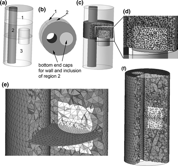
Outline of the 2-stage method used in this analysis, shown for a simple geometry. (a) A schematic artery with eccentric lumen and small cylindrical inclusion. Intersections of the geometry and two truncation planes are shown by the curves separating region 2 from regions 1 and 3. Region 2 is the region of interest. (b) Regions 1 and 2 shown, with bottom end caps for “wall” and inclusion of region of interest shown. (c) Fine mesh within region of interest used for second stage of two-stage method. (d) Magnified display of region of interest. (e) Bottom plane of region of interest, finely meshed in (c), shown with conforming coarse mesh used in the same region during stage 1 of two stage approach. (f) Full-domain coarse mesh used in stage 1
First, “truncation planes” are used to divide the full domain into segments, one of which is the region of interest where accurate stress predictions are desired (Fig. 6a). At the planar interfaces between the region of interest and the remaining geometry, a set of “end cap” faces are constructed so that each region and the end caps form air-tight geometrical objects (Fig. 6b). The region of interest is discretized using a high-resolution mesh capable of accurately resolving stresses (Figs. 6c, 6d). The discretization on the end caps is saved, and used as a portion of the boundary discretization for a full-domain, coarse-mesh model (Fig. 6e). Here, the entire domain is meshed just finely enough to accurately represent geometric features and solve for displacements. A time-dependent FSI simulation is run on the full-domain, coarse-mesh model (Fig. 6f), solving for the fluid and solid dynamics and giving an estimate of solid stress patterns.
The nodal displacements from the time-dependent problem are saved at the boundaries of the region of interest. Fluid velocities are saved at the inlet to the region of the interest, and average fluid pressure is saved at the outlet. The solutions from the coarse model at the planar inlet and outlet are then used as boundary conditions in the secondary, fine-mesh model of the region of interest so that stress fields may be accurately resolved in the diseased artery wall. By using the same end cap meshes in the fine-mesh model, nodal solutions can be passed directly from the coarse model to the finely meshed model. The end caps are constructed as level planes for use in the first stage simulation for easy reference, but their non-planar shape during the second stage solution is fully determined by the results of the first stage. No assumptions on mesh displacement or planarity are made at the end caps during either stage of the solution process.
Mesh Generation
The use of the two-stage approach dictates that the coarse mesh conforms to the region of interest’s fine mesh at the truncation planes, which necessitates a careful geometry preparation and meshing scheme. After formation of plaque and vessel component end caps, contiguous surfaces are forced to use the same bounding curves at the truncation planes so that their discretizations will naturally conform. Each surface, inside and outside the region of interest, is meshed with three node triangles and the end caps are also meshed. By using the appropriate sets of surface meshes as input, conforming 4-node tetrahedral volume meshes are made for each vessel and plaque component. The entire solid domain mesh is then converted to 10-node tetrahedra employing a mixed finite element formulation. By converting the linear element meshes to higher order elements, mid-side nodes can be placed at the midpoint of the element edge and element quality is predictable and very good over the highly complex geometry. The fine-mesh model is meshed with more accurate 11-node mixed-formulation tetrahedra for the solid domain, with an element density high enough to accurately solve for the material stress field. Because the solution times for the computational fluid dynamics (CFD) portion of the iteratively coupled FSI problem are much lower than those of the solid domain, an accurate fluid mesh of several hundred thousand linear tetrahedra was used. Examples of the fluid mesh and solid meshes, made using Hypermesh (Altair Engineering, Troy, MI), are shown in Fig. 7.
Figure 7.
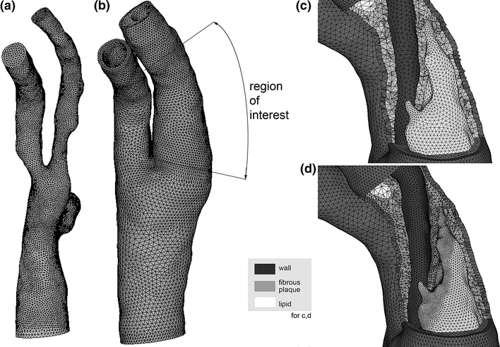
Computational meshes. (a) Fluid domain. (b) Solid mesh used for 1st stage solution. The region of interest covers the rupture location in the ICA. (c) Coarse mesh cutaway in region of interest for 1st stage solution. (d) Fine mesh cutaway in region of interest (shown with remainder of model) used for 2nd stage solution. Note the dramatic increase in element count throughout the fibrous plaque layer
Mesh independence studies were conducted for each stage of the solution. In the first stage of the computation, the goal is to accurately resolve solid displacements, which can be achieved at a solid element density lower than that required to resolve a highly converged stress field. A segment of the region of interest was meshed multiple times with increasing element density, and lumen and outer wall boundary circumferences were measured at multiple longitudinal positions before and after lumen pressurization. A six-fold increase in element density from the coarsest to finest mesh was shown to have a negligible effect (less that 1%) on the measured circumferences and out-of-plane displacements. To assure displacement accuracy throughout the entire domain, an intermediate mesh density was used in the first stage computation. To determine an element density suitable for the second stage solution, the region of interest was meshed three times with increasing element density. Element counts for the three models are provided in Table 3. Calculated first principal stresses within the fibrous plaque layer were divided into quartiles Q1–Q4, with Q1 being the smallest stresses. The minimum, maximum, and average of each quartile converged to within 5% from the medium mesh to the finest mesh, and the medium mesh density was used for the second stage solution.
Table 3.
Element counts for meshes used in stress resolution tests
| Test mesh | Total solid element count | Fibrous plaque elements |
|---|---|---|
| Coarse mesh | 103,148 | 67,191 |
| Medium mesh | 173,570 | 123,594 |
| Fine mesh | 305,580 | 219,116 |
Solid Boundary Conditions
In FSI problems of arterial structures, the solid domain is constrained in some way at the inlet(s) and outlet(s) to prohibit rigid body motion. In our models, we define local cylindrical coordinate systems at the inlet and outlets of the carotid bifurcation with  being in the direction of the lumen centerline. All nodes on the inlet and outlet planes are constrained in the local
  direction. To prevent possible rotation of the entire model, which could increase convergence time, one edge of one element is fully constrained at the inlet and outlets.
Flow Boundary Conditions
While the stresses felt by the vessel and plaque tissues are mainly a result of systemic arterial pressure, with flow-related shear stresses often being orders of magnitude smaller, flow shear stress is sensed by the endothelium and could play some role in the vulnerability of atherosclerotic lesions. Time-dependent flow boundary conditions were generated from an ultrasound study of the same patient made on the same day as the baseline CTA study. The Doppler ultrasound data provided peak systolic and end diastolic velocities at the proximal CCA and distal ICA. Under the assumption that the maximum velocity corresponds to the centerline velocity, and that the profiles were parabolic at peak systole, a set of flow rate waveforms measured with phase-contrast MRI for another patient with similar ICA stenosis were scaled appropriately and used here. Flow rates for the CCA and ICA are shown in Fig. 8.
Figure 8.
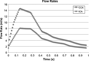
Flow rates at the CCA inlet and ICA outlet. Flow rates were used to generate time-dependent Womersley-type velocity profiles
The vessel lumen is approximately circular at the CCA inlet and ICA outlet, and an equivalent circular radius r c was calculated for each. An in-house code developed in MatLab (The Mathworks, Natick, MA) was used to calculate time-dependant Womersley profiles based on the flow rate waveforms and the equivalent radii at the CCA and ICA. The use of a Womersley profile at the model inlet was shown by Moyle et al.35 to be an acceptable approximation for simulations of carotid bifurcation flow. The circular Womersley profiles were linearly mapped to the inlet (outlet) nodes, with all nodes at the wall boundary being assigned a null velocity. Unfortunately, pressure data was not available for this patient and realistic but generic pressure conditions were used. The outlet of the ECA in our model is still within the conducting circulation, and the pressure therefore fluctuates significantly throughout the cardiac cycle. The fluctuation is only greatly reduced much further downstream in the vasculature, and so specifying a static pressure at the ECA is not appropriate. The simplest assumption to make without introducing retrograde flow or spurious oscillations in CCA flow was to assign a pressure waveform of the same shape as the CCA flow waveform. The waveform was scaled so that the end diastolic pressure at the ECA outlet was 80 mmHg, while the maximum pressure there was 120 mmHg. Although the pressure waveform has the same shape as the CCA flow waveform, no assumptions were made of the pressure waveform at the CCA, and the pressure-flow phase relationship was dictated entirely by the solution of the coupled FSI equations.
FSI Boundary Conditions
At the lumen surface, the fluid and solid domains must be consistent with a no-penetration, no-slip behavior. To enforce this, the following boundary conditions are placed on each domain’s FSI boundary during FSI iterations:
 |
2 |
where subscript S, f, and M denote solid, fluid, and fluid mesh (in the ALE formulation), respectively. τ is the stress tensor,  is the unit vector normal to the FSI interface,
  is the displacement of the fluid mesh, and
  ,
,  , and
, and  are the fluid velocity, mesh velocity in the ALE formulation, and solid displacement vector, respectively.
Solution Method
The relevant equations of motion for the incompressible Newtonian fluid and solid domains are
 |
3a,b |
and
 |
4 |
where ρf and ρS are fluid and solid density, p is fluid pressure, and μ is Newtonian fluid viscosity.  ,
,  , and
, and  are the fluid velocity, mesh velocity in the ALE formulation, and solid displacement vector, respectively. τ is the Cauchy stress tensor and f
B is the body force the solid experiences.
Equations (3) and (4), subject to the fluid and solid boundary conditions, FSI boundary conditions in Eq. (2) and material formulations discussed above, were solved over a cardiac cycle using the commercial finite element code ADINA (ADINDA R&D, Watertown, MA). ADINA has been used extensively to model systems exhibiting material and geometric nonlinearity, and has been successfully employed to solve arterial FSI problems.20,39,46,50,51 We use ADINA to solve the strongly coupled nonlinear fluid and solid systems of equations in an iterative manner using in-core direct sparse solvers. Flow was assumed to be laminar and was solved using a Galerkin finite element method with upwinding applied. The nonlinear fluid and solid systems of equations were solved by Newton–Raphson iteration with equilibrium iterations at each time step and each FSI update.
It should be noted that while the material stresses are accurately solved during the second stage of our two-stage process, the flow field dynamics are most accurately solved over the full domain during the first stage. The significant savings on computational time and resource requirements afforded by the two-stage solution method come at a modest cost on solution accuracy when compared to the results of a traditional one-stage solution. As shown in an earlier article that considered the same model,24 the average deviation in the two-stage computed pressure field over the region of interest was 1.5% of the pressure field computed using a single-stage solution. The passage of nodal displacement solutions from the first to second stage, with a large increase in element density, resulted in a maximum stress difference of around 5% within the region of interest, and a virtually identical stress distribution.
Effects of Imaging Imprecision
The primary structural features that correspond to increased plaque stresses are a large lipid core and a thin fibrous cap overlying the lipid core.6,30,36 To better understand the effects of an improper representation of the plaque components in this particular artery, we have run several simulations in which the geometry of a large lipid pool is modified in a manner consistent with imaging imprecision.
The partial voluming effects inherent to CT and MR imaging can lead to feature misinterpretation or inaccurate segmentation of a medical image. With in-plane resolutions on the order of 0.25–0.5 mm, current imaging modalities are susceptible to partial volume effects that could alter an image-based finite element model. An additional challenge in CT imaging is incomplete discrimination of lipid and fibrous plaque tissue. To study the effect of imaging imprecision, and how it might impact information gathered from this unique plaque dataset, we modified the luminal face of a large lipid pool (the side of the pool closest to the lumen) in this model. An adjusted luminal face of the lipid pool was generated as a constant offset surface from the original face in the direction of the local surface normal, using offsets of 0.2, 0.4, and 0.5 mm. In this way, lipid pool features were essentially preserved, and fibrous cap thickness was varied accordingly. The lipid pool geometry was only modified in the segment of the ICA containing the region of plaque rupture, as this would by far have the greatest impact on stresses there. In an effort to isolate the effects of reduced fibrous cap thickness from those of increased total lipid pool volume, only the surface of the lipid pool facing the lumen was modified. Thus, lipid volume was modestly increased without changing the entire lipid pool geometry. The volumes of the baseline and modified lipid pools within the region of interest identified in Fig. 7 are listed in Table 4.
Table 4.
Volume of lipid pool for four cases modeled
| Surface offset for lipid pool (mm) | Volume of lipid pool contained in region of interest (mm3) |
|---|---|
| 0 (Baseline geometry) | 150.19 |
| 0.2 | 171.07 |
| 0.4 | 194.09 |
| 0.5 | 206.5 |
Results
Baseline Model
The baseline model and additional models with modified lipid pool boundaries all used the same flow boundary conditions, arterial solid constraints, and two-stage solution strategy in determining the stress distribution in the region where the plaque ruptured.
A 14 mm spline curve of the ICA lumen centerline was constructed and used to define 15 planar slices along the vessel axis on which stress results were analyzed (see Fig. 9). By plotting peak stresses of each slice for the baseline and all lipid-offset cases, it was found that slices 1 and 7–10 consistently experienced the lowest stresses in the region of plaque rupture, and slices 11–15 displayed no interesting stress patterns. For this reason, stress results are only discussed for slices 2–6. As seen in Fig. 9, slices 2–6 cover the region over which lumen geometry changed most drastically post-rupture. The cut plane slices are defined with respect to the pre-rupture lumen geometry, while the post-rupture geometry is shown in transparent gray for reference. For brevity, the location on the post-rupture CTA images indicating plaque rupture will be referred to as the region of rupture, although there is no way to be certain of where the rupture was initiated.
Figure 9.
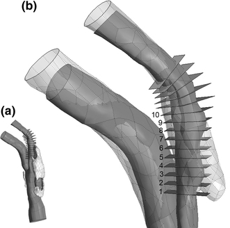
Cut planes on which first principal stress results are compared. (a) View of full lumen geometry and lipid pool with cut planes. (b) Zoom view of (a) in region of plaque rupture. Post-rupture lumen geometry shown in transparent gray. Stress results are presented for planes 1–10 only, as these cover the region of plaque rupture. The patient’s neck was positioned slightly differently for baseline and follow-up CTA studies, deforming the carotid geometry. Pre- and post-rupture lumen geometries were aligned for maximum overlap of ICA proximal and distal to the region of rupture
First principal stresses in the fibrous plaque layer, of primary interest in plaque rupture, are shown for slices 2–4 in the top panel of Fig. 10. The stress plots correspond to the time at which fibrous plaque stresses near the region of rupture were highest throughout the cardiac cycle. The outer boundary curve of the vessel wall is displayed, the lumen is indicated with “Lu”, and lipid pool is indicated with “Li”. The stress fields from the baseline model reveal stress concentrations at the intersection of the “major axis” of the roughly elliptical lumen and the fibrous plaque. In an idealized geometry with an elliptical lumen this is easily understood by considering the force balance of blood pressure and circumferential stress.22 In this case, where the lumen shape and fibrous plaque thickness are irregular, the stress field is not symmetrical across the lumen and peak stress locations are influenced substantially by local fibrous plaque thickness, lipid pool volume and proximity, and lumen curvature. With the exception of slices 3 and 4, first principal (in this geometry, very nearly equivalent to circumferential) stress peaks for slices 2–6 are located in the region of plaque rupture. At slices 3 and 4, the fibrous plaque thickness at the location of peak stress is much smaller than elsewhere in the geometry and this dominates over the effects of the lipid pool. Many finite element studies of atherosclerotic vessels have revealed that plaque lipids do not support a great deal of stress due to their relative compliance. Our results show this as well, with lipid stresses being compressive and within the range of 500–2500 Pa. Stress patterns in the vessel wall were unremarkable, with tensile stresses in the range of 0–40 kPa, and a few very small regions of weakly compressive stress.
Figure 10.
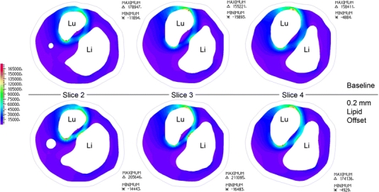
Axial “slices” through the region of interest, as shown in Fig. 9. First principal stresses are displayed for fibrous plaque layer in baseline model and model with 0.2 mm lipid surface offset. “Lu” shows the position of the lumen on each slice, “Li” shows the position of the lipid pool, and the outline of the outer vessel wall is shown for reference
Modified Lipid Pool
Due to a change in the stiffness of the diseased artery wall with different lipid pool boundaries, the pressurized lumen geometry varied slightly between different models. The effect of this difference on the converged pressure field solution was minimal, with maximum deviations from the baseline pressure field of 1.5% for the 0.2 mm offset case, 3% for the 0.4 mm offset case, and 5.4% for the 0.5 mm offset case. In each case, the largest deviations were near the boundary of the model and would not affect the wall stresses in the region of rupture appreciably.
The lower panel of Fig. 10 shows the fibrous plaque first principal stresses on slices 2–4 of the model with a lipid pool surface offset of 0.2 mm. For slice 2 the stress pattern remains largely the same and peak stresses are located in essentially the same locations as in the baseline geometry, with an average stress increase of 12.6% (std. dev. = 2.06%). The peak stress on slice 4 is now located across the lumen from its location in the baseline model, and it is now within the region of plaque rupture with a magnitude increase of 9.9% over baseline stress. At slice 3, the small decrease in fibrous plaque thickness covering the lipid core caused the peak stress location to deviate substantially from the location seen at baseline. Here, the peak stress is at the surface of the fibrous cap directly apposing the lipid core. In fact, for all slices examined, the stresses in the fibrous cap directly apposing the central portion of the lipid core (not at the lipid core shoulders) increased substantially. From the CTA data, it is clear that this location is within the region of rupture. Thus, for the model with a lipid surface offset of 0.2 mm, less than half of a pixel-width for state-of-the-art in vivo imaging, peak stress locations for each slice are consistent with the site of rupture. The first principal stress for this case at the luminal surface of fibrous plaque was plotted on the lumen geometry, and is shown in Fig. 11. The distribution of wall shear stress (WSS) is also shown for the same region, at the same cardiac phase. The first principal stress field is viewed from outside the lumen so that the results are most easily compared to the changes in lumen geometry observed post-rupture, and so that first principal stress and WSS fields are easily related. Comparing Figs. 9 and 11, it is clear that a local first principal stress concentration corresponds well to the region of plaque rupture. First principal stress concentrations outside of the region of rupture are attributed to the exceedingly thin local fibrous plaque layer, and suggest that some combination of stress magnitude and other local feature (i.e., distance from lipid core, inflammatory state, or another mechanical descriptor) may be the best predictor of rupture-risk. The WSS field shows a local minimum over the region of rupture, with local maximum shear located just proximal at the stenotic throat.
Figure 11.
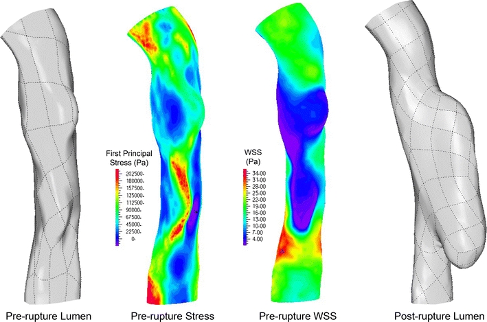
Pre-rupture lumen geometry (left), first principal stress field based on pre-rupture geometry (left center), wall shear stress distribution of pre-rupture geometry (right center), and post-rupture lumen geometry (right). The first principal stress field shown is that within the fibrous plaque layer at the lumen surface
As the luminal face of the large lipid pool was further modified to a 0.4 and 0.5 mm offset, slices 5, 6, 8, and 9 all experienced peak stresses in the fibrous cap directly apposing the central portion of the lipid core. It should be mentioned that nodal result smoothing, common in the literature for complex 3D models, should not be used across a material boundary as is commonly done. Smoothing stress results across the fibrous plaque/lipid pool boundary is inappropriate due to material differences, and effectively masks any elevated stress present at the fibrous plaque apposing the low-stress lipid pool. Conclusions drawn from these smoothed results can be dramatically different than those drawn from non-smoothed or properly smoothed nodal results. The magnitude trends for peak stresses as a function of lipid pool modification are shown for slices 1–10 in Fig. 12.
Figure 12.
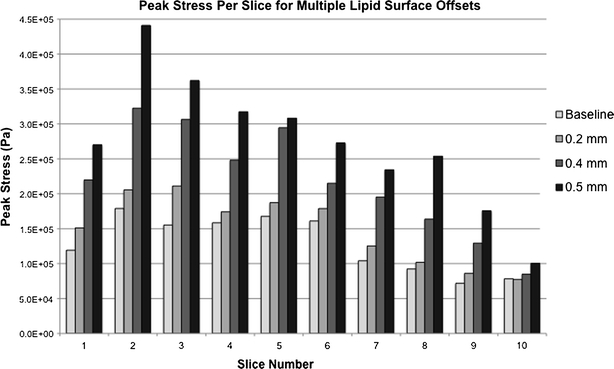
Peak stress magnitudes at slices 1–10 for models with varying lipid pool surface offsets. While slice-to-slice trends do not change qualitatively, stress magnitudes and peak stress locations at each slice change significantly
Discussion
In this work we have presented what is, to the best of our knowledge, the first image-based stress analysis of an atherosclerotic plaque based on pre-rupture imaging data where post-rupture imaging data is available for identifying the actual site and extent of rupture. We have shown that the region of plaque rupture coincides with a pronounced local elevation of first principal stress. In an effort to realistically model the mechanical environment of the heavily diseased carotid bifurcation considered, we have utilized a 3-dimensional finite element model with fully resolved plaque structures and fluid–solid interaction. These sophisticated image-based models are increasingly being used to augment the understanding of plaque mechanics provided by simpler 2D models, and models of idealized vessel and plaque geometries. It is hoped that patient-specific biomechanical models will have clinical utility in the characterization of atherosclerotic lesions, and in the optimization of individual patients’ treatment plans.
Before these models find a place in routine clinical management, however, a suitable mechanical descriptor, or a combination of multiple descriptors must be correlated to plaque rupture vulnerability. Several mechanical factors have been proposed to be relevant to the initiation of plaque rupture, drawing from both the fluid mechanics and solid mechanics of diseased vessels. While low and oscillatory flow-induced wall shear stress has long been known to influence plaque initiation, the endothelial damage caused by extreme shear stress is now suspected to contribute to rupture due to both mechanical and biological effects.12–14 Critical pressure and flow conditions in stenotic vessels have also been suspected as contributing to rupture initiation.2,42 A strong pressure drop at the throat of a stenosis can cause arterial collapse locally, most severely during peak systolic flow, altering arterial wall and plaque stresses significantly from the homeostatic norm. Among the structural mechanical factors suspected to influence plaque vulnerability, cyclic stress/strain and maximum stress stand out as likely determinants of plaque rupture. Although both descriptors are related to the stress within plaque tissues, the mechanisms by which they influence plaque destabilization differ. Cyclic stressing and deformation of plaque tissues have been shown to cause local tissue damage at stresses far less than the tissue failure strength, and thus plaque rupture is being investigated as a fatigue process.1,32,47 A more acute form of plaque rupture is thought to occur when local plaque stresses, particularly those in the fibrous cap region, exceed the tissue failure strength causing catastrophic damage. Accordingly, several studies have sought to quantify either the first principal or von Mises stresses in the fibrous caps of idealized and patient-specific lesions.6,26,30
The mechanical analyses used to explore these possible rupture mechanisms have, with exception to that by Groen et al.,14 used idealized diseased vessel geometries, artificially repaired geometries from ruptured lesions, or have used histological features, structural features, or symptom status of the patient as a surrogate for rupture. Groen et al.,14 used serial MRI data of a 67-year-old woman with pre- and post-rupture imaging studies to show that a carotid plaque ruptured in a region of locally elevated wall shear stress. The study used a rigid-wall CFD model to determine wall shear stress throughout the carotid bifurcation, and thus was incapable of resolving plaque stresses resulting from systemic pressure. Without patient-specific flow boundary conditions, only a steady-state simulation with equal normal tractions at the ICA and ECA was presented. Although these assumptions and limitations can severely affect the CFD results, the study is important because it examines a plaque known to have ruptured and the analysis is based on pre-rupture imaging data. Given the rarity of pre- and post-rupture imaging data being available for a particular patient, it is important that these cases be analyzed and interpreted with the inherent modeling limitations in mind.
The results presented here build on those of Groen et al. While we have chosen to focus on the material stresses in the region where a carotid plaque rupture occurred, the flow-induced shear stress at the diseased vessel wall is also available from our FSI model. In contrast to the results of Groen et al., our analysis shows that WSS is not elevated within the region of rupture, but is in fact at a local minimum. Just proximal to the region of rupture, in the stenotic throat of the ICA, WSS is at a local maximum. At the most distal portion of WSS elevation, there is a small lumen segment on which both WSS and first principal stress are elevated. Given the proximity of the two types of stress concentrations, and the sensitivity of WSS calculations to lumen geometry, it is difficult to conclude whether or not there truly is an “overlap” region where both first principal stress and WSS are at a local maximum. Further studies and careful sensitivity analyses should be conducted to explore the idea that a combination of elevated plaque stresses and WSS contribute to rupture potential.
While our result showing co-localization of elevated first principal stress and plaque rupture is compelling and suggests that maximum local stress might be a primary influence on plaque vulnerability, our study has a number of limitations and we therefore cannot make definitive statements about a cause of rupture. The stress field at the lumen surface shows the peak stress at a location outside the region of rupture, and other areas of stress concentration exist. Stress concentration outside of the rupture region occurs where the fibrous plaque layer is especially thin and not directly overlying the lipid pool. The fibrous plaque in these regions is roughly half as thick as that overlying the lipid pool in the region of rupture.
Other FEM studies have shown peak stresses outside of a suspected “vulnerable” region, often in a relatively healthy portion of vessel. These observations inspired the “critical site tracking” approach of Tang, in which only particular features of the stress field are used to draw conclusions about lesion vulnerability.44 We suspect that detailed regional information about the material response or ultimate tensile strength of the fibrous plaque would help to reduce the apparent stress paradox. Until such information is available, indirect measures of local tissue strength may be of some use. For instance, proteolytic activity from macrophage-expressed matrix metalloproteinases may be limited to some distance from the lipid core, suggesting that we weigh the influence of the stress-field based on location. The rapid progress in lesion-specific constitutive modeling20,21 and inflammation imaging will surely increase the realism and reliability of predictive modeling.16
Because of the computational intensity of this type of problem, only one cardiac cycle was simulated to obtain the results presented. Transient effects are often seen in flow simulations, requiring multiple cardiac cycles to be run before flow solutions are considered reliable. In our case, because the flow field and shear stress patterns were not of primary interest, these transients were ignored. Furthermore, as already mentioned, lack of detailed patient-specific flow boundary conditions required modification of conditions from another patient for use in this model. Nevertheless, the primary cause of wall stress, systemic pressure, was within physiologic range and since transient effects are thought to be of second-order importance here we believe improved modeling of these flow effects would not substantially alter our results. A more lengthy analysis should be conducted to verify this.
Most finite element analyses of atherosclerotic arteries derive the arterial and plaque geometries from a multi-sequence black-blood MRI study. The ability to manipulate soft tissue contrast in MR imaging is far greater than that of other imaging modalities, and recent work has shown that this allows accurate characterization of carotid plaques.37,38,52 Owing to relative cost and availability, however, MR studies are performed far less often for suspected cerebrovascular events than computed tomography studies, including non-contrast, angiographic (CTA), and perfusion scans.7 Keeping in mind the rarity of a pre-rupture scan, and an estimated yearly rupture rate less than 1%, finding an appropriate patient with available MR data proves difficult. Our group maintains a database of over 100 patients with carotid disease followed longitudinally with MRI, and none were found to have pre- and post-rupture imaging. The CTA data used for this model was found during a case-search for a different retrospective study. Although the soft tissue discrimination capabilities of CT imaging are less impressive than those of MRI, recent work has shown that carotid plaques can be characterized well if their features are suitably large.8,9,49
Like other image-based models, ours has uncertainty in the plaque component and vessel wall boundaries. The effect of lipid-pool boundary error was explored here, and another study5 shows that error in the outer wall boundary has a negligible effect on fibrous cap stresses for similar geometries. Because the distinction between fibrous plaque and artery wall tissue cannot be made based on image intensity alone, local features were used to estimate a fibrous plaque outer boundary. The estimation of the fibrous plaque outer boundary was reviewed by a pathologist for realism, yet uncertainty remains. Studies similar to ours often do not make a material distinction between fibrous plaque and healthy vessel wall in the finite element model, even when multi-spectral MRI capable of this discrimination is used. This makes for easier computational mesh generation, but we feel that our estimation of the fibrous plaque outer boundary is less artificial than simply ignoring the boundary. Ignoring this boundary would add thickness to the fibrous plaque layer outside of the region of rupture and greatly reduce the apparent “maximum stress-rupture point” paradox. In a second analysis of the model using a 0.5 mm lipid surface offset, we replaced the vessel wall material with fibrous plaque to investigate the effects of ignoring this boundary. The peak stress magnitudes at slices 1–10 changed, on average, by 4.53% (std. dev. 2.99%), with the greatest changes being at slices containing no lipid pool. For slices 2–6, the average peak stress change was 2.59% from the model with a fibrous plaque/vessel wall boundary intact. For this model, it therefore seems reasonable to ignore the fibrous plaque/vessel wall boundary if conclusions are drawn from the region spanned by slices 1–10, but such an assumption needs to be carefully justified for each geometry considered.
As mentioned, we attempted to separate the influence of a thinned fibrous cap from that of a total lipid pool volume increase. This was difficult due to the irregular patient-specific geometry. The lipid pool volume increases roughly 14% for every 0.2 mm of surface offset, resulting in a maximum volume increase of 37.5% in the 0.5 mm offset case. Performing an offset of all the lipid pool surfaces would have resulted in a 40% volume increase for just the 0.2 mm offset case. A simple translation of the lipid pool toward the lumen, which would have preserved lipid features and volume, is not able to simulate the effects of segmentation error in all three dimensions and would cause preferential fibrous cap thinning in certain regions due to lumen and lipid pool curvature. Partial volume errors at the lumen/wall interface are also common and can affect finite element predictions, but adjusting luminal geometry would have a stronger impact on the CFD solution making comparisons between cases more difficult and less meaningful.
Finally, our model does not account for residual arterial stresses, patient-specific material properties, or material anisotropy. Residual stresses and material anisotropy are difficult to account for in a realistic 3D geometry, and the available imaging data could not provide information for this case. The “shrink–stretch” technique employed by Huang et al.17 makes an attempt to approximate the zero-stress state of a carotid bifurcation based on in vivo and unloaded ex vivo MRI data. Ex vivo data were not available for this study, and assumptions on axial shrinking would have been entirely artificial and without a means for error estimation. Additionally, it is not clear how best to circumferentially shrink a multi-component model in which different plaque features may have different behaviors. In a geometry where lumen and plaque feature curvature may play a significant role in material stress patterns, the use of such a technique may compromise geometrical features if not carefully employed.
Because of our assumption that the geometry from the CTA data was stress-free, our pressurized model expands more than those accounting for the no-load, stress-free state. As inlet velocity was assigned as a fluid boundary condition, the expansion of the artery led to a flow rate greater than that used to generate velocity boundary conditions. The flow rates obtained in the simulation were still within the observed physiologic range, however, and a correction was not sought. Obtaining a proper zero-stress state for FSI simulations is an important concern, and more work needs to be done to find a practical solution for multi-component models with complex geometries.
Even with the limitations discussed, our study has three important conclusions. First, we have shown that plaque rupture occurred in a region of strongly elevated first principal stress, and that patient-specific biomechanical simulations may have real clinical utility in the near future. Secondly, our study adds an important data point to the investigation of wall shear stress elevation as a potential rupture trigger. Lastly, our results show that there can be a substantial impact on predicted stress fields from misrepresentation of plaque features that are smaller than current in vivo imaging resolution limits. Conclusions drawn from patient-specific modeling must consider the possible effects of limited imaging resolution, and the further effects of employing constitutive relations that are not lesion-specific. Each of these limiting factors suggests that precise numerical stress results at discrete points should be carefully interpreted in the larger context of the local stress field.
Acknowledgments
The authors would like to thank Tarik Tihan for review of the image-based plaque geometry. Funding support was provided by the following grants: American Heart Association Pre-doctoral Fellowship 0715072Y (JL), NIH Grant 1K25NS059891 (VR), VA MERIT Review Award (DS), and NS059944 from the NINDS.
Open Access
This article is distributed under the terms of the Creative Commons Attribution Noncommercial License which permits any noncommercial use, distribution, and reproduction in any medium, provided the original author(s) and source are credited.
References
- 1.Bank AJ, Versluis A, Dodge SM, Douglas WH. Atherosclerotic plaque rupture: a fatigue process? Med. Hypotheses. 2000;55(6):480–484. doi: 10.1054/mehy.2000.1096. [DOI] [PubMed] [Google Scholar]
- 2.Binns RL, Ku DN. Effect of stenosis on wall motion. A possible mechanism of stroke and transient ischemic attack. Arteriosclerosis. 1989;9(6):842–847. doi: 10.1161/01.atv.9.6.842. [DOI] [PubMed] [Google Scholar]
- 3.Burke AP, Farb A, Kolodgie FD, Narula J, Virmani R. Atherosclerotic plaque morphology and coronary thrombi. J. Nucl. Cardiol. 2002;9(1):95–103. doi: 10.1067/mnc.2002.121771. [DOI] [PubMed] [Google Scholar]
- 4.Carr S, Farb A, Pearce WH, Virmani R, Yao JS. Atherosclerotic plaque rupture in symptomatic carotid artery stenosis. J. Vasc. Surg. 1996;23(5):755–765. doi: 10.1016/S0741-5214(96)70237-9. [DOI] [PubMed] [Google Scholar]
- 5.Chau AH, Chan RC, Shishkov M, MacNeill B, Iftimia N, Tearney GJ, Kamm RD, Bouma BE, Kaazempur-Mofrad MR. Mechanical analysis of atherosclerotic plaques based on optical coherence tomography. Ann. Biomed. Eng. 2004;32(11):1494–1503. doi: 10.1114/B:ABME.0000049034.75368.4a. [DOI] [PubMed] [Google Scholar]
- 6.Cheng GC, Loree HM, Kamm RD, Fishbein MC, Lee RT. Distribution of circumferential stress in ruptured and stable atherosclerotic lesions. A structural analysis with histopathological correlation. Circulation. 1993;87(4):1179–1187. doi: 10.1161/01.cir.87.4.1179. [DOI] [PubMed] [Google Scholar]
- 7.Culebras A, Kase CS, Masdeu JC, Fox AJ, Bryan RN, Grossman CB, Lee DH, Adams HP, Thies W. Practice guidelines for the use of imaging in transient ischemic attacks and acute stroke. A report of the Stroke Council, American Heart Association. Stroke. 1997;28(7):1480–1497. doi: 10.1161/01.str.28.7.1480. [DOI] [PubMed] [Google Scholar]
- 8.de Weert TT, de Monye C, Meijering E, Booij R, Niessen WJ, Dippel DW, van der Lugt A. Assessment of atherosclerotic carotid plaque volume with multidetector computed tomography angiography. Int. J. Cardiovasc. Imaging. 2008;24(7):751–759. doi: 10.1007/s10554-008-9309-1. [DOI] [PMC free article] [PubMed] [Google Scholar]
- 9.de Weert TT, Ouhlous M, Meijering E, Zondervan PE, Hendriks JM, van Sambeek MR, Dippel DW, van der Lugt A. In vivo characterization and quantification of atherosclerotic carotid plaque components with multidetector computed tomography and histopathological correlation. Arterioscler. Thromb. Vasc. Biol. 2006;26(10):2366–2372. doi: 10.1161/01.ATV.0000240518.90124.57. [DOI] [PubMed] [Google Scholar]
- 10.Delfino, A. Analysis of Stress Field in a Model of the Human Carotid Bifurcation. Department of Physics, Ecole Polytechnique Federale De Lausanne, p. 106, 1996.
- 11.Ferrara A, Pandolfi A. Numerical modelling of fracture in human arteries. Comput. Methods Biomech. Biomed. Eng. 2008;11(5):553–567. doi: 10.1080/10255840701771743. [DOI] [PubMed] [Google Scholar]
- 12.Fukumoto Y, Hiro T, Fujii T, Hashimoto G, Fujimura T, Yamada J, Okamura T, Matsuzaki M. Localized elevation of shear stress is related to coronary plaque rupture: a 3-dimensional intravascular ultrasound study with in vivo color mapping of shear stress distribution. J. Am. Coll. Cardiol. 2008;51(6):645–650. doi: 10.1016/j.jacc.2007.10.030. [DOI] [PubMed] [Google Scholar]
- 13.Gertz SD, Roberts WC. Hemodynamic shear force in rupture of coronary arterial atherosclerotic plaques. Am. J. Cardiol. 1990;66(19):1368–1372. doi: 10.1016/0002-9149(90)91170-B. [DOI] [PubMed] [Google Scholar]
- 14.Groen HC, Gijsen FJ, van der Lugt A, Ferguson MS, Hatsukami TS, van der Steen AF, Yuan C, Wentzel JJ. Plaque rupture in the carotid artery is localized at the high shear stress region: a case report. Stroke. 2007;38(8):2379–2381. doi: 10.1161/STROKEAHA.107.484766. [DOI] [PubMed] [Google Scholar]
- 15.Howarth S, Li ZY, Trivedi RA, King-Im JU, Graves MJ, Kirkpatrick PJ, Gillard JH. Correlation of macrophage location and plaque stress distribution using USPIO-enhanced MRI in a patient with symptomatic severe carotid stenosis: a new insight into risk stratification. Br. J. Neurosurg. 2007;21(4):396–398. doi: 10.1080/02688690701400775. [DOI] [PubMed] [Google Scholar]
- 16.Howarth SP, Tang TY, Trivedi R, Weerakkody R, U-King-Im J, Gaunt ME, Boyle JR, Li ZY, Miller SR, Graves MJ, Gillard JH. Utility of USPIO-enhanced MR imaging to identify inflammation and the fibrous cap: a comparison of symptomatic and asymptomatic individuals. Eur. J. Radiol. 2009;70(3):555–560. doi: 10.1016/j.ejrad.2008.01.047. [DOI] [PubMed] [Google Scholar]
- 17.Huang X, Yang C, Yuan C, Liu F, Canton G, Zheng J, Woodard PK, Sicard GA, Tang D. Patient-specific artery shrinkage and 3D zero-stress state in multi-component 3D FSI models for carotid atherosclerotic plaques based on in vivo MRI data. Mol. Cell. Biomech. 2009;6(2):121–134. [PMC free article] [PubMed] [Google Scholar]
- 18.Kaazempur-Mofrad MR, Isasi AG, Younis HF, Chan RC, Hinton DP, Sukhova G, LaMuraglia GM, Lee RT, Kamm RD. Characterization of the atherosclerotic carotid bifurcation using MRI, finite element modeling, and histology. Ann. Biomed. Eng. 2004;32(7):932–946. doi: 10.1023/B:ABME.0000032456.16097.e0. [DOI] [PubMed] [Google Scholar]
- 19.Kaazempur-Mofrad MR, Younis HF, Patel S, Isasi AG, Chung C, Chan RC, Hinton DP, Lee RT, Kamm RD. Cyclic strain in human carotid bifurcation and its potential correlation to atherogenesis: Idealized and anatomically-realistic models. J. Eng. Math. 2003;47:299–314. doi: 10.1023/B:ENGI.0000007974.82115.16. [DOI] [Google Scholar]
- 20.Karimi R, Zhu T, Bouma BE, Mofrad MR. Estimation of nonlinear mechanical properties of vascular tissues via elastography. Cardiovasc. Eng. 2008;8(4):191–202. doi: 10.1007/s10558-008-9061-0. [DOI] [PMC free article] [PubMed] [Google Scholar]
- 21.Khalil AS, Bouma BE, Kaazempur Mofrad MR. A combined FEM/genetic algorithm for vascular soft tissue elasticity estimation. Cardiovasc. Eng. 2006;6(3):93–102. doi: 10.1007/s10558-006-9013-5. [DOI] [PubMed] [Google Scholar]
- 22.Kumar RK, Balakrishnan KR. Influence of lumen shape and vessel geometry on plaque stresses: possible role in the increased vulnerability of a remodelled vessel and the “shoulder” of a plaque. Heart. 2005;91(11):1459–1465. doi: 10.1136/hrt.2004.049072. [DOI] [PMC free article] [PubMed] [Google Scholar]
- 23.Leach, J., M. Mofrad, and D. Saloner. Computational models of vascular mechanics. In: Computational Modeling in Biomechanics, edited by S. De, F. Guilak, and M. Mofrad. Berlin: Springer, 2010.
- 24.Leach, J. R., V. L. Rayz, M. R. Mofrad, and D. Saloner. An efficient two-stage approach for image-based FSI analysis of atherosclerotic arteries. Biomech. Model. Mechanobiol. 9(2):213–223, 2010. [DOI] [PMC free article] [PubMed]
- 25.Lee SW, Steinman DA. On the relative importance of rheology for image-based CFD models of the carotid bifurcation. J. Biomech. Eng. 2007;129(2):273–278. doi: 10.1115/1.2540836. [DOI] [PubMed] [Google Scholar]
- 26.Li Z-Y, Howarth SPS, Tang T, Graves MJ, King-Im JU, Trivedi RA, Kirkpatrick PJ, Gillard JH. Structural analysis and magnetic resonance imaging predict plaque vulnerability: a study comparing symptomatic and asymptomatic individuals. J. Vasc. Surg. 2007;45:768–775. doi: 10.1016/j.jvs.2006.12.065. [DOI] [PubMed] [Google Scholar]
- 27.Li ZY, Howarth S, Trivedi RA, King-Im JU, Graves MJ, Brown A, Wang L, Gillard JH. Stress analysis of carotid plaque rupture based on in vivo high resolution MRI. J. Biomech. 2006;39(14):2611–2622. doi: 10.1016/j.jbiomech.2005.08.022. [DOI] [PubMed] [Google Scholar]
- 28.Li ZY, Tang T, King-Im JU, Graves M, Sutcliffe M, Gillard JH. Assessment of carotid plaque vulnerability using structural and geometrical determinants. Circ. J. 2008;72(7):1092–1099. doi: 10.1253/circj.72.1092. [DOI] [PubMed] [Google Scholar]
- 29.Loree HM, Grodzinsky AJ, Park SY, Gibson LJ, Lee RT. Static circumferential tangential modulus of human atherosclerotic tissue. J. Biomech. 1994;27(2):195–204. doi: 10.1016/0021-9290(94)90209-7. [DOI] [PubMed] [Google Scholar]
- 30.Loree HM, Kamm RD, Stringfellow RG, Lee RT. Effects of fibrous cap thickness on peak circumferential stress in model atherosclerotic vessels. Circ. Res. 1992;71:850–858. doi: 10.1161/01.res.71.4.850. [DOI] [PubMed] [Google Scholar]
- 31.Loree HM, Tobias BJ, Gibson LJ, Kamm RD, Small DM, Lee RT. Mechanical properties of model atherosclerotic lesion lipid pools. Arterioscler. Thromb. 1994;14(2):230–234. doi: 10.1161/01.atv.14.2.230. [DOI] [PubMed] [Google Scholar]
- 32.McCord, B., and D. N. Ku. Mechanical rupture of the atherosclerotic plaque fibrous cap. In: Trans 1993 ASME Bioeng. Conf., 1993.
- 33.Moore, W. S., H. J. Barnett, H. G. Beebe, E. F. Bernstein, B. J. Brener, T. Brott, L. R. Caplan, A. Day, J. Goldstone, R. W. Hobson 2nd, et al. Guidelines for carotid endarterectomy. A multidisciplinary consensus statement from the ad hoc Committee, American Heart Association. Stroke 26(1):188–201, 1995. [DOI] [PubMed]
- 34.Morey, S. S. AHA updates guidelines for carotid endarterectomy. Am. Fam. Phys. 58(8):1898, 1903–1904, 1998. [PubMed]
- 35.Moyle KR, Antiga L, Steinman DA. Inlet conditions for image-based CFD models of the carotid bifurcation: is it reasonable to assume fully developed flow? J. Biomech. Eng. 2006;128(3):371–379. doi: 10.1115/1.2187035. [DOI] [PubMed] [Google Scholar]
- 36.Richardson PD. Biomechanics of plaque rupture: progress, problems, and new frontiers. Ann. Biomed. Eng. 2002;30:524–536. doi: 10.1114/1.1482781. [DOI] [PubMed] [Google Scholar]
- 37.Saam T, Ferguson MS, Yarnykh VL, Takaya N, Xu D, Polissar NL, Hatsukami TS, Yuan C. Quantitative evaluation of carotid plaque composition by in vivo MRI. Arterioscler. Thromb. Vasc. Biol. 2005;25(1):234–239. doi: 10.1161/01.ATV.0000149867.61851.31. [DOI] [PubMed] [Google Scholar]
- 38.Saam T, Hatsukami TS, Takaya N, Chu B, Underhill H, Kerwin WS, Cai J, Ferguson MS, Yuan C. The vulnerable, or high-risk, atherosclerotic plaque: noninvasive MR imaging for characterization and assessment. Radiology. 2007;244(1):64–77. doi: 10.1148/radiol.2441051769. [DOI] [PubMed] [Google Scholar]
- 39.Scotti CM, Shkolnik AD, Muluk SC, Finol EA. Fluid-structure interaction in abdominal aortic aneurysms: effects of asymmetry and wall thickness. Biomed. Eng. Online. 2005;4:64. doi: 10.1186/1475-925X-4-64. [DOI] [PMC free article] [PubMed] [Google Scholar]
- 40.Tang TY, Howarth SP, Li ZY, Miller SR, Graves MJ, King-Im JU, Trivedi RA, Walsh SR, Brown AP, Kirkpatrick PJ, Gaunt ME, Gillard JH. Correlation of carotid atheromatous plaque inflammation with biomechanical stress: utility of USPIO enhanced MR imaging and finite element analysis. Atherosclerosis. 2008;196(2):879–887. doi: 10.1016/j.atherosclerosis.2007.02.004. [DOI] [PubMed] [Google Scholar]
- 41.Tang D, Yang C, Kobayashi S, Ku DN. Effect of a lipid pool on stress/strain distributions in stenotic arteries: 3-D fluid-structure interactions (FSI) models. J. Biomech. Eng. 2004;126(3):363–370. doi: 10.1115/1.1762898. [DOI] [PubMed] [Google Scholar]
- 42.Tang D, Yang C, Ku DN. A 3-D thin-wall model with fluid-structure interactions for blood flow in carotid arteries with symmetric and asymmetric stenoses. Comput. Struct. 1999;72:357–377. doi: 10.1016/S0045-7949(99)00019-X. [DOI] [Google Scholar]
- 43.Tang D, Yang C, Mondal S, Liu F, Canton G, Hatsukami TS, Yuan C. A negative correlation between human carotid atherosclerotic plaque progression and plaque wall stress: in vivo MRI-based 2D/3D FSI models. J. Biomech. 2008;41(4):727–736. doi: 10.1016/j.jbiomech.2007.11.026. [DOI] [PMC free article] [PubMed] [Google Scholar]
- 44.Tang D, Yang C, Zheng J, Woodard PK, Saffitz JE, Petruccelli JD, Sicard GA, Yuan C. Local maximal stress hypothesis and computational plaque vulnerability index for atherosclerotic plaque assessment. Ann. Biomed. Eng. 2005;33(12):1789–1801. doi: 10.1007/s10439-005-8267-1. [DOI] [PMC free article] [PubMed] [Google Scholar]
- 45.Tang D, Yang C, Zheng J, Woodard PK, Saffitz JE, Sicard GA, Pilgram TK, Yuan C. Quantifying effects of plaque structure and material properties on stress distributions in human atherosclerotic plaques using 3D FSI models. J. Biomech. Eng. 2005;127(7):1185–1194. doi: 10.1115/1.2073668. [DOI] [PMC free article] [PubMed] [Google Scholar]
- 46.Tang D, Yang C, Zheng J, Woodard PK, Sicard GA, Saffitz JE, Yuan C. 3D MRI-based multicomponent FSI models for atherosclerotic plaques. Ann. Biomed. Eng. 2004;32(7):947–960. doi: 10.1023/B:ABME.0000032457.10191.e0. [DOI] [PubMed] [Google Scholar]
- 47.Versluis A, Bank AJ, Douglas WH. Fatigue and plaque rupture in myocardial infarction. J. Biomech. 2006;39:339–347. doi: 10.1016/j.jbiomech.2004.10.041. [DOI] [PubMed] [Google Scholar]
- 48.Virmani R, Burke AP, Farb A. Plaque rupture and plaque erosion. Thromb. Haemost. 1999;82(Suppl 1):1–3. [PubMed] [Google Scholar]
- 49.Wintermark M, Jawadi SS, Rapp JH, Tihan T, Tong E, Glidden DV, Abedin S, Schaeffer S, Acevedo-Bolton G, Boudignon B, Orwoll B, Pan X, Saloner D. High-resolution CT imaging of carotid artery atherosclerotic plaques. AJNR Am. J. Neuroradiol. 2008;29(5):875–882. doi: 10.3174/ajnr.A0950. [DOI] [PMC free article] [PubMed] [Google Scholar]
- 50.Younis HF, Kaazempur-Mofrad MR, Chan RC, Isasi AG, Hinton DP, Chau AH, Kim LA, Kamm RD. Hemodynamics and wall mechanics in human carotid bifurcation and its consequences for atherogenesis: investigation of inter-individual variation. Biomech. Model. Mechanobiol. 2004;3(1):17–32. doi: 10.1007/s10237-004-0046-7. [DOI] [PubMed] [Google Scholar]
- 51.Younis HF, Kaazempur-Mofrad MR, Chung C, Chan RC, Kamm RD. Computational analysis of the effects of exercise on hemodynamics in the carotid bifurcation. Ann. Biomed. Eng. 2003;31(8):995–1006. doi: 10.1114/1.1590661. [DOI] [PubMed] [Google Scholar]
- 52.Yuan C, Mitsumori LM, Beach KW, Maravilla KR. Carotid atherosclerotic plaque: noninvasive MR characterization and identification of vulnerable lesions. Radiology. 2001;221(2):285–299. doi: 10.1148/radiol.2212001612. [DOI] [PubMed] [Google Scholar]
- 53.Yushkevich PA, Piven J, Hazlett HC, Smith RG, Ho S, Gee JC, Gerig G. User-guided 3D active contour segmentation of anatomical structures: significantly improved efficiency and reliability. Neuroimage. 2006;31(3):1116–1128. doi: 10.1016/j.neuroimage.2006.01.015. [DOI] [PubMed] [Google Scholar]


