Abstract
During the past decade, the field of structural DNA nanotechnology has grown enormously, not only in the number of its participants, but also qualitatively in its capabilities. A number of goals evident in 2001 have been achieved: These include the extension of self-assembled crystalline systems from 2D to 3D and the achievement of 2D algorithmic assembly. A variety of nanoscale walking devices have been developed. A key unanticipated development was the advent of DNA origami, which has vastly expanded the scale of addressable DNA structures. Nanomechanical devices have been incorporated into 2D arrays, and into 2D origami structures, as well, leading to capture systems and to a nanomechanical assembly line. DNA has been used to scaffold non-DNA species, so that one of its key goals has been achieved. Biological replication of DNA nanostructures with simple topologies has also been accomplished. The increase in the number of participants in the enterprise holds great promise for the coming decade.
Structural DNA nanotechnology entails the use of branched DNA molecules for the construction of novel materials on the nanometer scale. The word ‘structural’ in this context means that DNA is used to produce specific geometrical motifs, not merely complexes held together by ‘smart glue.’ Those geometries lead to strongly directional features that in turn dictate the directions in which the motifs can propagate their structures in a crystalline context. Similarly, the behavior of robust DNA motifs enables nanomechanical devices that emulate macroscopic devices: They may change their shapes or positions during operation, but they do not break down or multimerize. The first issue of NanoLetters in 2001 contained an article on structural DNA nanotechnology1 from one of the very few laboratories then involved in the enterprise.2 At that time a few polyhedral catenanes had been built,3,4 the first 2D lattices had been constructed,5–7 the first DNA-based nanomechanical devices,8.9 and the first 1D algorithmic assembly10 had been reported. The intervening years have seen a remarkable growth in capabilities, aided primarily by the increase in the number of laboratories that have joined the effort. By my count, that number is at least 60 today; the talent pool has thus increased vastly, and the number of key developments during the past decade has been remarkable. By its nature, this article cannot discuss all of them: We shall just leap from highlight to highlight, and the reader is referred to more comprehensive reviews (e.g., ref. 11) to gain a more complete sense of recent progress.
A number of unfulfilled goals were evident in 2001, and many of them have been achieved in the last decade. These include the extension of periodic matter to 3D,12 the experimental development of 2D algorithmic assembly,13 the development of walking devices,14–17 successful strategies for the biologically based replication of DNA nanostructures,18–20 the combination of 2D systems with nanodevices21 to build programmable capture systems22 and nanoscale assembly lines,23 and the inclusion of non-DNA species into DNA constructs.24–27 Several of these goals were greatly facilitated by a development unexpected in 2001, the advent of DNA origami.28 We will focus on these advances, and try to clarify their importance for the development of the field.
Self-Assembled 3D Crystals
The initial goal of structural DNA nanotechnology was the self-assembly of crystalline matter, using DNA sticky ends to direct intermolecular associations.1 The idea was that most crystallizations result in intermolecular contacts that are not known until after the crystal structure has been determined. However, sticky ends are well-defined and programmable intermolecular associations, so that both molecular affinity and the local product structure can be predicted in advance: Affinity is dictated by Watson-Crick base pairing, and the local product structure is a B-form DNA double helix.29 To form periodic matter using only sticky ends, it is also necessary to have the sticky ends cause robust motifs to self-associate. A robust motif, the double crossover (DX) molecule, was first reported in the 1990s.30,31 This molecule consists of two DNA double helices fused to each other, with parallel (usually termed antiparallel30) helix axes, and it was the basis of the first 2D arrays.5 The DX motif and many of its relatives (e.g., the triple crossover (TX) molecule6) are planar molecules, which do not seem to work well when attempts are made to use them as repeating motifs in 3D crystals, even though it is easy to produce a third dimension by rephasing them, say by 1/3 of a helical turn (7 or 14 nucleotide pairs in 10.5-fold DNA helices).
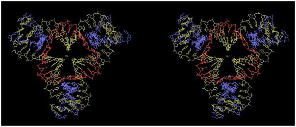
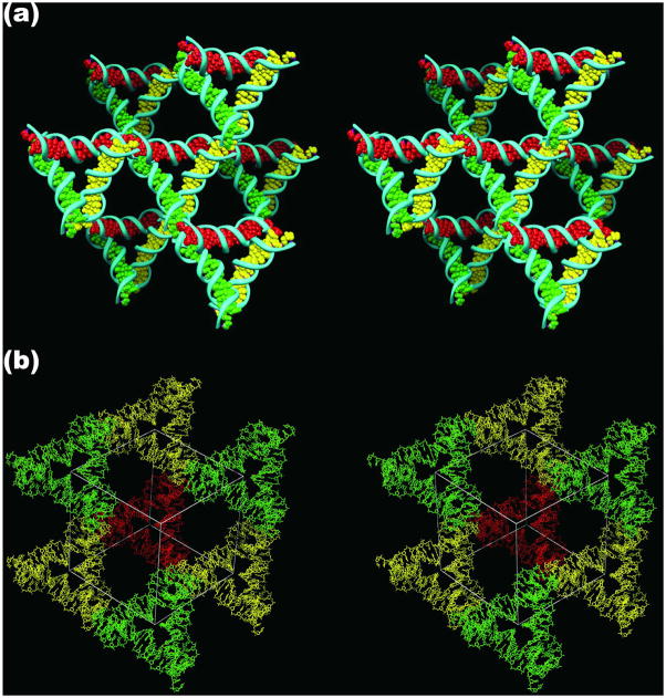
The first robust 3-space-spanning motif was the tensegrity triangle, first reported by Mao and his colleagues.32 This molecule is shown in stereographic projection in Figure 1. The molecule shown in Figure 1 is a rotationally 3-fold symmetrized species, because only three unique strands are used (see the color scheme), and the three sticky ends are identical. There is a nick in the middle of one of the helical domains, and it, too, is symmetrized in a three-fold fashion. Each of the three helical domains is two turns of DNA long. The molecule has been self-assembled into macroscopic rhombohedral crystals (~250 microns per edge) that diffract to 4 Å resolution.12 The crystal structure was solved by single anomalous diffractions methods, using an iodine derivative. Figure 2 illustrates the intermolecular interactions that result in the three dimensional crystal. Figure 2a shows one tensegrity triangle flanked by its six nearest neighbors in three different directions. The base pairs in the three different directions are indicated by different colors, red, green and yellow. It is readily apparent from this representation that the structure extends infinitely in all three directions. Another perspective on the crystal structure is shown in Figure 2b, which shows the rhombohedron flanked by eight of the tensegrity triangles. There is a cavity in the interior of the rhombohedron that has a volume of about 100 nm3.
Figure 1. A Stereoscopic Image of the Tensegrity Triangle.
The three unique strands are shown in individual colors. The blue strands are on the periphery of the triangle, the yellow strands form continuous helices and the red strand is a cyclic covalent strand containing a single nick distal to any crossover points.
Figure 2. The Lattice Formed by the Tensegrity Triangles.
(a) The Surroundings of an Individual Triangle. This stereoscopic simplified image distinguishes the three independent directions by the colors (red, green and yellow) of their base pairs. Thus, the central triangle is shown flanked by three other pairs of triangles in the three differently colored directions. (b) The Rhombohedral Cavity Formed by the Tensegrity Triangles. This stereoscopic projection shows seven of the eight tensegrity triangles that comprise the corners of the rhombohedron. The outline of the cavity is shown in white. The red triangle at the back connects through one edge each to the three yellow triangles that lie in a plane somewhat closer to the viewer. The yellow triangles are connected through two edges each to two different green triangles that are in a plane even nearer the viewer. A final triangle that would cap the structure has been omitted for clarity. This triangle would be directly above the red triangle, and would be even closer to the viewer than the green triangles.
The advantage of self-assembling a 3D motif into a crystal via sticky ends is that the same procedure can be used to produce numerous crystals. A variety of crystals have been self-assembled in the same way as the crystal that is shown in Figure 2.12 These include molecules that contain three or four turns per edge. The three-turn triangle crystals have cavities that contain around 350–400 nm3 and the four-turn triangle crystals have cavities whose volume is roughly a zeptoliter (1000 nm3). Unfortunately, the resolution of the crystals decreases as the edge-length increases: The three-turn triangles diffract to ~6.5 Å resolution, and the four-turn triangles diffract to ~10–11 Å resolution. Another advantage of self-assembling robust motifs with sticky ends in 3D was first shown in 2D.5,21,25 It is straightforward to choose the number of different species per crystallographic asymmetric unit. Recently, we have built crystals with two different triangles per asymmetric unit, and have demonstrated that we can control their colors by adding unique dyes covalently to the different triangles in the repeating unit (T. Wang, R. Sha, J.J. Birktoft, J. Zheng, C. Mao & NCS, in preparation).
DNA Origami
DNA origami has proved to be a revolutionary technique for the moderate-resolution (~6 nm) organization of DNA information into one, two or three dimensions. The method entails the use of a long scaffolding strand to which a series of smaller ‘staple’ strands or ‘helper’ strands are added. The staple strands are used to fold the scaffolding strand into a well-defined shape. The first example of a scaffolding strand in structural DNA nanotechnology was reported by Yan et al.,33 who used one to make a 1D ‘barcode array. This application of scaffolding was followed quickly by Shih et al.,18 who used a long strand of DNA with five short helper strands to build an octahedron held together by PX cohesion.34 However, neither of these two advances had the dramatic impact of Rothemund’s 2006 publication.28 He demonstrated that he was able to take single-stranded M13 viral DNA and get it to fold into a variety of shapes, including a smiley face (Figure 3a). One of the great advantages of this achievement is that it creates an addressable surface area roughly 100 nm square. This is about the area of 25 TX tiles connected 1–3, 6,21 constructed with minimal effort and with apparently little need for strict stoichiometry. One can use the hairpin component of the DX+J motif,2 developed for patterning 2D arrays,2,5 to generate patterns on DNA origami constructs. An example is seen in Figure 3b, which shows a map of the western hemisphere. DNA origami has become widely used since it was introduced, and has been employed for embedding nanomechanical devices,22 for making long 6-helix bundles35 to use as an aid to NMR structure determination,36 and for building 3D objects,37 including a box that can be locked and unlocked, with potential uses in therapeutic delivery.38 Most recently, an origami base has been used as the support for a nanomechanical assembly line23 and as a scaffold for the assembly of carbon nanotubes as a field effect transistor.39
Figure 3. Atomic Force Micrographs of DNA Origami Constructs.
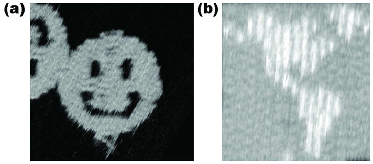
(a) A Smiley Face. The scaffold strand, bound to helper strands, zigzags back and forth from left to right, yielding the structure seen. (b) A Map of the Western Hemisphere. This image demonstrates dramatically the addressability of the DNA array. Each of the white pixels is made by a small DNA double helical domain roughly normal to the surface.
2D Algorithmic Assembly
Winfree first enunciated the goal of using DNA tiles to perform computation by self-assembly.40 The idea is that the tiles can be used individually as logic gates. Sticky ends on one helical domain of a DX tile, for example, can code for 0s or 1s that correspond to inputs, and the sticky ends on the other domain can act as output, again, either 0 or 1. One dimensional self-assembly of DX tiles representing exclusive-or (XOR) tiles had already been achieved in 2000,10 but 2D assembly had not yet been achieved. Algorithmic self-assembly is more difficult than conventional self-assembly: In conventional self-assembly, correct tiles are competing for a slot only with incorrect tiles. However, in algorithmic self-assembly, correct tiles are competing with half-correct tiles. An experimental solution to this problem during assembly was achieved for a very simple case that will be described below.22
During the past decade, two dimensional algorithmic self-assembly of Sierpinski triangles has been achieved. The Sierpinski triangle corresponds to Pascal’s triangle, mod 2: All the even numbers are replaced by 0 and all the odd numbers are replaced by 1. Consequently, it is a 2D version of the XOR operation. The first example of making a Sierpinski triangle was subject to a number of errors, but nevertheless the fractal pattern was observable.13 In the second example, an origami seed and a flanking set of tiles were used to ‘chaperone’ the growth of the structure, much as a biological chaperone controls the folding of a protein. A schematic and AFM image from reference 41 are shown in Figure 4. Counting has also been done with algorithmic assembly, although it has not been highly successful yet.42, 43
Figure 4. Seeded and Chaperoned Growth of Sierpinski Triangles.
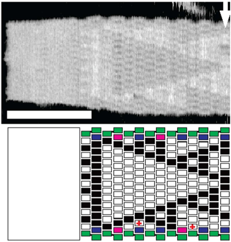
The upper panel shows an AFM image of a Sierpinski triangle that is seeded by a DNA origami on the left. The lower panel is an interpretation. The tiles that flank the rectangle on the top and the bottom provide extra control on the growth of the image. The scale bar is 100 nm, and the arrow indicates where analysis stopped following change in width of the sample.
The implications of algorithmic self-assembly for control of materials should not be underestimated. If it proves possible to build in 2D or 3D self-assembling tiles that can count successfully and that flank a growing crystal, it will be possible to build crystals to precise dimensions, because they will not grow past the appropriate flanking tiles. If successful, this approach will lead to revolutionary control of the structure of matter. Of course, it is much easier to analyze the results of self-assembly in 2D than in 3D: AFM enables the direct assessment of the placement of topographic markers indicating the presence of, say, 1s in a field of 0s; by contrast, 3D crystalline arrays are usually analyzed by X-ray crystallography, which only looks at the space-averaged structure of the crystalline electron density function.
DNA Devices, Walkers and 2D DNA Array Supports
A variety of DNA nanomechanical devices have been produced, but the most interesting ones are those that are sequence dependent, so that a number of them can be addressed individually in the same physical context. All of these devices are based on the Yurke et al.9 principle of toeholds that enable one to increase the number of base pairs formed at a given stage, so as to drive a reaction forward. The method that is used to change states is to add an 8-nucleotide ‘toehold’ to a controlling strand in the system. This toehold is designed to be unpaired when added to the device. It is removed by the addition of the complete complement to the strand containing the toehold. The complement binds to the toehold and removes the rest of the strand through branch migration. Virtually every sequence-specific device utilizes this toehold principle.
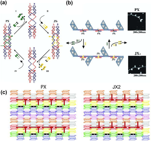
A nanomechanical device is termed ‘robust’ if it behaves like a macroscopic device, neither multimerizing nor dissociating when going through its machine cycle. The machine cycle of a robust sequence-dependent device controlled by ‘set’ strands44 is shown in Figure 5a. This device has two states, called PX and JX2, which differ from each other by a half-turn rotation between their tops and bottoms. Starting in the PX state at left, addition of the full complement to the green set strands (tailed in a biotin, represented by a black dot) removes the green strands, leaving a naked frame. Addition of the yellow set strands switches the device to the JX2 state. The cycle is completed when the complements of the yellow strands are added to strip them from the frame and the green set strands are added. Figure 5b shows in schematic that changing states can affect the structure of reporter trapezoids connected by the device. This Figure also shows AFM images of these state changes.
Figure 5. DNA-Based Nanomechanical Devices.
(a) The Machine Cycle of a PX-JX2 Device. Starting with the PX state on the left, the green set strands are removed by their complements (Process I) to leave an unstructured frame. The addition of the yellow set strands (process II) converts the frame to the JX2 state, in which the top and bottom domains are rotated a half turn relative to their arrangement in the PX conformation. Processes III and IV reverse this process to return to the PX structure. (b) AFM Demonstration of the Operation of the Device. A series of DNA trapezoids are connected by devices. In the PX state, the trapezoids are in a parallel arrangement, but when the system is converted to the JX2 state, they are in a zigzag arrangement. (c) Insertion of a Device Cassette into a 2D Array. The eight TX tiles that form the array are shown in differently colored outlined tiles. For clarity the cohesive ends are shown to be the same geometrical shape, although they all contain different sequences. The domain connecting the cassette to the lattice is not shown. The cassette and reporter helix are shown as red filled components; the black marker tile is labeled ‘M’ and is shown with a black filled rectangle representing the domain of the tile that protrudes from the rest of the array. Both the cassette and the marker tile are rotated about 103° from the other components of the array (three nucleotides rotation). The PX arrangement is shown at the left and the JX2 arrangement is on the right. Note that the reporter hairpin points towards the marker tile in the PX state, but points away from it in the JX2 state.
The notion of combining devices and lattices enables one not only to place atoms at desired locations in a fixed fashion, but to vary their positions over time in a programmed fashion. This goal has been achieved in 2D21,22 by developing a cassette with three components: One component is the PX-JX2 device, the second is a domain that attaches the cassette to a 2D array, and the third is a reporter arm whose orientation can be detected by AFM. This system is illustrated in Figure 5c, where the device has been incorporated into an eight-tile TX lattice. The PX state is shown on the left and the JX2 state is shown on the right. The reporter arm is seen to change its orientation relative to a marker tile (black) when the device state is switched.
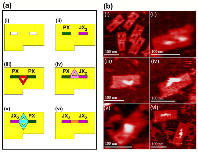
The combination of DNA devices and 2D DNA supports has been greatly simplified by DNA origami. In one application, two cassettes facing each other were incorporated into an origami. Each domain of the cassette had a sticky end, so that four configurations of sticky ends could be achieved.22,45 Thus, four different species could, in principle be captured by programming states of the devices. This system is shown both in schematic and in AFM images in Figure 6. An even more complex combination of DNA origami with a walker, nanoparticles and nanomechanical devices is a proximity-based nanoscale assembly line.23 Three device cassettes are inserted into a DNA origami. Three cargoes (a 5 nm particle, a 10 nm particle and two coupled 5 nm particles) are attached to arms that can be oriented towards or away from the center of the origami. Each can be programmed independently to be added to a walker that is passing by the different cassettes. Depending on the programming, any of eight products can be assembled. Figure 7 shows the assembly of the largest product, where all three cargoes are added to a triangular walker that walks on a track on the origami. AFM images showing only the cargoes and the origami are seen at right.
Figure 6. Schematics (a) and Atomic Force Micrographs (b) of the Origami Arrays and Capture Molecules.
Panel i of (a) illustrates the origami array containing slots for the cassettes and a notch to enable recognition of orientation; the slots and notches are visible in the AFM in (b). Panels ii show the cassettes in place; the color coding in (a) used throughout the schematics is green for the PX state and violet for the JX2 state; the presence of the cassettes is evident in the AFM image in (b). Panels iii illustrate the PX-PX state which captures a triangle pointing towards the notch in the schematic (a) and in the AFM image (b). Panels iv illustrate the PX-JX2 state (a), containing a triangle that points away from the notch, which is evident in the AFM image (b). Panels v illustrate the JX2- PX state which captures a diamond-shaped molecule (a); its shape is visible in the AFM image (b). Panels vi show the linear molecule captured by the JX2-JX2 state, both schematically (a) and in the AFM image (b).
Figure 7. The Steps in the Assembly Line Construction of a Triple Addition Product.
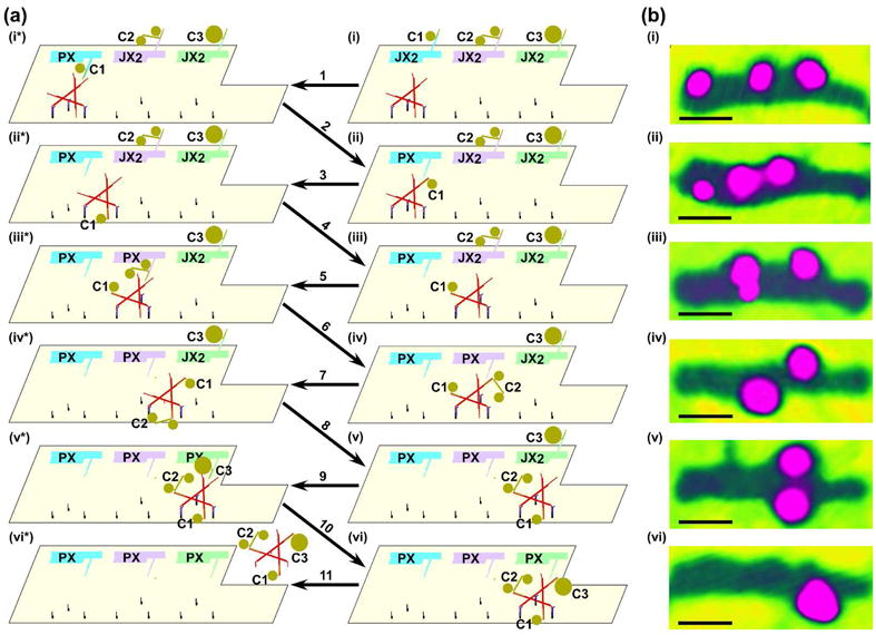
Schematics are shown in (a) and atomic force micrographs of the right column of (a) are shown in (b). AFM was performed by tapping in air; this mode of AFM results in only the nanoparticles and the origami being visible, and the individual nanoparticle components are not resolved from each other. Owing to the washing procedures between steps, the AFM images are not of the same individual assembly line. Panel i illustrates the origami array with cassettes and walker in the starting position. The cassettes are set to the default JX2 state, with the arms pointing away from the walker pathway. Different cargoes on the arms (5 nm Au on cassette 1, a linked 5 nm Au pair on cassette 2, and a 10 nm Au on cassette 3) are visible both schematically (a) and in the AFM (b). Step 1 shows cassette 1 switched from the JX2 state to the PX state, bringing cargo 1 close to the walker. Step 2 illustrates the addition of cargo 1 from cassette 1 to the walker by DNA branch migration; the movement of cargo 1 is evident in the AFM (ii). Step 3 shows the walker with cargo 1 walking the 1st half-step along the pathway; step 4 illustrates the walker with cargo 1 walking the 2nd half-step, positioning itself near cassette 2, which is visible both schematically and in the AFM (iii). Step 5 shows cassette 2 is switched from the JX2 state to the PX state, bringing cargo 2 close to the walker. Step 6 illustrates the addition of cargo 2 from cassette 2 to the walker by branch migration; the addition of cargo 2 is evident in the AFM (iv). Step 7 shows the walker with cargo 1 and cargo 2 walking the 3rd half-step along the pathway. Step 8 illustrates the walker with both cargo 1 and cargo 2 walking the 4th half-step to be close to cassette 3; the walking is clearly visible in the AFM (v). Step 9 shows cassette 3 switched from the JX2 state to the PX state, bringing cargo 3 close to the walker. Step 10 illustrates the addition of cargo 3 from cassette 3 to the walker by branch migration; the addition of cargo 3 is visible in the AFM (vi). Step 11 shows the walker with all three cargo components released from the origami. All scale bars are 50 nm.
Nanoparticle Organization
The use of DNA to organize nanoparticles began in the 1990’s.46,47 During the past decade, this work has been extended greatly. There are a large number of studies in which small motifs, such as DX molecules, have been used to organize nanoparticles into 1D arrangements, sometimes on a 2D surface, such as a plane48 or a cylinder.49 DNA origami has also been used for this purpose.50 Several studies have organized multiple particles, such as the checkerboard arrangement shown in Figure 8.51 More recently, DNA has been used to make deliberately chiral tetrahedra,52 with different particles on each vertex. DNA cohesion has been used to make nanoparticle crystals a few microns in dimension, which diffract X-rays.53,54
Figure 8. Organizing Gold Nanoparticles with a 2D Motif.
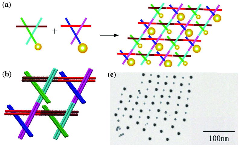
(a) Two different 3D-DX motifs, containing 5 nm or 10 nm particles on one end of a propagation direction yield a checkerboard nanoparticle array. (b) The two 3D-DX motifs in greater detail assembled to form a 2D array. (c) A TEM image showing a checkerboard array of gold nanoparticles.
Biological Replication of Nanostructures
When one hears of using DNA as a material, the possibility of using biological systems to replicate it immediately comes to mind. The key issue is topology: It is fairly simple to reproduce a linear single strand, but it is much more complex to reproduce the catenated or knotted structures of many DNA motifs. DNA origami26 is a compromise between natural replication of the M13 single-stranded form and the synthetic staple strands. The progenitor of origami noted above, Shih et al.’s octahedron,18 was also a compromise, although the bulk of the construct, a long single strand, was reproduced biologically. Yan and his colleagues have reported both the in vitro19 and in vivo20 replication of motifs topologically equivalent to a circle, such as a single-stranded branched junction and a paranemic crossover55 structure. It remains to be seen whether the biological machinery can deal with motifs that are topologically more complex, while remaining tight enough to be structurally interesting.
Looking Forward
There remain many problems confronting the field. We have only just achieved control in 3D, and the resolution of the crystals (4 Å) could certainly be improved. Indeed, it needs to be, if DNA crystals are to scaffold biological species for structural studies. We need to resolve whether the maximization of symmetry56 which leads to less purification, perhaps combined with biological production of strands, will improve crystals. Nanodevices are still very primitive, and the one assembly line now existing can be used only once. DNA is chemically incompatible with a lot of the species that one would like to scaffold with it. We are almost completely ignorant how analogs of DNA can be fit into the framework of structural DNA nanotechnology, even though those molecules are likely to be of great utility in overcoming chemical incompatibility, when applications are considered.
It is foolish to make predictions of developments in a field as large as structural DNA nanotechnology has become. Many of the most exciting achievements of the past decade, such as DNA origami, were not on the horizon a decade ago. I look forward to the coming decade with the hope that the promise of the field, control of the structure of matter in space and time to the greatest extent possible through programming the information in DNA, is likely to advance to an extent greater than the imagination of a single person can picture.
Acknowledgments
I thank all of my students, postdocs, collaborators and colleagues, who brought this field to its current state. I also thank Dr. Paul W.K. Rothemund for the use of Figure 3 and Dr. Satoshi Murata for the use of Figure 4. This work has been supported by grants GM-29544 from the National Institute of General Medical Sciences, CTS-0608889 and CCF-0726378 from the National Science Foundation, 48681-EL and W911NF-07-1-0439 from the Army Research Office, N000140910181 and N000140911118 from the Office of Naval Research and a grant from the W.M. Keck Foundation.
References
- 1.Seeman NC. J Theor Biol. 1982;99:237–247. doi: 10.1016/0022-5193(82)90002-9. [DOI] [PubMed] [Google Scholar]
- 2.Seeman NC. NanoLetters. 2001;1:22–26. [Google Scholar]
- 3.Chen J, Seeman NC. Nature. 1991;350:631–633. doi: 10.1038/350631a0. [DOI] [PubMed] [Google Scholar]
- 4.Zhang Y, Seeman NC. J Am Chem Soc. 1994;116:1661–1669. [Google Scholar]
- 5.Winfree E, Liu F, Wenzler LA, Seeman NC. Nature. 1998;394:539–544. doi: 10.1038/28998. [DOI] [PubMed] [Google Scholar]
- 6.LaBean TH, Yan H, Kopatsch J, Liu F, Winfree E, Reif JH, Seeman NC. J Am Chem Soc. 2000;122:1848–1860. [Google Scholar]
- 7.Mao C, Sun W, Seeman NC. J Am Chem Soc. 1999;121:5437–5443. [Google Scholar]
- 8.Mao C, Sun W, Shen Z, Seeman NC. Nature. 1999;397:144–146. doi: 10.1038/16437. [DOI] [PubMed] [Google Scholar]
- 9.Yurke B, Turberfield AJ, Mills AP, Jr, Simmel FC, Newmann JL. Nature. 2000;406:605–608. doi: 10.1038/35020524. [DOI] [PubMed] [Google Scholar]
- 10.Mao C, LaBean TH, Reif JH, Seeman NC. Nature. 2000;407:493–496. doi: 10.1038/35035038. [DOI] [PubMed] [Google Scholar]
- 11.Seeman NC. Ann Rev Biochem. 2010;79 doi: 10.1146/annurev-biochem-060308-102244. in press. [DOI] [PMC free article] [PubMed] [Google Scholar]
- 12.Zheng J, Birktoft JJ, Chen Y, Wang T, Sha R, Constantinou PE, Ginell SL, Mao C, Seeman NC. Nature. 2009;461:74–77. doi: 10.1038/nature08274. [DOI] [PMC free article] [PubMed] [Google Scholar]
- 13.Rothemund PWK, Papadakis N, Winfree E. PLoS Biol. 2004;2:2041–2052. doi: 10.1371/journal.pbio.0020424. [DOI] [PMC free article] [PubMed] [Google Scholar]
- 14.Sherman WB, Seeman NC. NanoLetters. 2004;4:1203–1207. [Google Scholar]
- 15.Shin JS, Pierce NA. J Am Chem Soc. 2004;126:10834–10835. doi: 10.1021/ja047543j. [DOI] [PubMed] [Google Scholar]
- 16.Green SJ, Bath J, Turberfield A. J Phys Rev Lett. 2008;101:238101. doi: 10.1103/PhysRevLett.101.238101. [DOI] [PubMed] [Google Scholar]
- 17.Omabegho T, Sha R, Seeman NC. Science. 2009;324:67–71. doi: 10.1126/science.1170336. [DOI] [PMC free article] [PubMed] [Google Scholar]
- 18.Shih WM, Quispe JD, Joyce GF. Nature. 2004;427:618–621. doi: 10.1038/nature02307. [DOI] [PubMed] [Google Scholar]
- 19.Lin C, Wang X, Liu Y, Seeman NC, Yan H. J Am Chem Soc. 2007;129:14475–14481. doi: 10.1021/ja0760980. [DOI] [PMC free article] [PubMed] [Google Scholar]
- 20.Lin C, Rinker S, Wang X, Liu Y, Seeman NC, Yan H. Proc Nat Acad Sci (USA) 2008;105:17626–17631. doi: 10.1073/pnas.0805416105. [DOI] [PMC free article] [PubMed] [Google Scholar]
- 21.Ding B, Seeman NC. Science. 2006;31:1583–1585. doi: 10.1126/science.1131372. [DOI] [PMC free article] [PubMed] [Google Scholar]
- 22.Gu H, Chao J, Xiao SJ, Seeman NC. Nature Nanotech. 2009;4:245–249. doi: 10.1038/nnano.2009.5. [DOI] [PMC free article] [PubMed] [Google Scholar]
- 23.Gu H, Chao J, Xiao SJ, Seeman NC. Nature. 2010 in press. [Google Scholar]
- 24.Pinto YY, Le JD, Seeman NC, Musier-Forsyth K, Taton TA, Kiehl RA. NanoLett. 2005;5:2399–2402. doi: 10.1021/nl0515495. [DOI] [PubMed] [Google Scholar]
- 25.Zheng J, Constantinou PE, Micheel C, Alivisatos AP, Kiehl RA, Seeman NC. NanoLett. 2006;6:1502–1504. doi: 10.1021/nl060994c. [DOI] [PMC free article] [PubMed] [Google Scholar]
- 26.Zhu L, Lukeman PS, Canary JW, Seeman NC. J Am Chem Soc. 2003;125:10178–10179. doi: 10.1021/ja035186r. [DOI] [PubMed] [Google Scholar]
- 27.Sharma J, Chhabra R, Cheng A, Brownell J, Liu Y, Yan H. Science. 2008;323:112–116. doi: 10.1126/science.1165831. [DOI] [PMC free article] [PubMed] [Google Scholar]
- 28.Rothemund PWK. Nature. 2006;440:297–302. doi: 10.1038/nature04586. [DOI] [PubMed] [Google Scholar]
- 29.Qiu H, Dewan JD, Seeman NC. J Mol Biol. 1997;267:881–898. doi: 10.1006/jmbi.1997.0918. [DOI] [PubMed] [Google Scholar]
- 30.Fu TJ, Seeman NC. Biochem. 1993;33:3311–3320. [Google Scholar]
- 31.Li X, Yang X, Qi J, Seeman NC. J Am Chem Soc. 1996;118:6131–6140. [Google Scholar]
- 32.Liu D, Wang W, Deng Z, Walulu R, Mao C. J Am Chem Soc. 2004;126:2324–2325. doi: 10.1021/ja031754r. [DOI] [PubMed] [Google Scholar]
- 33.Yan H, LaBean TH, Feng L, Reif JH. Proc Nat Acad Sci. 2003;100:8103–8108. doi: 10.1073/pnas.1032954100. [DOI] [PMC free article] [PubMed] [Google Scholar]
- 34.Zhang X, Yan H, Shen Z, Seeman NC. J Am Chem Soc. 2002;124:12940–12941. doi: 10.1021/ja026973b. [DOI] [PubMed] [Google Scholar]
- 35.Mathieu F, Liao S, Mao C, Kopatsch J, Wang T, Seeman NC. NanoLett. 2005;5:661–665. doi: 10.1021/nl050084f. [DOI] [PMC free article] [PubMed] [Google Scholar]
- 36.Douglas SM, Chou JJ, Shih WM. Proc Nat Acad Sci (USA) 2007;104:6644–6648. doi: 10.1073/pnas.0700930104. [DOI] [PMC free article] [PubMed] [Google Scholar]
- 37.Douglas SM, Dietz H, Liedl T, Högborg B, Graf F, Shih WM. Nature. 2009;459:414–418. doi: 10.1038/nature08016. [DOI] [PMC free article] [PubMed] [Google Scholar]
- 38.Andersen ES, Dong M, Nielsen MM, Jahn K, Subramani R, Mamdouh W, Golas MM, Sander B, Stark H, Oliviera CLP, Pedersen JS, Birkedal V, Besenbacher F, Gothelf KV, Kjems J. Nature. 2009;459:73–76. doi: 10.1038/nature07971. [DOI] [PubMed] [Google Scholar]
- 39.Maun HP, Han SP, Barish RD, Bookrath M, Goddard WA, Rothemund PWK, Winfree E. Nature Nanotech. 2010;5:61–66. doi: 10.1038/nnano.2009.311. [DOI] [PubMed] [Google Scholar]
- 40.Winfree E. In: DNA Based Computing. Lipton EJ, Baum EB, editors. Providence: Am. Math. Soc; 1996. pp. 199–219. [Google Scholar]
- 41.Fujibayashi K, Hariadi R, Park SH, Winfree E, Murata S. NanoLett. 2008;8:1791–1797. doi: 10.1021/nl0722830. [DOI] [PubMed] [Google Scholar]
- 42.Barish RD, Rothemund PWK, Winfree E. NanoLett. 2005;5:2586–2592. doi: 10.1021/nl052038l. [DOI] [PubMed] [Google Scholar]
- 43.Barish RD, Schulman R, Rothemund PWK, Winfree E. Proc Nat Acad Sci (USA) 2009;106:6054–6059. doi: 10.1073/pnas.0808736106. [DOI] [PMC free article] [PubMed] [Google Scholar]
- 44.Yan H, Zhang X, Shen Z, Seeman NC. Nature. 2002;415:62–65. doi: 10.1038/415062a. [DOI] [PubMed] [Google Scholar]
- 45.Carbone A, Seeman NC. Proc Nat Acad Sci (USA) 2002;99:12577–12582. doi: 10.1073/pnas.202418299. [DOI] [PMC free article] [PubMed] [Google Scholar]
- 46.Alivisatos AP, Johnson KP, Peng XG, Wilson TE, Loweth CJ, Bruchez MP, Schultz PG. Nature. 1996;382:609–611. doi: 10.1038/382609a0. [DOI] [PubMed] [Google Scholar]
- 47.Mirkin CA, Letsinger RL, Mucic RC, Storhoff JJ. Science. 1996;382:607–609. doi: 10.1038/382607a0. [DOI] [PubMed] [Google Scholar]
- 48.Pinto YY, Le JD, Seeman NC, Musier-Forsyth K, Taton TA, Kiehl RA. NanoLett. 2005;5:2399–2402. doi: 10.1021/nl0515495. [DOI] [PubMed] [Google Scholar]
- 49.Sharma J, Chhabra R, Cheng A, Brownell J, Liu Y, Yan H. Science. 2008;323:112–116. doi: 10.1126/science.1165831. [DOI] [PMC free article] [PubMed] [Google Scholar]
- 50.Ding B, Deng Z, Yan H, Cabrini S, Zuckerman RN, Bokor J. J Am Chem Soc. 2010;132:3248–3249. doi: 10.1021/ja9101198. [DOI] [PubMed] [Google Scholar]
- 51.Zheng J, Constantinou PE, Micheel C, Alivisatos AP, Kiehl RA, Seeman NC. NanoLett. 2006;6:1502–04. doi: 10.1021/nl060994c. [DOI] [PMC free article] [PubMed] [Google Scholar]
- 52.Mastroianni AJ, Claridge SA, Alivisatos AP. J Am Chem Soc. 2009;131:8455–8459. doi: 10.1021/ja808570g. [DOI] [PMC free article] [PubMed] [Google Scholar]
- 53.Nykypanchuk D, Maye MM, van der Lelie D, Gang O. Nature. 2008;451:549–552. doi: 10.1038/nature06560. [DOI] [PubMed] [Google Scholar]
- 54.Park SY, Lytton-Jean AKR, Lee B, Weigand S, Schatz GC, Mirkin CA. Nature. 2008;451:553–556. doi: 10.1038/nature06508. [DOI] [PubMed] [Google Scholar]
- 55.Shen Z, Yan H, Wang T, Seeman NC. J Am Chem Soc. 2004;126:1666–1674. doi: 10.1021/ja038381e. [DOI] [PMC free article] [PubMed] [Google Scholar]
- 56.Liu H, Chen Y, He Y, Ribbe AE, Mao C. Angew Chemie Int Ed. 2006;45:1942–1945. doi: 10.1002/anie.200504022. [DOI] [PubMed] [Google Scholar]


