Abstract
In the absence of applied forces, the transport of molecules and particulate reagents across laminar flowstreams in microfluidic devices is dominated by the diffusivities of the transported species. While the differential diffusional properties between smaller and larger diagnostic targets and reagents have been exploited for bioseparation and assay applications, there are limitations to methods that depend on these intrinsic size differences. Here a new strategy is described for exploiting the sharply reversible change in size and magnetophoretic mobility of “smart” magnetic nanoparticles (mNPs) to perform bioseparation and target isolation under continuous flow processing conditions. The isolated 5 nm mNPs do not exhibit significant magnetophoretic velocities, but do exhibit high magnetophoretic velocities when aggregated by the action of a pH-responsive polymer coating. A simple external magnet is used to magnetophorese the aggregated mNPs that have captured a diagnostic target from a lower pH laminar flowstream (pH 7.3) to a second higher pH flowstream (pH 8.4) that induces rapid mNP dis-aggregation. In this second disaggregated state and flowstream, the mNPs continue to flow past the magnet rather than being immobilized at the channel surface near the magnet. This stimuli-responsive reagent system has been shown to transfer 81% of a model protein target from an input flowstream to a second flowstream in a continuous flow H-filter device.
Introduction
The small dimensions of microfluidic channels have enabled the exploitation of interesting fluidic transport properties at low Reynolds numbers in laminar flow devices1-9. Flow can be kept laminar at reasonable flow rates due to the extremely small inertial forces that characterize flow in such structures. This allows the adjacent movement of layers of different fluids without transverse convective mixing. Because of the small lateral distances in such channels, diffusion can be a powerful tool for rapid separation of molecules and small particles according to their diffusion coefficients. One of the earliest microfluidic applications of the low Reynolds number flow devices was aimed at bioseparation needs associated with diagnostic assays. The H-filter and T-sensor devices exploited laminar flow conditions to perform continuous flow separations of molecular or cellular components10-18. The H-filter allows continuous extraction of analytes from particulate-laden fluids (e.g., blood, bacterial suspensions, saliva and environmental samples) without the need for a membrane filter or similar components.
An alternative general approach for diagnostic target purification utilizes functionalized particles with specific target binding activity. The challenge is to recover the dispersed particles for washing, concentration, and subsequent analysis steps. Magnetic particles offer opportunities for target purification via an integrated magnetic field19-26, although challenges due to their propensity for irreversible aggregation and low separation efficiency have been noted27,28. Compared to larger magnetic particles, nanoparticles have many potential advantages related to their diffusive and superparamagnetic properties29,30. However, magnetic nanoparticles (mNPs) also suffer from low magnetophoretic mobility31, limiting their utility for separations using low field-strength magnets32. We have previously reported a strategy utilizing smart polymer coated mNPs for maintaining the advantages of small nanoparticles during binding while introducing switchable transitions to larger, aggregated mNPs that exhibit excellent magnetophoretic mobilities33.
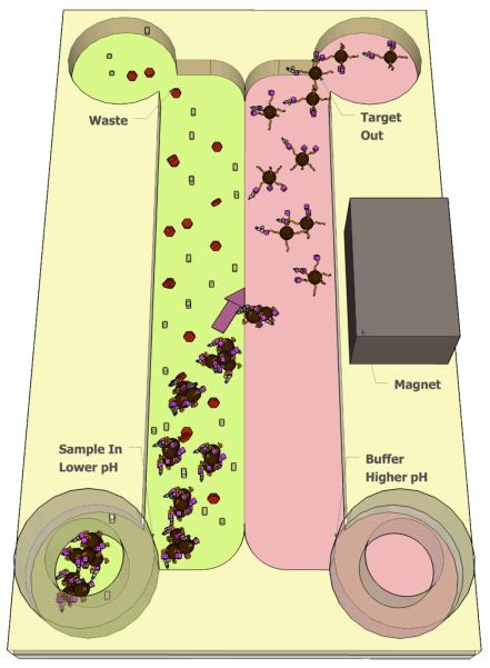
In this report we have combined for the first time laminar flow devices with smart mNPs whose magnetophoretic mobility can be reversibly switched by solution conditions. Where current applications with mNPs have relied on surface capture near the magnet, this system is designed to magnetically pull aggregated mNPs (and associated bound targets) from one flowstream laterally across the “laminar fluid interface” to another adjacent flowstream. The second flowstream is composed of a solution in which the nanoparticles disaggregate to isolated nanoparticles of low magnetophoretic mobility. The mNPs thus flow via the second laminar stream to the second fork in the H-filter output, rather than being captured at the magnet surface, and are separated from the starting first flowstream at the H-filter fork (Scheme 1). Solution pH is an attractive stimulus option for triggering the disaggregation of the mNPs because relatively simple cards can produce a steady-state pH gradient under continuous flow18, 34, and pH can be varied over useful ranges over relatively short distances. Here we demonstrate the use of these pH-sensitive mNPs in a simple, continuous flow microfluidic device to capture a model protein target (a fluorescently labeled streptavidin), to magnetophoretically extract the target protein from one stream to another, and to rapidly redissolve the mNPs for downstream collection and analysis.
Scheme 1.
Target analyte separation in a microfluidic channel facilitated by pH-responsive mNPs under isothermal conditions. The channel contains two flow streams. The left stream (green) is the sample that has been pre-incubated with mNPs. mNP aggregation is induced by using a lower pH buffer in this sample flowstream. The pH of the right stream (pink) is chosen to reverse mNP aggregation. A rare-earth magnet provides sufficient magnetic field to attract the aggregates laterally into the higher pH flowstream. The conjugate aggregates move out of the sample flowstream and in to the higher pH stream, where they return to a dispersed state, carrying the bound target analyte with them. Movement of other molecules across this interface is limited by diffusion due to the low Reynolds' number (laminar) fluid flow.
Experimental Section
Materials
N-Isopropylacrylamide (NIPAAm) (Aldrich, 97%) was recrystallized from benzene/hexane 3:2 (v:v) and dried under vacuum prior to use. tert-butyl methacylate (tBMA) (Aldrich, 98%), iron pentacarbonyl/Fe(CO)5 (Aldrich, 99.999%), 4,4′-Azobis(4-cyanovaleric acid) (Aldrich, 75+%), tetraethylene glycol dimethyl ether/tetraglyme (Aldrich, 99%), methanol (EMD, 99.8%), hexane (EMD, 89.2%), tetrahydrofuran/THF (EMD, 99.99+%), p-dioxane (EMD, 99%), biotin (Aldrich), HABA/avidin reagent (Aldrich), EZ-Link biotin-LC-PEO-amine (Pierce), and N,N′-dicyclohexylcarbodiimide (DCC; Pierce) were all used without any further purification.
Synhesis of poly (tert-butyl methacrylate-co-N-isopropylacrylamide)
Polymerization of P(tBMA-co-NIPAAm) was carried out according to a previously published protocol35 with minor modification. The target molecular weight was 11 kD with 10% tBMA. Briefly, 2 g of NIPAAm (monomer), 0.2 g of tBMA, 80.6 mg of 4-cyano-4-(dodecylsulfanylthiocarbonyl)sulfanyl pentanoic acid (trithiocarbonate-based CTA) synthesized according to a previously published protocol36, and 11.2 mg of 4,4′-azobis (4-cyano-valeric acid) (initiator) were mixed with 5 mL of methanol. After purging with nitrogen for 20 min, this solution was sealed and maintained at 70°C overnight. The solution was cooled down to room temperature and the methanol was removed by purging air. The polymer was dissolved with THF and precipitated in pentane for purification. The sample was dried overnight in vacuo.
Synthesis of pH-responsive mNPs (pH mNPs)
P(tBMA-co-NIPAAm) was dissolved in 25 mL tetraglyme (preheated to 100°C) at 3.06 mM and stirred for 30 minutes until the polymers dissolved completely. 100 μL of Fe(CO)5 (0.76 mmol) was added to the solution and the temperature was raised to 190°C after 5 min stirring. The solution was refluxed for 5 hours, and then cooled down to room temperature. The product was washed/precipitated in THF/n-hexane several times and dried overnight in vacuo.
Biotinylation of pH-responsive mNPs (b-pH mNPs)
pH mNPs were biotinylated via the carboxyl groups with carbodiimide chemistry. The carboxyl groups were activated with DCC in the presence of NHS. The ratio of the COOH group on the mNPs to NHS to DCC was 10:1:1. pH mNPs were suspended in dioxane. The calculated amount of NHS/DCC solution, which was prepared by premixing NHS and DCC in dioxane, was slowly added (over 15 min) to the particle suspension at 12°C. The desired amount of EZ-Link biotin-LC-PEO-amine was predissolved in dioxane and added to the particle solution, which was then stirred overnight. The mixed solution was stirred overnight and filtered to remove the urea. The particles were precipitated with n-hexane followed by centrifugation, vacuum-dried overnight then dialyzed against water (10 kD cutoff) for 72h and collected by lyophilization.
Conjugation of streptavidin (SA) to the b-pH mNPs
SA conjugates readily to the biotin groups. To prevent cross-linking, an excess amount of SA was used. b-pH mNPs and lyophilized SA were predissolved in 0.1 M phosphate-buffered saline (PBS) (pH 7.4, [NaCl] = 0.15 M) separately. The b-pH mNP suspension was slowly added to the streptavidin solution (over 30 min) at 4°C. The mixture was dialyzed against buffer using a dialysis membrane with an 100 kD MW cutoff for 72 hours at 4°C. Allowing the nanoparticle suspension come up to room temperature resulted in aggregates that were subsequently used in the microfluidic separation devices described below.
Characterization techniques
Polymer molecular weight
Molecular weights of copolymers were determined using a gel permeation chromatograph (Viscotek), using 0.01 mol/L LiBr DMF solution as eluent at a flow rate of 1 mL/min and at 60°C and narrow disperse poly(methyl methacrylate) as calibration standards.
1H NMR spectra of the copolymers were recorded on a Bruker AC 500, using methanol-d4 as the solvent. Compositions of P(tBMA-co-NIPAAm) copolymers were determined by comparing the peak areas of NIPAAm unit isopropyl C-H signal at 3.9 ppm and tBMA unit tert-butyl C-C3H9 at 1.4 ppm.
Lower Critical Solution Temperature (LCST) Measurement
The LCST was identified as the temperature at which 50% of the maximum absorbance at 550 nm was achieved. The concentration of polymer was 2 mg/mL in PBS. The data were collected using a UV-Vis spectrophotometer with a jacketed cuvette holder to control the temperature of the sample. A heating rate of 0.5°C/min was used, and absorbance values were measured every 0.5-1.0°C.
Transmission Electron Microscopy (TEM)
Nanocrystal size and morphology were investigated using a Phillips CM-100 Transmission Electron Microscope (100 KeV). Nanocrystals suspended in water, deposited onto a carbon stabilized Formvar-coated copper grid (400 mesh) and allowed to dry. The histogram was generated from manually measuring (UTHSCSA ImageTool version 3.00) particle size from the images.
Microfluidic Experiments
Microfluidic Channel Fabrication
Microchannels were fabricated from polylaminate Mylar substrates (Fraylock) with a nominal thickness of 0.010″ (254 μm), coated on both sides with a 0.001″ (254 μm) thick layer of adhesive (3M 501). Channels and inlet holes were cut into the substrates using a CO2 laser (Universal Laser Systems) operating at 10% speed, 80% power, and a PPI setting of 1000. After cutting, channels were adhered onto glass slides. A 0.1″ layer of PMMA was cut with larger inlet holes to serve as a holder for small rubber O-rings, which allowed tubing to interface with the device, and prevented leaks17.
Optical Microscopy and Fluid Control
Images were acquired using a monochrome CCD camera (Retiga-1300, Q Imaging, Burnaby, British Columbia) mounted to an inverted microscope (Eclipse TE2000U, Nikon USA). Positive displacement syringe pumps controlled by LabView software facilitated flow control.
Diffusivity and Magnetophoretic Velocity Simulations
The diffusivity (diffusion coefficient) (m2/s) of a given particle or aggregate size was estimated using the Stokes-Einstein relationship
where kB is the Boltzmann constant, T is the absolute temperature, η is the solution viscosity and r is the particle/aggregate size.
The magnetophoretic velocity, νM, as a function of particle size was estimated using a simple model31, 37,
where μm is the magnetophoretic mobility, ▽B is the magentic gradient, μ0 is the magnetic constant. ▽B was evaluated using FEMM (software). μm was caculated using
where M is the magnetic moment of the mNP.
Results and Discussion
The pH mNPs were synthesized in one step using a modified version of a previously published protocol33. (Scheme 2). Stimuli-responsive polymers have been synthesized that use ionization of carboxylate groups to achieve pH-responsiveness38. Carboxylate groups tend to interfere with micelle-templated γ-Fe2O3 nanoparticle growth39, however, and tert-butyl methacrylate (tBMA) was thus used as a protected form of methacrylic acid (MAA).
Scheme 2.
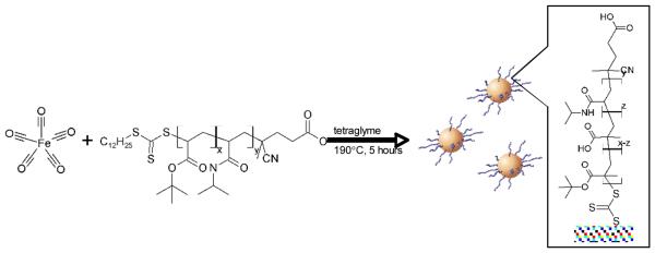
Synthesis of pH-responsive mNPs using polymeric micelles composed of amphiphilic pH-responsive polymer chains. The hydrophobic dodecyl group at one end of RAFT-synthesized P(tBMA-co-NIPAAm) chains formed micelles in tetraglyme, then loaded with Fe(CO)5 and heated at 190°C for 5 hours to synthesize the γ-Fe2O3 cores. Finally, the tert-butyl groups were partially cleaved and converted to carboxylates to generate pH-responsiveness.
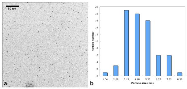
The P(tBMA-co-NIPAAm) copolymer chains were synthesized from a trithiocarbonate-based RAFT chain transfer agent (CTA) that contains a hydrophobic dodecyl group at one end. The polydispersity index of the polymer was ~1.1. These chains formed micelles in tetraglyme, driven by the association of the core-forming dodecyl groups. The micelles were loaded with Fe(CO)5 such that the core of the micelles served as dimensional confinements for the synthesis of the γ-Fe2O3 mNPs. TEM morphological characteriztion (Fig. 1) showed relatively normally distributed particle sizes averaging ~ 4.1 nm (± 1.6).
Fig. 1.
TEM image and the resulting size histograms of the pH-responsive mNPs: The mNPs were suspended in water and deposited onto a carbon stabilized Formvar-coated copper grids. The PNIPAAm is not stained, so only the γ-Fe2O3 (inorganic) portion of the mNPs is visualized. The inorganic core of the particles exhibits a spherical shape with a median size of 4.1 nm.
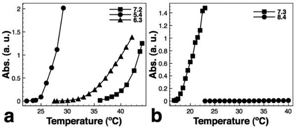
To characterize the tert-butyl group cleavage, P(tBMA-co-NIPAAm) alone was heated at 190°C in tetraglyme for 5 hours to simulate the mNP synthesis. Polymers were characterized using GPC, NMR and cloud point measurements before and after heating. The GPC chromatogram showed that the polymer molecular weight remains unchanged after heating. The isopropyl C-H of NIPAAm exhibits a distinct peak at ~ 3.9 ppm and the tert-butyl C-C3H9 of tBMA exhibits a distinct peak at ~ 1.4 ppm. The composition of P(tBMA-co-NIPAAm) was determined by 1H NMR peak area measurements. The NIPAAm:tBMA ratio is 0.87:0.13 indicating that the copolymer contains ~13% tBMA. The peak area ratio of the NIPAAm isopropyl C-H signal and tBMA tert-butyl C-C3H9 was 1:1.34 before heating and 1:0.794 after heating indicating that ~40% of tert-butyl groups were cleaved during the 5-hour heating. We therefore can conclude that ~40% of the tBMA were converted to MAA. Cloud point measurements (Fig. 2a) showed that the unheated polymer was insensitive to pH changes. The cloud point measurements for the polymer after heating was 27°C at pH 5.4, 39°C at pH 6.3 and 43°C at pH 7.2 because the heated polymer contains MAA that provides the pH-responsivness. The remaining hydrophobic tert-butyl groups facilitate the hydrophobic collapse of the polymer. The heated polymer therefore exhibited a sharper phase transition than the P(NIPAAm-co-MAA) with 10% MAA40.
Fig. 2.
Cloud point measurements for (a) free polymer and (b) biotinylated pH-responsive mNPs. (a) cloud point temperature increases with pH (27°C at pH 5.4, 39°C at pH 6.3 and 43°C at pH 7.2). (b) cloud point of the b-pH mNPs is 22°C at pH 7.3 and >40°C at pH 8.4.
As illustrated in Scheme 1, the general strategy is to mix the mNP conjugates containing capture moieties into the diagnostic sample as dispersed nanoparticles to allow the binding to target analytes. After the sample solution pH is adjusted (lower) to induce conjugate aggregation off the card, the solution is then introduced into the lab card into the laminar flowstream poised at this pH. As these aggregates flow through a magnetic field, they are magnetophoresed laterally across the laminar flow interface and into the adjacent higher pH stream, carrying the bound target analyte with them. Because the polymer coating is sharply pH-responsive, the aggregates redissolve rapidly and continue to flow in the receiving stream rather than being captured at the channel surface near the magnet. Movement of other molecules into the second flowstream is limited by diffusion due to the low Reynolds' number (laminar) fluid flow.
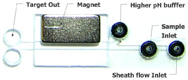
The increased lateral transport of the pH-responsive mNP aggregates in a magnetic field can be demonstrated using an H-shaped microfluidic channel (Fig. 3). The device contains three inlets and two outlets. Upstream are two fluidic inlets, one accomodating the lower pH solution and mNP aggregates, and the other introducing the higher pH buffer. A third inlet was used to establish a “sheath” flow of lower pH buffer under the sample inlet. This was necessary to prevent the aggregated particles from clumping and aggregating under the sample inlet port41. After the mNP aggregates flow through the channel, samples are collected from the different flowstream outlets at the H-filter fork to determine the mNP concentration in each outlet. The lab card experiments were monitored using fluorescent microscopy.
Fig. 3.
A microfluidic device for rapid separation and dis-aggregation of pH-responsive mNP aggregates. The device contains three inlets and two outlets. A buffer solution (sheath flow) is pumped into the rightmost inlet so that the particle suspension is deflected into the main channel prior to contacting the bottom surface, preventing gross particle aggregation and blockage under the sample inlet port. The higher pH buffer provides the stimulus for particle dis-aggregation once they are magnetophoretically transported across the pH gradient.
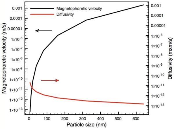
The diffusivity (m2/s) and magnetophoretic velocities (m/s) (Fig. 4) as a function of mNP aggregate size were estimated to validate the underlying transport properties that are manipulated in this system. The Stokes-Einstein relationship was used to estimate the particle diffusivity and a previously described model31,37 was used to estimate the magnetophoretic mobility of the magnetic particles. Diffusivity and magnetophoretic velocity were calculated as a function of particle/aggregate size. The magnetic field gradient generated by a neodymium-iron-boron magnet (maximum energy project as 32MGOe) was estimated using FEMM (software). The diffusivity of individual mNPs (~ 5 nm) is estimated to be 4.4 × 10⁻¹¹ m2/s and decreases as the particle size becomes larger. In contrast, the magnetophoretic velocity of individual mNPs is estimated to be 6.2 × 10⁻¹⁴ m/s but increases significantly as the particle size becomes larger. The magnetophoretic velocity of the 500 nm aggregates can be as high as 0.0062 m/s which is 10 orders of magnitude higher than the individual mNPs. The actual aggregates are heterogeneous in size but off-card DLS measurements demonstrate that the pre-aggregated mNP sizes are much greater than 1 μm. We therefore can conclude the magnetic separation is much more effective when the mNPs are aggregated, but sharply falls off as they redissolve to 5 nm isolated particles in the higher pH stream.
Fig. 4.
Calculation of diffusivity and magnetophoretic velocity as a function of particle size. The diffusivity of individual mNPs (~ 5 nm) was estimated to be 4.4 × 10⁻¹¹ m2/s and decreases with increasing particle size. In contrast, the magnetophoretic velocity of individual mNPs was estimated to be 6.2 × 10⁻¹⁴ m/s and increases significantly with particle size. The magnetophoretic velocity of the 500 nm aggregates can be as high as 0.0062 m/s which is 10 orders of magnitude higher than the individual mNPs.
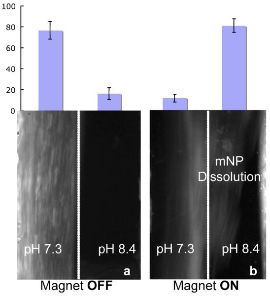
A model target analyte isolation was demonstrated using the lab card with biotinylated mNPs complexed to fluorescently-labeled streptavidin. The experiments were carried at room temperature (~23°C). The solution pH was adjusted to induce mNP aggregation off the card and then this sample was injected into pH 7.3 inlet. The flow rate for both inlets are ~9 μL/min. Fig. 5a shows the result when no magnetic field was applied. The SA-mNP conjugates stay aggregated in the pH 7.3 flowstream and only diffuse at low levels into the pH 8.4 flowstream because of the minimal lateral diffusion of these larger aggregates. When the magnetic field is applied (Fig. 5b), the large aggregates display strongly enhanced magnetophoretic mobility and the SA-mNPs are moved laterally across to the pH 8.4 buffer stream. A fluorescence microscope was used to assess the on-card mNP disaggregation. Initially, the aggregates are seen as punctate spots on the fluorescent images. When the aggregates move laterally across to the pH 8.4 buffer stream they rapidly disaggregate and the spots disappear as the fluorescent signal becomes uniform throughout the solution. The optical resolution is not sufficient to determine the size of the mNPs below ca. 5 μm, and therefore DLS measurements were conducted off-card to characterize the disaggregation process further. The mNPs were pre-aggregated in a lower pH buffer, and then DLS measurements were initiated after transfer into a cuvette containing the higher pH buffer for the mNP disaggregation. Each DLS measurement takes 30 seconds. The particle size after 30 seconds, 5 minutes and 10 minutes were 16.2, 13.7 and 16.7 nm, respectively, indicating the dissagregation occurred faster than the time resolution of the DLS experiment. Because of the flow conditions, the on-card mNP disaggreation is expected to be even more rapid.
Fig. 5.
Fluorescent microscopy results showing continuous stream purification of streptavidin-mNP conjugates. The magnet is located adjacent to the higher pH flowstream. The channel contains two fluidic streams flowing bottom to top. (a) No magnetic field. The conjugate aggregates largely remain in the left-hand stream and ca. 80% of the conjugates were isolated from the low pH outlet. (b) When the magnetic field is applied, the conjugate aggregates magnetophorese laterally across to the higher pH flowstream where they redissolve. When the magnetic field is applied, most conjugates were moved into the high pH stream and ca. 80% of the conjugates were collected from the right outlet.
When no magnetic field was applied (Fig. 5a), 77% of the injected SA-mNPs was measured in the pH 7.3 outlet and 16% of streptavidin exited the channel from the pH 8.4 outlet. When a magnetic field was applied (Fig. 5b), 81% of streptavidin exits the channel from the pH 8.4 outlet and only 12% from the pH 7.3 outlet. We therefore can conclude the bound streptavidin target can be efficiently separated under continuous flow conditions using the new pH-responsive mNP reagents.
Conclusions
A simple H-filter microfluidic system was used to demonstrate efficient continuous flow target separation across a laminar interface using pH-responsive mNPs. At room temperature the smart mNPs are soluble in pH 8.4 buffer and aggregate when the buffer pH becomes 7.3. To demonstrate continuous flow protein target isolation, fluorescently-labeled streptavidin was complexed to biotinylated, pH-responsive mNPs and introduced into the H-filter in the aggregated state at pH 7.3. Because of the laminar flow profile of the H-filter, the μm size conjugate aggregates largely stay in this lower pH flowstream and few cross the interface without an applied magnetic field. A simulation of diffusive and magnetophoretic velocities as a function of mNP aggregate size shows the magnetic separation is sharply more effective when the mNPs are aggregated (>50 nm), but sharply falls off as they redissolve to isolated particles (~5 nm) in the higher pH stream. When the magnet is turned on, however, the aggregated streptavidin-mNPs are magnetophoresed laterally into the higher pH flowstream where they rapidly redissolve. Approximately 80% of the target streptavidin is captured in the higher pH fork of the H-filter on the microfluidic lab card. This new pH-responsive mNP-microfluidic system thus represents a new approach to continuous stream diagnostic target purification and processing on point-of-care labcards.
Supplementary Material
Acknowledgement
The authors would like to express their gratitude to the NIH Grants EB000252 and NIDCR, grant number 5U01 DE014971.
Footnotes
Electronic Supplementary Information (ESI) available: [details of any supplementary information available should be included here].
Footnotes should appear here. These might include comments relevant to but not central to the matter under discussion, limited experimental and spectral data, and crystallographic data.
Notes and references
- 1.Sia SK, Whitesides GM. Electrophoresis. 2003;24:3563–3576. doi: 10.1002/elps.200305584. [DOI] [PubMed] [Google Scholar]
- 2.Liu YJ, Rauch CB, Stevens RL, Lenigk R, Yang JN, Rhine DB, Grodzinski P. Analytical Chemistry. 2002;74:3063–3070. doi: 10.1021/ac020094q. [DOI] [PubMed] [Google Scholar]
- 3.Tudos AJ, Besselink GAJ, Schasfoort RBM. Lab on a Chip. 2001;1:83–95. doi: 10.1039/b106958f. [DOI] [PubMed] [Google Scholar]
- 4.Srinivasan V, Pamula VK, Fair RB. Lab on a Chip. 2004;4:310–315. doi: 10.1039/b403341h. [DOI] [PubMed] [Google Scholar]
- 5.Ahn CH, Choi JW, Beaucage G, Nevin JH, Lee JB, Puntambekar A, Lee JY. Proceedings of the Ieee. 2004;92:154–173. [Google Scholar]
- 6.Doherty EAS, Meagher RJ, Albarghouthi MN, Barron AE. Electrophoresis. 2003;24:34–54. doi: 10.1002/elps.200390029. [DOI] [PubMed] [Google Scholar]
- 7.Khandurina J, Guttman A. Journal of Chromatography A. 2002;943:159–183. doi: 10.1016/s0021-9673(01)01451-0. [DOI] [PubMed] [Google Scholar]
- 8.Lee GB, Chen SH, Huang GR, Sung WC, Lin YH. Sensors and Actuators B-Chemical. 2001;75:142–148. [Google Scholar]
- 9.Yang J, Huang Y, Wang XB, Becker FF, Gascoyne PRC. Analytical Chemistry. 1999;71:911–918. doi: 10.1021/ac981250p. [DOI] [PubMed] [Google Scholar]
- 10.Abe K, Suzuki K, Citterio D. Anal. Chem. 2008 [Google Scholar]
- 11.Helton KL, Yager P. Lab on a Chip. 2007;7:1581–1588. doi: 10.1039/b709585f. [DOI] [PubMed] [Google Scholar]
- 12.Jandik P, Weigl BH, Kessler N, Cheng J, Morris CJ, Schulte T, Avdalovic N. Journal of Chromatography A. 2002;954:33–40. doi: 10.1016/s0021-9673(02)00160-7. [DOI] [PubMed] [Google Scholar]
- 13.Munson MS, Cabrera CR, Yager P. Electrophoresis. 2002;23:2642–2652. doi: 10.1002/1522-2683(200208)23:16<2642::AID-ELPS2642>3.0.CO;2-P. [DOI] [PubMed] [Google Scholar]
- 14.Erickson D, Li DQ. Analytica Chimica Acta. 2004;507:11–26. [Google Scholar]
- 15.Hatch A, Kamholz AE, Hawkins KR, Munson MS, Schilling EA, Weigl BH, Yager P. Nature Biotechnology. 2001;19:461–465. doi: 10.1038/88135. [DOI] [PubMed] [Google Scholar]
- 16.Holden MA, Kumar S, Castellana ET, Beskok A, Cremer PS. Sensors and Actuators B-Chemical. 2003;92:199–207. [Google Scholar]
- 17.Nelson K, Foley J, Yager P. ANALYTICAL CHEMISTRY. 2007;79:3542–3548. doi: 10.1021/ac062349w. [DOI] [PMC free article] [PubMed] [Google Scholar]
- 18.Cabrera CR, Finlayson B, Yager P. Analytical Chemistry. 2001;73:658–666. doi: 10.1021/ac000495a. [DOI] [PubMed] [Google Scholar]
- 19.Furdui VI, Harrison DJ. Lab on a Chip. 2004;4:614–618. doi: 10.1039/b409366f. [DOI] [PubMed] [Google Scholar]
- 20.Gijs MAM. Microfluidics and Nanofluidics. 2004;1:22–40. [Google Scholar]
- 21.Pamme N, Manz A. Analytical Chemistry. 2004;76:7250–7256. doi: 10.1021/ac049183o. [DOI] [PubMed] [Google Scholar]
- 22.Pamme N, Wilhelm C. Lab on a Chip. 2006;6:974–980. doi: 10.1039/b604542a. [DOI] [PubMed] [Google Scholar]
- 23.Pamme N. Lab on a Chip. 2006;6:24–38. doi: 10.1039/b513005k. [DOI] [PubMed] [Google Scholar]
- 24.Chapman PA, Wright DJ, Siddons CA. Journal of Medical Microbiology. 1994;40:424–427. doi: 10.1099/00222615-40-6-424. [DOI] [PubMed] [Google Scholar]
- 25.Tong XD, Xue B, Sun Y. Biotechnology Progress. 2001;17:134–139. doi: 10.1021/bp000134g. [DOI] [PubMed] [Google Scholar]
- 26.Kim KS, Park JK. Lab on a Chip. 2005;5:657–664. doi: 10.1039/b502225h. [DOI] [PubMed] [Google Scholar]
- 27.Molday RS, Molday LL. FEBS Letters. 1984;170:232–238. doi: 10.1016/0014-5793(84)81319-8. [DOI] [PubMed] [Google Scholar]
- 28.Yavuz CT, Mayo JT, Yu WW, Prakash A, Falkner JC, Yean S, Cong LL, Shipley HJ, Kan A, Tomson M, Natelson D, Colvin VL. Science. 2006;314:964–967. doi: 10.1126/science.1131475. [DOI] [PubMed] [Google Scholar]
- 29.LesliePelecky DL, Rieke RD. Chemistry of Materials. 1996;8:1770–1783. [Google Scholar]
- 30.Niemeyer CM. Angewandte Chemie-International Edition. 2001;40:4128–4158. doi: 10.1002/1521-3773(20011119)40:22<4128::AID-ANIE4128>3.0.CO;2-S. [DOI] [PubMed] [Google Scholar]
- 31.Chalmers JJ, Zhao Y, Nakamura M, Melnik K, Lasky L, Moore L, Zborowski M. Journal of Magnetism and Magnetic Materials. 1999;194:231–241. [Google Scholar]
- 32.Moeser GD, Roach KA, Green WH, Hatton TA, Laibinis PE. Aiche Journal. 2004;50:2835–2848. [Google Scholar]
- 33.Lai JJ, Hoffman JM, Ebara M, Hoffman AS, Estournes C, Wattiaux A, Stayton PS. Langmuir. 2007;23:7385–7391. doi: 10.1021/la062527g. [DOI] [PubMed] [Google Scholar]
- 34.Cui HC, Horiuchi K, Dutta P, Ivory CF. Analytical Chemistry. 2005;77:1303–1309. doi: 10.1021/ac048915+. [DOI] [PubMed] [Google Scholar]
- 35.Convertine AJ, Ayres N, Scales CW, Lowe AB, McCormick CL. Biomacromolecules. 2004;5:1177–1180. doi: 10.1021/bm049825h. [DOI] [PubMed] [Google Scholar]
- 36.Moad G, Chong YK, Postma A, Rizzardo E, Thang SH. Polymer. 2005;46:8458–8468. [Google Scholar]
- 37.Hütten A, Sudfeld D, Ennen I, Reiss G, Wojczykowski K, Jutzi P. Journal of Magnetism and Magnetic Materials. 2005;293:93–101. [Google Scholar]
- 38.Chen GH, Hoffman AS. Nature. 1995;373:49–52. doi: 10.1038/373049a0. [DOI] [PubMed] [Google Scholar]
- 39.Hyeon T. Chemical Communications. 2003:927–934. doi: 10.1039/b207789b. [DOI] [PubMed] [Google Scholar]
- 40.Yin X, Hoffman AS, Stayton PS. Biomacromolecules. 2006;7:1381–1385. doi: 10.1021/bm0507812. [DOI] [PubMed] [Google Scholar]
- 41.Munson MS, Hasenbank MS, Fu E, Yager P. Lab on a Chip. 2004;4:438–445. doi: 10.1039/b407765b. [DOI] [PubMed] [Google Scholar]
Associated Data
This section collects any data citations, data availability statements, or supplementary materials included in this article.


