Abstract
The centre of rotation of the hip can be displaced in hip dysplasia and revision arthroplasty. This study examined the effect of artificial femoral head load after acetabular component displacement in total hip arthroplasty. Sixteen total hip arthroplasty models of human cadaver specimens were reconstructed, and under different acetabular component position, the load around the femoral head was evaluated by strain gages. The results showed that the load was higher in the same specimens when the cup was moved 2 mm inward or upward, especially after the cup was moved more than 6 mm, and the load had an increasing effect in the inward group. In the upward group, an increasing effect happened at 8 mm upward displacement, but the stress value decreased from 4 mm to 6 mm upward displacement. In the same moving distance, the stress of inward displacement is obviously higher than upward displacement. Altogether, the results suggested that for both inward displacement and upward displacement of the acetabular cup, the load around the femoral head increased gradually, while the distance of the inward displacement and the superior displacement was increased. The greater the displacement, the bigger the loading contact stress. The upward displacement caused less stress change on the femoral head. The stress of the 6 mm upward position was lower than nearby positions; perhaps this site represented a stress buffering zone.
Introduction
After total hip arthroplasty, the implantation of prosthetic components radically alters the pathway of load transfer across the hip joint, consequently changing the original pattern of load in the hip joint. Due to stress shielding, the periprosthetic bone undergoes structural remodelling and/or bone absorption in the long-term. Additionally, because of cyclic stress developing at prosthetic components, they are subject to wear and fatigue. All these factors lead to adverse effects in the prostheses on long-term stability, and result in prostheses loosening in the late stage. Among all the causes for the alteration of stress distribution, the position and orientation of the acetabular cup plays an important role in addition to the design and material properties of the prostheses and the surgical technique.
Several studies now show that cup inclination is an important factor in wear, and cup inclination should be 45° or less because inclination greater than that is directly related to accelerated wear; others have suggested that the hip centre of rotation (COR) must be closely re-established to reduce wear [1–4]. However, there is no normal anatomical structure and/or the bone stock is poor in acetabular dysplasia and revision arthroplasty. It is not so difficult to achieve stable fixation of the cup in a position that provides hip stability and correct inclination using bone graft; whereas it is difficult to put the cup in the anatomical position so that the hip centre of rotation can be displaced, superiorly and/or medially to permit cup inclination below 45° with correct cup coverage [5–8]. However, these displacements would still cause accelerated wear [3, 9].
Therefore, the effect of the load on the artificial femoral head after total hip arthroplasty is important to achieve a better position in the displacement, especially in the inward an/or upward displacement which are the two most frequent occurrences in the surgery. Few studies have analysed this issue.
We conducted this study to determine the effect of load on the artificial femoral head after total hip replacement. Cadaveric pelvic specimens were used under different acetabular component positions to evaluate contact pressure between the artificial femoral head and acetabulum with strain gages.
Materials and methods
Through the Medical Ethics Committee of Sun Yat-sen University, 12 female cadavers were offered by the Department of Anatomy of Sun Yat-sen University, of which eight were selected because they were within a 5% of variation in pelvic bone size. Following the procedure of total hip arthroplasty of Zimmer M/L Taper Hip Prosthesis from Zimmer Inc. (Warsaw, IN, USA), these 16 artificial acetabular models of the human cadaver specimens were reconstructed for different acetabular component positions: two acetabular prosthesis were in anatomical position, seven acetabular prosthesis had an inward displacement ranging from 2 mm to 14 mm with 2-mm increments, and seven acetabular prosthesis had an upward displacement ranging from 2 mm to 14 mm with 2-mm increments. Briefly, the cadaver specimens were dissected of all soft tissue around the hip joint and the hip COR in different positions were located by graduated pins with inclination of 45°. Then 48-mm acetabular components were placed in different positions, also with inclination of 45°. The COR calculation in the cadaver was the same as the 3D biomechanical model [10, 11]: two strings were selected in the acetabular rim at random and the vertical intersection of the strings was the COR. Further, the exact COR calculation for every specimen was as follows: for inward or upward of 0 mm, the socket was just made to be a smooth, perfectly rounded surface to accept the size 48-mm acetabular component by the reamer, then the anatomical COR was calculated; for inward or upward of 2 mm, the acetabulum was treated to be the 0-mm position and the anatomical COR was calculated, then the 2-mm displacement of the COR was exactly located by a graduated pin. After the reconstruction of the 2-mm displacement acetubulum, the new COR was compared with the 0-mm displacement position. The procedure for the other positions was the same. Because one displacement could not be compared with the 0-mm displacement after the other acetabulum was reconstructed in the same cadaver, it was compared with the 2-mm less displacement in the same cadaver. For example, the 4-mm displacement could be compared with the 0-mm displacement before the other acetubulum was reconstructed in the same cadaver, but after the other acetubulum was reconstructed in the 6-mm displacement, the COR of the 6-mm displacement would be compared with the 4-mm displacement.
According to the anatomical acetabular positions, the pelvic specimens were divided into the inward displacement group and the upward displacement group. The inward displacement group contained one anatomical position (inward 0 mm) and seven inward positions (including inward 2 mm, 4 mm, 6 mm, 8 mm, 10 mm, 12 mm, and 14 mm, but 14 mm was not undertaken for large bone loss). The upward displacement group contained one anatomical position (upward 0 mm) and seven upward positions (including upward 2 mm, 4 mm, 6 mm, 8 mm, 10 mm, 12 mm, and 14 mm).
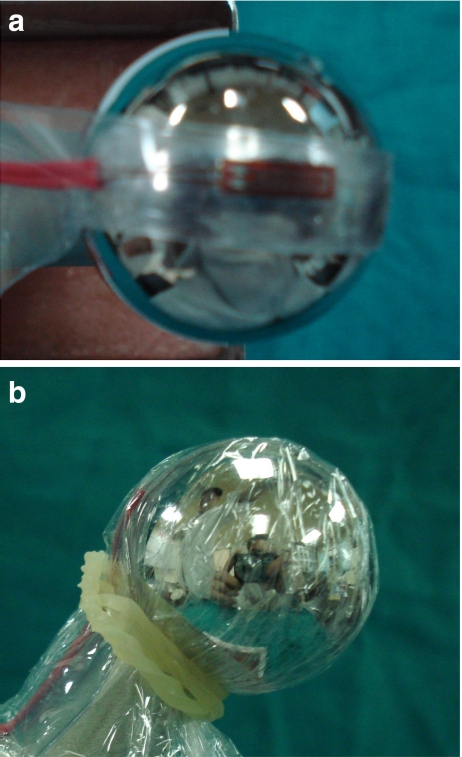
The superior and medial part of a size 28-mm artificial femoral head was cleaned and marked for strain gauges biaxially as recommended by Kyowa (KFG-5-120-C1-11L3M2R; Tokyo, Japan) (Fig. 1a). The dimensions of the strain gauges were 5 mm × 15 mm and the thickness was 33–38 μm. The shape of the strain gauges (sensitivity coefficient: 2.08 ± 1.0%) was adjusted with dimensions based on the curve of the femoral head. The strain gauges were glued on the marked central position in the superior and medial part of the femoral head using one drop of rapid cure adhesive (cyanoacrylate adhesive CC-33A, Kyowa). The strain gauge covered 34% of the half sphere in the mediolateral direction of the femoral head. An accessory film of polyethylene resin from Kyowa was used to cover the strain gages. A latex condom was placed over the strain gages (Fig. 1b) and the adhesive was allowed to completely harden for 60 minutes.
Fig. 1.
The sensor (5 mm × 15 mm) mounted on the superior and medial area of size 28-mm femoral head. a Strain gauges mounted. b Mounted sensor covered with latex condom
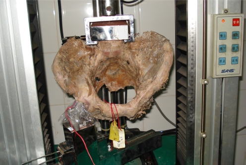
The sacrum of the pelvis and the artificial femur were embedded in a specimen holder with denture acrylic resin from Shanghai Medical Instruments (Shanghai, China) and placed in the SANS CMT 6104 material testing machine from MTS Co. (Shengzhen, China) (Fig. 2). The artificial femur was embedded in a specimen holder with denture acrylic resin and fixed with two pins. Specimens were oriented as follows: in the lateral view, anterior superior iliac spine and symphysis pubis vertically aligned, femoral prosthesis vertical; and in the anterior view, pelvis level horizontally, femoral prosthesis in 15° of adduction relative to the pelvis [12].
Fig. 2.
Pelvic specimen and femur prosthesis placement
After aligning the loading axis of the testing machine and the measuring points, the strain gauges were connected to the Kyowa PCD-300A strain data analysis system (Tokyo, Japan). Then, a hydraulic load at a rate of 4 mm/min was applied on the preload of 100 N up to 1000 N. To ensure stable performance of the strain gauges and to avoid onset of the null-shift phenomenon, we adjusted the strain data analysis system, including standardisation, zero setting, measurement, attenuation, etc. before real-time measurements. Moreover, the attenuation value was set to ten, with uniform sensitivity coefficients of the instrument and resistance strain gauge. Each experiment was repeated at least twice and results were averaged.
According to Hooke′s law, the relationship of stress and strain was expressed by the formula (stress = −E × strain, where E is the elasticity coefficient), so stress on each position is proportional to its strain, and compression or stretch of the strain gauge was expressed by the negative or positive symbol of the strain value. The analysis of variance between the two groups was done using F-test and Student′s t-test.
Results
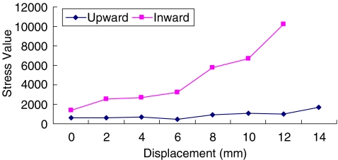
In the inward displacement of the acetabular group, the load around the artificial femoral head was higher, and had an increasing effect when the ingression was moved 2 mm more, especially after the inward distance was moved more than 6 mm (Fig. 3). In the inward 8 mm position, the stress on the femoral head was four times higher than the anatomical position.
Fig. 3.
Stress trend of the artificial femoral head under different displacements of the acetabulum
A similar trend was found in the upward group, and an increasing effect occurred at 8-mm upward displacement (Fig. 3). However, the stress of the 6-mm upward position was lower than nearby positions.
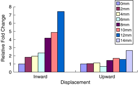
Comparison of the load around the artificial femoral head from the upward and inward groups (Figs. 3 and 4) showed that the stress of inward displacement is higher than upward displacement over the same distance. The upward displacement also caused less serious stress change (p < 0.002 in F-test, p < 0.02 in t-test).
Fig. 4.
The relative fold change comparison of stress on the artificial femoral head between upward displacement and inward displacement of the acetabulum (p < 0.002 in F-test, p < 0.02 in t-test)
Discussion
After total hip arthroplasty, the major mechanical problem is the change of the load on the artificial components and the femur, which influence the long-term results of artificial joints. To avoid this problem, proper placement of the acetabular centre of rotation in the operation is essential. There has been no clear conclusion about which acetabular COR is better until now, especially for patients suffering acetabular dysplasia, and after revision arthroplasty, in which there is no normal anatomical structure and bone mass is poor. In these patients, it is hard to place the COR in the anatomical position. Some studies showed that even if the prostheses is placed in the anatomical centre in an abnormal anatomical acetabulum, the compressive stress around the femoral head was still not within the normal range [10, 13]. Here, we identified the effect of biomechanical change on different acetabular centres, through creating 16 total hip arthroplasty models of the human cadaver specimens in upward or inward displacements.
Since Charnley et al. began studying acetabular displacement in the clinic for reduction of local compressive stress in 1970 [14], this research has continued. According to radiological case analysis, several studies showed that the acetabular centre inward or inferior displacement was better in terms of stress change [11, 15, 16]. However, some other studies reported better results of upward or upward with inward displacement of the acetabular centre using digital model analysis and clinical follow-up [3, 13, 17–19]. According to computer analysis, if they considered the effect of surrounding soft tissue in the hip joint, superior and medial displacement combined with extension of the femoral neck length was better [10]. Thus, there are still many different arguments about acetabular displacement.
From our results, when the distance of inward displacement and superior displacement were increased, the load around the femoral head increased gradually. The greater the displacement, the more serious the loading stress, especially inward displacement over 6 mm and upward displacement over 8 mm. This suggested that we should avoid too much inward or upward displacement when positioning the acetabular centre in the operation. As is known, after total hip arthroplasty the implantation of prosthetic components radically alters the pathway of load transfer across the hip joint. The artificial femoral head would suffer relatively greater stress, which also caused the stress shielding, prostheses wear, and failure. Following the upward and/or inward displacement, the superior and medial area of the femoral head as the centred contact point became relatively smaller, which would cause the stress increase biomechanically. Especially after inward displacement over 8 mm, the acetabular wall became significantly thinner and the stress on the femoral head also became serious, so at this point a small change of acetabular bone mass would cause significant biomechanical change around the femoral head. Similarly, when the upward displacement of the acetabular centre was over 6 mm, the stress on the femoral head also became serious. Moreover, from the result over the same distance, the stress of inward displacement is obviously higher than upward displacement, so we should maintain the inward bone mass of the acetabulum as much as possible during the operation. In fact, it maybe be better to choose upward displacement.
In this experiment, the stress of the 6-mm upward position was lower than nearby positions. We repeated the test four times in this position and achieved the same results. Thus, we could not rule out the possibility that this point was a possible stress buffering zone. The stress on the artificial femoral head in this position was lower than the 0-mm position, so this might be a better alternative acetabular centre site.
After total hip arthroplasty, there was no clear standard concerning the suitable compressive stress around the femoral head. In fact, compared with human joints, the load on the artificial joints was obviously changed. Either larger or smaller stress on the artificial femoral head could lead to bone absorption, prosthetic loosening, stress shielding, and so on in the long-term. From these limited specimens, we studied the relationship between acetabular centre and load around the femoral head. Some trends were observed, but we could not do a study based on one anatomical position and one displacement position in the same specimen, nor could we test more displacements. The single prosthetic design was better in establishing a physiologically stable model [20], but biological effects also related to a load history, and a loading over time may not be enough, so we could further combine the finite element analysis, muscle power, and biomechanics [4, 13]. Further, the ideal strain gauge should change resistance only due to the deformations of the surface to which the sensor is attached. However, in real applications, temperature, material properties, the adhesive that bonds the gauge to the surface, and the stability of the metal all affect the detected resistance. Therefore, all of these limitations should be addressed in our future research.
Acknowledgments
We thank Michael D. Brodt and Daniel J. Wood (Washington University School of Medicine) for critical reading of this paper. We are grateful to Ziji Zhang, Zibo Yang, Zihong Lin, Xing Duan, Yuanchen Ma (Sun Yat-sen University) for their technical assistance in preparation of specimens, and Bo Bai and Nansheng Yu (Guangzhou Medical School) for excellent help in preparing this study.
Conflict of interest statement This work was supported by China Science and Technology Grant of Guangdong (2007B031002003).
Footnotes
This study was approved by the Medical Ethical Board of Sun Yat-sen University.
References
- 1.Udomkiat P, Dorr LD, Wan Z. Cementless hemispheric porous-coated sockets implanted with pressfit technique without screws: average ten-year follow- up. J Bone Joint Surg Am. 2002;84:1195–1200. doi: 10.2106/00004623-200207000-00016. [DOI] [PubMed] [Google Scholar]
- 2.Patil S, Bergula A, Chen PC, Colwell CW, Jr, D'Lima DD. Polyethylene wear and acetabular component orientation. J Bone Joint Surg Am. 2003;85:56–63. doi: 10.2106/00004623-200300004-00007. [DOI] [PubMed] [Google Scholar]
- 3.Wan Z, Boutary M, Dorr LD. The influence of acetabular component position on wear in total hip arthroplasty. J Arthroplasty. 2008;23:51–56. doi: 10.1016/j.arth.2007.06.008. [DOI] [PubMed] [Google Scholar]
- 4.Witzel U, Rieger W, Effenberger H. Three-dimensional stress analysis of threaded cups—a finite element analysis. Int Orthop. 2008;32:195–201. doi: 10.1007/s00264-006-0308-3. [DOI] [PMC free article] [PubMed] [Google Scholar]
- 5.D'Lima DD, Urquhart AG, Buehler KO, Walker RH, Colwell CW., Jr The effect of the orientation of the acetabular and femoral components on the range of motion of the hip at different head-neck ratios. J Bone Joint Surg Am. 2000;82:315–321. doi: 10.2106/00004623-200003000-00003. [DOI] [PubMed] [Google Scholar]
- 6.Widmer KH, Zurfluh B. Compliant positioning of total hip components for optimal range of motion. J Orthop Res. 2004;22:815–821. doi: 10.1016/j.orthres.2003.11.001. [DOI] [PubMed] [Google Scholar]
- 7.Delimar D, Bićanić G, Pećina M, Korzinek K. Acetabular roof reconstruction with pedicled iliac graft: early clinical experience. Int Orthop. 2004;28:319–320. doi: 10.1007/s00264-004-0555-0. [DOI] [PMC free article] [PubMed] [Google Scholar]
- 8.Delimar D, Cicak N, Klobucar H, Pećina M, Korzinek K. Acetabular roof reconstruction with pedicled iliac graft. Int Orthop. 2002;26:344–348. doi: 10.1007/s00264-002-0381-1. [DOI] [PMC free article] [PubMed] [Google Scholar]
- 9.Erceg M. The influence of femoral head shift on hip biomechanics: additional parameters accounted. Int Orthop. 2009;33:95–100. doi: 10.1007/s00264-008-0544-9. [DOI] [PMC free article] [PubMed] [Google Scholar]
- 10.Delp SL, Wixson RL, Komattu AV, Kocmond JH. How superior placement of the joint center in hip arthroplasty affects the abductor muscles. Clin Orthop Relat Res. 1996;328:137–146. doi: 10.1097/00003086-199607000-00022. [DOI] [PubMed] [Google Scholar]
- 11.Gore DR, Murray MP, Gardner GM, Sepic SB. Roentgenographic measurements after Muller total hip replacement: Correlations among roentgenographic measurements and hip strength and mobility. J Bone Joint Surg Am. 1977;59:948–953. [PubMed] [Google Scholar]
- 12.Bay BK, Hamel AJ, Olson SA, Sharkey NA. Statically equivalent load and support conditions produce different hip joint contact pressures and periacetabular strains. J Biomech. 1997;30:193–196. doi: 10.1016/S0021-9290(96)00120-0. [DOI] [PubMed] [Google Scholar]
- 13.Dearborn JT, Harris WH. High placement of an acetabular component inserted without cement in a revision total hip arthroplasty. Results after a mean of ten years. J Bone Joint Surg Am. 1999;81:469–480. doi: 10.2106/00004623-199904000-00004. [DOI] [PubMed] [Google Scholar]
- 14.Charnley J. Total hip replacement by low-friction arthroplasty. Clin Orthop. 1970;72:7–21. [PubMed] [Google Scholar]
- 15.Johnston RC, Brand RA, Crowninshield RD. Reconstruction of the hip: A mathematical approach to determine optimum geometric relationships. J Bone Joint Surg Am. 1979;61:639–652. [PubMed] [Google Scholar]
- 16.Bicanic G, Delimar D, Delimar M, Pecina M. Influence of the acetabular cup position on hip load during arthroplasty in hip dysplasia. Int Orthop. 2009;32:397–402. doi: 10.1007/s00264-008-0683-z. [DOI] [PMC free article] [PubMed] [Google Scholar]
- 17.Poss R, Walker P, Spector M, Reilly DT, Robertson DD, Sledge CB. Strategies for improving fixation of femoral components in total hip arthroplasty. Clin Orthop Relat Res. 1998;235:181–194. [PubMed] [Google Scholar]
- 18.Hirakawa K, Mitsugi N, Koshino T, Saito T, Hirasawa Y, Kubo T. Effect of acetabular cup position and orientation in cemented total hip arthroplasty. Clin Orthop Relat Res. 2001;388:135–142. doi: 10.1097/00003086-200107000-00020. [DOI] [PubMed] [Google Scholar]
- 19.Delp SL, Maloney W. Effects of hip center location on the moment-generating capacity of the muscles. J Biomech. 1993;26:485–499. doi: 10.1016/0021-9290(93)90011-3. [DOI] [PubMed] [Google Scholar]
- 20.Olson SA, Bay BK, Chapman MW, Sharkey NA. Biomechanical consequences of fracture and repair of the posterior wall of the acetabulum. J Bone Joint Surg Am. 1995;77:1184–1192. doi: 10.2106/00004623-199508000-00007. [DOI] [PubMed] [Google Scholar]


