Abstract
Metatarsal fracture is one of the most common foot injuries, particularly in athletes and soldiers, and is often associated with landing in inversion. An improved understanding of deformation of the metatarsals under inversion landing conditions is essential in the diagnosis and prevention of metatarsal injuries. In this work, a detailed three-dimensional (3D) finite element foot model was developed to investigate the effect of inversion positions on stress distribution and concentration within the metatarsals. The predicted plantar pressure distribution showed good agreement with data from controlled biomechanical tests. The deformation and stresses of the metatarsals during landing at different inversion angles (normal landing, 10 degree inversion and 20 degree inversion angles) were comparatively studied. The results showed that in the lateral metatarsals stress increased while in the medial metatarsals stress decreased with the angle of inversion. The peak stress point was found to be near the proximal part of the fifth metatarsal, which corresponds with reported clinical observations of metatarsal injuries.
Introduction
The metatarsal bones act as a unit in the forefoot to provide a broad plantar surface for load bearing and play a major role during propulsion. Metatarsal fracture is one of the most common foot injuries [1, 2], particularly in athletes and soldiers. A prospective study of 205 soldiers by Milgrom et al. [3] showed 184 stress fractures of the lower extremity, 7.6% of which were associated with the metatarsals. The metatarsals are also often injured as acute sports-related trauma, which commonly happens when the situation involves sudden inversion of the hind-foot that transfers the full weight onto the lateral metatarsals [4].
The deformation of metatarsals is associated with the loading condition of the lower limb system and the foot orientation with different ankle movements. Many research works have studied the functions of the system and structural factors causing metatarsal fractures [1, 2, 5, 6]. Most recently, Madjarevic et al. [5] studied the function of metatarsal bones in statically deformed feet through a detailed biomechanical analysis. The research results suggested that the dorsal cortical thickness of the second metatarsal bone appeared to be the main metatarsal adaptive reaction to the altered strain in the flexible flatfoot. In another recent study, Raikin et al. [6] reported that the majority of patients sustaining Jones fractures have evidence of varus hindfoot alignment, which could overload the lateral column of the foot acting as a predisposing factor to the fifth metatarsal fracture. Landing in inversion is another factor which potentially could affect the metatarsals leading to deformation and fractures; however, most published studies on landing in inversion have focussed on ankle ligaments and sprains during this abnormal movement [7, 8]. The effect of inversion angles on the deformation of the metatarsals is still not well understood. Measurement of pressure beneath the foot during heel-toe running showed that the metatarsal heads experienced peak load during the midstance phase of ground contact [9], whilst, some other studies found no clear differences in the peak impact forces between cases of stress fracture and non-stress fracture populations [10, 11]. A recent biomechanical study suggested that the plantar flexed position of the ankle at touchdown and inversion angle of the foot are likely factors contributing to the metatarsals injury and ankle sprain [12]. This suggests that a detailed stress analysis of the metatarsals has to be performed taking the foot movement position into consideration, e.g. the inversion angle.
The human foot is a complex structure consisting of bones and soft tissues. Risks of foot injuries due to mechanical loading have commonly been evaluated by measuring the forces and plantar pressure acting on the foot during body movement [13, 14]. These biomechanical measurements could provide important information on the overall reaction forces but cannot directly assess the internal stress state of the foot and its components. In addition, it is difficult to investigate controlled foot posture, such as accurately landing at an inversion angle, in biomechanical tests of human movement for safety reasons. To overcome these intrinsic difficulties, computational approaches, such as the finite element (FE) method, are increasingly being used to simulate the mechanical responses of biological systems with a numerical model mimicking the complex loading conditions [15–18]. The FE analysis is able to predict the load distribution and displacement of each component and the internal stress and strain in the foot complex [15, 17, 19–21]. It is also a useful tool in predicting the interaction between the foot and foot support and enables efficient parametric evaluations for insole design and materials development [17]. For example, FE foot models have been successfully used to investigate the biomechanical effects of soft tissue stiffening on the deformation of diabetic feet [19] and the influence of the mechanical properties of insole materials on the plantar pressure distributions in walking [22, 23]. The FE models developed by Gefen et al. [15] and Chen et al. [16] have been employed to investigate the metatarsals stress distribution under the normal gait. In another study on metatarsals, it has been speculated that the development of metatarsal injuries in the diabetic foot was more likely to be initiated by intensified stress level [19, 24]. Most of these works only simulated foot deformation in normal gait with an idealised position of the foot, which may not truly represent the complex loading situation the foot experiences in real landing conditions. It is essential to establish the mechanical response of the metatarsals in an inversion position that is a common factor associated with foot injuries.
The purpose of this work was to develop a 3D FE model of the foot to investigate the effect of inversion foot angles on the deformation and stresses within the metatarsal bones and surrounding tissues during landing. A detailed FE model based on subject-specific computerised tomography (CT) images was developed. The deformations of metatarsals at different inversion angles (normal landing, 10 degrees inversion and 20 degrees inversion angles) were comparatively studied. The numerical results were compared to biomechanical tests under similar landing conditions and reported clinical results.
Methods
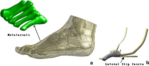
As shown in Fig. 1, the dimensions of the FE model were developed by the reconstruction of a 3D CT of the left foot of a male subject (age 28, height 176 cm and weight 72 kg). Coronal CT images were taken with space intervals of 2 mm in the neutral unloaded position. The images were segmented using MIMICS 8.0 (Materialise, Leuven, Belgium) to obtain the boundaries of the skeleton and tendon surface. The geometry of the skeletal and tendon components was processed using Solidworks 2005 (SolidWorks Corporation, Massachusetts, USA) to form solid models. Each component was then imported into Geomagic StudioTM (Geomagic, Inc., Research Triangle Park, NC, USA) to smooth the uneven surface caused by the stacking of the medical images before being assembled into a whole foot model. It was then imported into the FE package ANSYS (version 9.0) to build the numerical model. The whole foot model consisted of 28 foot bony segments, including tibia, fibula, talus, calcaneus, cuboid, navicula, three cuneiforms, five metatarsals and 14 components of the phalanges. A total 68 ligaments were considered and the plantar fascia was also included. To ensure the alignment of the exterior surfaces of the assembly model, cartilage was created using boolean operations by adding (or subtracting) one object with another to connect the bones and fill the cartilaginous space. Link elements that have only tension function capability were used to simulate ligaments bearing the tension load. The insertion and original sites of ligaments were determined based on their anatomical locations by reference to an anatomy book [25]. As fifth metatarsal injuries are more likely linked to the inversion injuries [26], two specific tendons, three ligaments and slip fascia connected to the fifth metatarsal were developed to investigate more mechanical responses of this structure (Fig. 1) in detail. All the materials were considered isotropic and linearly elastic except for the soft tissues that were described by nonlinear elastic behaviour with material properties adopted from previous literature [18, 27]. The Young’s modulus which ranged between 50 and 500 MPa were assigned to the lateral slip plantar fascia to investigate the effect of its stiffness on deformations of the fifth metatarsal. The element types and material properties used are listed in Table 1.
Fig. 1.
a The general 3D foot model. b Detailed fifth metatarsal model
Table 1.
Material properties of different parts used in the finite element model
| Component | Young’s modulus (MPa) | Poisson’s ratio | Element type |
|---|---|---|---|
| Bone | 7,300 | 0.3 | Tetrahedral solid |
| Cartilage | 1 | 0.4 | Tetrahedral solid |
| Plate | 17,000 | 0.1 | Tetrahedral solid |
| Plantar fascia | 350 | 0.4 | Tetrahedral solid |
| Slip plantar fascia | 50–500 | 0.4 | Tetrahedral solid |
| Tendon | 1,200 | 0.4 | Tetrahedral solid |
| Ligament | 260 | 0.4 | Tension-only spar |
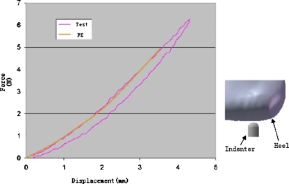
The material properties of the heel pad represent important factors which are known to be influenced largely by age, sickness, and temperature [28]. The stress–strain data on the plantar heel pad was adopted from the in vivo ultrasonic measurement results [29]. As shown in Fig. 2, the numerical results showed a good agreement with the experimental indentation test data (Fig. 2) based on a hyperelastic strain energy function:
 |
1 |
where U is the strain energy per unit reference volume, Cij and Di are material parameters (Table 2), J is the volume ratio, and I1and I2 are the first and second deviatoric strain invariants.
Fig. 2.
Development of the material model based on force–deformation data
Table 2.
The coefficients of the hyperelastic material used for the encapsulated soft tissue
| C10 | C01 | C20 | C11 | C02 | D1 | D2 |
|---|---|---|---|---|---|---|
| 0.08556 | −0.05841 | 0.03900 | −0.02319 | 0.00851 | 3.65273 | 0.00000 |
The foot–ground interaction during landing was simulated by using a foot-plate system (Fig. 3); this approach is commonly used in biomechanical modelling. In order to study the stress distribution in the metatarsals at different inversion angles, a normal force of 412 N extracted from a Kistler force platform (Kistler Inc., Zurich, Switzerland) at the initial forefoot contact during landing was applied to the inferior surface of the supporting plate, which was allowed to move in the vertical direction only. The superior surfaces of the soft tissue, distal tibia and fibula were fixed throughout the analysis. The FE model was validated by comparing the numerical results of plantar pressure to the experimental data with a Novel emed pressure platform (Novel, Munich, Germany) of controlled normal landing and inversion landing with an initial angle of proximal ten degrees. The measurement was conducted on the same subject who had volunteered for the medical image scanning. The validated FE model was then used to evaluate the effects of inversion angles on the deformation of the metatarsals by varying the approach angle of the plate. Ethical approval for the study protocol was obtained from the University Ethics Committee. Results of the FE analysis were presented in terms of von Mises equivalent stresses (σv. M.), which weight the effect of all principal stresses (σ1, σ2, σ3). Maximal principal stress was selected to represent the tensile stress within the metatarsals as it is directly relevant to the injury [30].
Fig. 3.
Different touchdown conditions. a Normal touchdown. b 10 degrees inversion. c 20 degrees inversion
Results
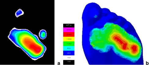
Figure 4 compared the plantar pressure distribution under inversion landing with an angle of ten degrees from the Novel emed measurement and the FE model. As shown in the contour plots, the numerically predicted pressure distribution pattern (Fig. 4b) matches well with the experimental results (Fig. 4a). A peak pressure of 292 kPa was predicted in the FE model at the lateral metatarsal head region, while the corresponding peak pressure measured by Novel emed was about 276 kPa in this region.
Fig. 4.
Plantar pressure distribution under 10 degree inverse touchdown. a Novel emed measured. b Finite element predicted
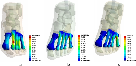
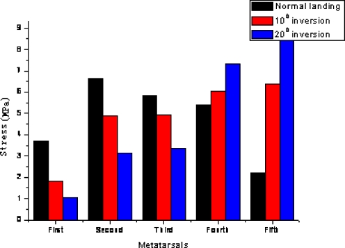
Figure 5 shows distribution of the von Mises stress (VMS) within the metatarsals during landing at different inversion angles. It clearly shows that both the overall pattern of VMS distribution and the stress concentration positions are strongly influenced by the inversion angle. As the inversion angle increased from the normal landing position to 20 degrees, the position of the peak VMS shifted from the second metatarsal to the fifth metatarsal. Figure 6 plots the peak VMS within the five metatarsals at different inversion angles. Under the normal landing condition, a large proportion of the forces are sustained by the middle metatarsal; the highest VMS is 6.65 MPa at the neck of the second metatarsal, followed by the third (5.83 MPa), the fourth (5.36 MPa), the first (3.69 MPa), and the fifth (2.21 MPa). The VMS distribution varied significantly when the plate approached the foot from an inversion position. The lateral metatarsals began to play a major role in load bearing with the peak VMS point moved to the fifth metatarsal. The peak VMS position within each metatarsal also shifted with increase of the inversion angles. As shown in Fig. 6, the forces on the lateral fourth and fifth metatarsals at an inversion landing position are significantly higher than that with the normal landing.
Fig. 5.
Stress distribution in the five metatarsals (MPa). a Normal touchdown. b 10 degrees inversion. c 20 degrees inversion
Fig. 6.
The peak von Mises stress values of the metatarsal during different touchdown conditions
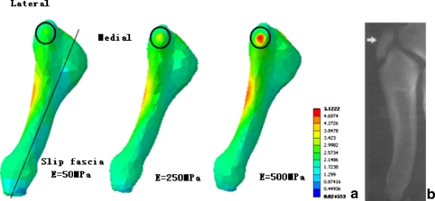
As shown by the material properties sensitivity study with a detailed model of the fifth metatarsal (Fig. 7), there was a general increase in maximal principal stress (MPS) of tuberosity with increasing Young’s modulus of the slide fascia from 50 MPa to 500 MPa. With a two-fold increase of the Young’s modulus for the slip fascia, an increase of 32% in the stress level was predicted in the tuberosity. The MPS was located on the lateral side of the proximal shaft with a soft slip fascia under inversion landing; whilst, with a stiffer slip fascia, the peak MPS appeared in the lateral aspect of the tuberosity. This result suggests that the stiffness of the slip fascia is an important factor to be considered in dealing with the fifth metatarsal avulsion fracture.
Fig. 7.
a The fifth metatarsal maximal principal stress distribution under different lateral slip fascia stiffnesses. b Typical avulsion fracture position
Discussion
Fracture of the metatarsal is one of the most common foot injuries, which is sometimes directly associated with foot orientation during landing [1]. This study shows the stress distribution (load supporting) in the metatarsals was significantly different between normal and inversion landing conditions. The changes of the stress conditions with increasing inversion angles were found to vary between each metatarsal. The stress in the lateral metatarsals increased, while medial metatarsal stresses decreased with increasing inversion angles. Peak stress concentration was found to be near the proximal part of the fifth metatarsal during inversion landing. The FE model developed represents a detailed model based on subject specified dimensions and material properties in published data previously used for modelling the deformation of the human foot. The numerical results were directly compared to biomechanical tests, which were commonly used to assess the accuracy and validity of FE models [15, 16] under controlled conditions. As shown in Fig. 4, the predicted plantar pressure distribution is comparable to the Novel emed measurement. The stress level predicted for normal landing conditions also agreed with other FE model predictions in standing and walking [15, 27].
Both the stress distribution and peak stress level have been studied, which could directly affect metatarsal injuries. As shown by the results (Figs. 5 and 6), the stresses distribution in the metatarsals for the normal landing condition and inversion conditions were significantly different. The stresses level in the second metatarsal was the highest among the metatarsals under the normal landing conditions, which may take up a large percentage of the force. This agrees with the finding that the second metatarsal was the most common of the lessor metatarsal heads to become injured [31]. The modelling results showed that the lateral metatarsal suffered higher forces than the medial ones in an inversion landing position. As shown in Fig. 5, the forefoot contact force became concentrated beneath the lateral metatarsal heads with an increased inversion angle. The VMS value in the first metatarsal decreased from 3.69 MPa to 1.06 MPa, while the stress in the fifth metatarsal increased from 2.21 MPa to 8.66 MPa as the inversion angle was increased to 20 degrees. Studies on other inversion angles showed a similar trend. The increased stress level in the lateral metatarsals under inversion conditions, in particular in the fifth metatarsal, may potentially be a factor contributing to the high incidence of lateral metatarsal injuries during inversion reported in clinical studies [1, 32]. For example, the clinical study by Ekrol and Court-Brown [1] found that 67.2% of cases among 355 patients with metatarsal injuries were in the fifth metatarsal. This suggests that the prediction of VMS using the current model is a viable method to predict the effect of the inversion angle on the stresses in the metatarsals.
From the numerical results, it is clear that the MPS concentration is in the proximal diaphyseal part of the fifth metatarsal, which corresponds well with the stress fracture position in the athletic population [4, 33]. Several research works [30, 34] have reported that the tuberosity avulsion fracture usually occurs in the fifth metatarsal as a result of an inversion injury. The MPS value in this part was not particularly high with a soft slip fascia; however, the stress level increased significantly when a higher stiffness was assigned to the slip fascia. The predicated MPS distribution pattern of the fifth metatarsal was also close to the avulsion fracture situation (Fig. 7). This suggests that the stiffness of the slip fascia is an important factor to be considered in dealing with the fifth metatarsal avulsion fracture, which is in agreement with previous research works. Richli and Rosenthal [35] suggested that the slide fascia is an important structure that affects tuberosity avulsion fracture associated with inversion and plantar flexion of the forefoot. In another study, Pao et al. [36] reported six avulsion fractures of the tip of the tuberosity and observed that the avulsed fragment occurred at the insertion site of the slide fascia. These suggest that the FE model could potentially provide a useful tool to assess the deformation of foot under extreme inversion conditions.
In summary, this work developed a detailed 3D FE foot model to investigate the effect of the inversion positions on stresses distribution and concentration within the metatarsals. The predicted plantar pressure distribution showed good agreement with experimental data of controlled biomechanical tests. The deformation and stresses of metatarsals at different inversion angles (normal landing, 10 degree inversion and 20 degree inversion angle) were comparatively studied. The results showed that in the lateral metatarsals stress increased while in the medial metatarsals stress decreased with increasing inversion angles. The peak stress point was found to be near the proximal part of the fifth metatarsal, and this is in reasonable agreement with reported clinical observations on metatarsal injuries. To simplify the analysis in this study, only one normal foot model was created which renders the results inapplicable to people with foot diseases or abnormal foot shapes. Specific foot structures such as varus hindfoot could be the subject of further research studies to investigate the injury mechanism relationship between metatarsal to abnormal foot structure.
References
- 1.Ekrol I, Court-Brown CM. Fractures of the base of the 5th metatarsal. The Foot. 2004;14:96–98. doi: 10.1016/j.foot.2003.12.007. [DOI] [Google Scholar]
- 2.Popovic N, Jalali A, Georis P, Gillet P. Proximal fifth metatarsal diaphyseal stress fracture in football players. J Foot Ankle Surg. 2005;11:135–141. doi: 10.1016/j.fas.2005.03.002. [DOI] [Google Scholar]
- 3.Milgrom C, Giladi M, Stein M, Kashtan H, Margulies JY, Chisin R. Stress fractures in military recruits. A prospective study showing an unusually high incidence. J Bone Joint Surg Br. 1985;67:732–735. doi: 10.1302/0301-620X.67B5.4055871. [DOI] [PubMed] [Google Scholar]
- 4.Logan AJ, Dabke H, Finlay D, Makwana N. Fifth metatarsal base fractures: a simple classification. J Foot Ankle Surg. 2007;13:30–34. doi: 10.1016/j.fas.2006.08.001. [DOI] [Google Scholar]
- 5.Mađarević M, Kolundžić R, Trkulja V, Mirković M, Pećina M. Biomechanical analysis of functional adaptation of metatarsal bones in statically deformed feet. Int Orthop. 2009;33(1):157–163. doi: 10.1007/s00264-008-0622-z. [DOI] [PMC free article] [PubMed] [Google Scholar]
- 6.Raikin SM, Slenker N, Ratigan B. The association of a varus hindfoot and fracture of the fifth metatarsal metaphyseal-diaphyseal junction: the Jones fracture. Am J Sports Med. 2008;36(7):1367–1372. doi: 10.1177/0363546508314401. [DOI] [PubMed] [Google Scholar]
- 7.Watson AWS. Ankle sprains in players of the field-games Gaelic football and hurling. Sports Med Phys Fitness. 1999;36:66–70. [PubMed] [Google Scholar]
- 8.Pontaga I. Ankle joint evertor–invertor muscle torque ratio decrease due to recurrent lateral ligament sprains. Clin Biomech. 2004;19:760–762. doi: 10.1016/j.clinbiomech.2004.05.003. [DOI] [PubMed] [Google Scholar]
- 9.Cock A, Clercq D, Willems T, Witvrouw E. Temporal characteristics of foot roll-over during barefoot jogging: reference data for young adults. Gait Posture. 2005;21:432–439. doi: 10.1016/j.gaitpost.2004.05.004. [DOI] [PubMed] [Google Scholar]
- 10.Grimston SK, Nigg BM, Fisher V, Ajemian SV. External loads throughout a 45-minute run in stress fracture and non-stress fracture runners. J Biomech. 1994;27:668. doi: 10.1016/0021-9290(94)90983-0. [DOI] [Google Scholar]
- 11.Bennell K, Crossley K, Jayarajan J. Ground reaction forces and bone parameters in females with tibial stress fracture. Med Sci Sports Exerc. 2004;36:397–404. doi: 10.1249/01.MSS.0000117116.90297.E1. [DOI] [PubMed] [Google Scholar]
- 12.Wright IC, Neptune RR, Bogert AJ, Nigg BM. The influence of foot positioning on ankle sprains. J Biomech. 2000;33:513–519. doi: 10.1016/S0021-9290(99)00218-3. [DOI] [PubMed] [Google Scholar]
- 13.Raspovic A, Newcombe L, Lloyd J, Dalton E. Effect of customized insoles on vertical plantar pressures in sites of previous neuropathic ulceration in the diabetic foot. The Foot. 2000;10:133–138. doi: 10.1054/foot.2000.0604. [DOI] [Google Scholar]
- 14.Bus SA, Lange A. A comparison of the 1-step, 2-step, and 3-step protocols for obtaining barefoot plantar pressure data in the diabetic neuropathic foot. Clin Biomech. 2005;20:892–899. doi: 10.1016/j.clinbiomech.2005.05.004. [DOI] [PubMed] [Google Scholar]
- 15.Gefen A, Megido-Ravid M, Itzchak Y, Arcan M. Biomechanical analysis of the three-dimensional foot structure during gait: a basic tool for clinical applications. J Biomech Eng. 2000;122:630–639. doi: 10.1115/1.1318904. [DOI] [PubMed] [Google Scholar]
- 16.Chen WP, Tang FT, Ju CW. Stress distribution of the foot during mid-stance to push-off in barefoot gait: a 3-D finite element analysis. Clin Biomech. 2001;16:614–620. doi: 10.1016/S0268-0033(01)00047-X. [DOI] [PubMed] [Google Scholar]
- 17.Cheung JT, Zhang M, An K. A 3-dimensional finite element model of the human foot and ankle for insole design. Arch Phys Med Rehabil. 2005;86:353–358. doi: 10.1016/j.apmr.2004.03.031. [DOI] [PubMed] [Google Scholar]
- 18.Wu LJ. Nonlinear finite element analysis for musculoskeletal biomechanics of medial and lateral plantar longitudinal arch of Virtual Chinese Human after plantar ligamentous structure failures. Clin Biomech. 2007;22:221–229. doi: 10.1016/j.clinbiomech.2006.09.009. [DOI] [PubMed] [Google Scholar]
- 19.Gefen A. Plantar soft tissue loading under the medial metatarsals in the standing diabetic foot. Med Eng Phys. 2003;25:491–499. doi: 10.1016/S1350-4533(03)00029-8. [DOI] [PubMed] [Google Scholar]
- 20.Gu YD, Li JS. Finite element analysis of the instep fatigue trauma in the high-heeled gait. World J Model Simul. 2005;2:117–122. [Google Scholar]
- 21.Yu J, Cheung JT, Fan Y, Zhang Y, Leung AK, Zhang M. Development of a finite element model of female foot for high-heeled shoe design. Clin Biomech. 2008;23:31–38. doi: 10.1016/j.clinbiomech.2007.09.005. [DOI] [PubMed] [Google Scholar]
- 22.Erdemir A, Viveiros ML, Cavanagh PR (2003) A numerical experimental approach for characterising subject specific hyperelastic properties of the heel pad. In: Proceedings of the American Society of Mechanical Engineers Summer Bioengineering Conference. Key Biscayne, FL
- 23.Goske S, Erdemir A, Petre M, Budhabhatti S, Cavanagh PR. Reduction of plantar heel pressures: Insole design using finite element analysis. J Biomech. 2006;39:2363–2370. doi: 10.1016/j.jbiomech.2005.08.006. [DOI] [PubMed] [Google Scholar]
- 24.Jacob S, Patil MK. Stress analysis in three-dimensional foot models of normal and diabetic neuropathy. Front Med Biol Eng. 1999;9:211–227. [PubMed] [Google Scholar]
- 25.Platzer W (2002) Color atlas and textbook of human anatomy locomotor system, 5th ed. Thieme, New York
- 26.Clapper M, O’Brien T, Lyons P. Fractures of the fifth metatarsal: analysis of a fracture registry. Clin Orthop. 1995;315:238–241. [PubMed] [Google Scholar]
- 27.Cheung JTM, Zhang M, An K, Fan YB. Three-dimensional finite element analysis of the foot during standing—a material sensitivity study. J Biomech. 2005;38:1045–1054. doi: 10.1016/j.jbiomech.2004.05.035. [DOI] [PubMed] [Google Scholar]
- 28.Ledoux WR, Blevins JJ. The compressive material properties of the plantar soft tissue. J Biomeca. 2007;40:2975–2981. doi: 10.1016/j.jbiomech.2007.02.009. [DOI] [PubMed] [Google Scholar]
- 29.Lemmon D, Shiang TY, Hashmi A, Ulbrecht JS, Cavanagh PR. The effect of insoles in therapeutic footwear: a finite element approach. J Biomech. 1997;30:615–620. doi: 10.1016/S0021-9290(97)00006-7. [DOI] [PubMed] [Google Scholar]
- 30.Lehman R, Torg J, Pavlov H, DeLee J. Fractures of the base of the fifth metatarsal distal to the tuberosity: a review. Foot Ankle. 1987;7:245–252. doi: 10.1177/107110078700700406. [DOI] [PubMed] [Google Scholar]
- 31.Weinfeld SB, Haddad SL, Myerson MS. Metatarsal stress fractures. Clin Sports Med. 1997;16:319–338. doi: 10.1016/S0278-5919(05)70025-9. [DOI] [PubMed] [Google Scholar]
- 32.LaBella CR. Common acute sports-related lower extremity injuries in children and adolescents. Clin Pediat Emerg Med. 2007;1:31–42. doi: 10.1016/j.cpem.2007.02.010. [DOI] [Google Scholar]
- 33.Torg JS, Balduini FC, Zelko RR. Fractures at the base of the fifth metatarsal distal to the tuberosity: classification and guidelines for non-surgical and surgical management. J Bone Joint Surg. 1984;66:209–214. [PubMed] [Google Scholar]
- 34.Zelko AR, Torg JS, Rachun A. Proximal diaphyseal fractures of the fifth metatarsal-treatment of the fractures and their complications in athletes. Am J Sports Med. 1979;7:95–101. doi: 10.1177/036354657900700205. [DOI] [PubMed] [Google Scholar]
- 35.Richli WR, Rosenthal DJ. Avulsion fractures of the fifth metatarsal: experimental study of patho-mechanics. Am J Roentgenol. 1984;145:889–891. doi: 10.2214/ajr.143.4.889. [DOI] [PubMed] [Google Scholar]
- 36.Pao D, Keats T, Dussault R. Avulsion fracture of the base of the fifth metatarsal not seen on conventional radiography of the foot: the need for an additional projection. AJR Am J Roentgenol. 2000;175:549–552. doi: 10.2214/ajr.175.2.1750549. [DOI] [PubMed] [Google Scholar]


