

Abstract
We have designed and fabricated a microneedle array with electrical functionality with the final goal of electroporating skin’s epidermal cells to increase their transfection by DNA vaccines. The microneedle array was made of polymethylmethacrylate (PMMA) by micromolding technology from a master PDMS mold, followed by metal deposition, patterning using laser ablation, and electrodeposition. This microneedle array possessed sufficient mechanical strength to penetrate human skin in vivo and was also able to electroporate both red blood cells and human prostate cancer cells as an in vitro model to demonstrate cell membrane permeabilization. A model to predict the effective volume for electroporation with respect to applied voltages was constructed from finite element simulation. This study demonstrates the mechanical and electrical functionalities of the first MEMS-fabricated microneedle array for electroporation, designed for DNA vaccine delivery.
Keywords: microneedle, electroporation, micromolding, laser ablation, DU145
Introduction
Gene therapy and DNA vaccination have been investigated over two decades as alternative methods to treat human diseases where conventional approaches are less effective (Rice et al. 2008; Verma and Weitzman 2005). The goal of gene therapy/DNA vaccination is to deliver genes into target cells, such that the delivered gene can modify gene expression or stimulate immune response. Traditionally, viral vectors such as retroviruses and adenoviruses have been used to transfer the gene of interest to target cells (Verma and Weitzman 2005). Although these vectors can be extremely efficient at producing expression, problems of low virus titer, induction of strong immune responses, and significant toxicity have led to the search for alternative approaches, which do not use viral vectors, such as lipoplexes, polymeric nanoparticles, microinjection, ultrasonication, laser irradiation, and electroporation (Mehier-Humbert and Guy 2005; Niidome and Huang 2002). Among these methods, electroporation is attractive as an alternative to viral gene delivery because of the site-specific nature of delivery as well as minimized side effects.
Electroporation refers to the phenomenon of increasing permeability of the cell membrane when the cell is exposed to a short and strong electric field, enabling molecules that are cannot normally cross the cell membrane to be delivered into the cell (Jaroszeski et al. 2000). Mechanistically, electroporation occurs when a lipid bilayer membrane achieves a transmembrane voltage of hundreds of millivolts, which drives ions and associated water into the low dielectric interior of the lipid bilayer, thereby causing a rearrangement of the bilayer structure (Weaver 2000). The resulting metastable pores permit transport of molecules by electromigration during the electric pulse and by diffusion during the transient pore lifetime afterwards. Electroporation has been used to enhance chemotherapy (Mir et al. 1995), gene transfection (Aihara and Miyazaki 1998), sterilization (Sale and Hamilton 1967), protein insertion into cell membranes (Mouneimne et al. 1990), cell-cell fusion (Mekid and Mir 2000), and transdermal drug delivery (Prausnitz et al. 1993).
Among those applications, DNA vaccination through skin is attractive, because skin is easily accessible and has a large population of antigen presenting cells such as Langerhans cells, and dendritic cells that can process and present the antigen to appropriate lymphocytes efficiently (Glenn et al. 2003). In addition to that, epidermal cells slough off after a relatively short life span, thereby eliminating the bulk of the foreign DNA from the patient’s body(Williams 2003). This may help to lower the real or perceived risk of negative long-term effects of transfecting cells with foreign DNA.
To obtain efficient gene transfer in the skin, it is necessary to overcome two barriers. One is the stratum corneum, a layer of dead tissue protecting the living cells underneath, and the other is the cell membrane. To overcome the stratum corneum barrier, hypodermic needles have conventionally been used to introduce DNA into skin, although other methods have also been explored (Mitragotri 2005). Intradermal injection is painful, requires expert and unreliable injection technique and generated sharp, biohazardous medical waste (Laurent et al. 2007). As mentioned before, the cell membrane barrier can be overcome by different approaches, and electroporation is one of the promising ways. To electroporate cells in the skin, an electric field is typically applied by either plate-type electrodes (Zhang et al. 2002) or needle-type electrodes (Babiuk et al. 2002). This approach causes pain during needle insertion for DNA administration and application of high electric field due to stimulation of nerves. It can also damage tissue during electroporation due to high electric current (Prausnitz 1996). In addition to those issues, generation of the large electric field strength needed for electroporation requires application of high voltage ranging from several hundred volts to several thousand volts depending on the gap between electrodes.
Electroporation using microneedle arrays offers an attractive approach to overcoming these issues (King and Walters 2003), as shown schematically in Fig. 1. In this approach, electrically active microneedles are coated with DNA vaccine. The microneedles serve two functions: first, they administer the vaccine locally into the epidermis and superficial dermis and, second, they serve as microelectrodes that locally electroporate cells in the skin to promote DNA uptake. The short length and close spacing of the microneedles localizes the electric field in the upper skin, reduces the required voltage needed to achieve the large electric field strength needed for electroporation, and minimizes pain and tissue damage.
Fig. 1.
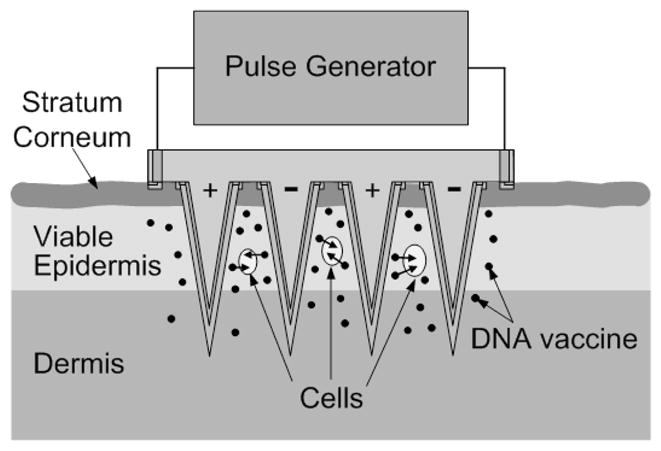
Conceptual representation of electrically active microneedle array for DNA vaccination. Microneedles coated with vaccine are inserted into the skin, thereby depositing the vaccine in the epidermis and upper dermis in a minimally invasive and targeted way. The electrical functionality of the microneedles is then utilized to apply short electric pulses to the skin, thereby electroporating resident cells and promoting intracellular uptake and expression of DNA.
Passive microneedle arrays have been developed for minimally invasive delivery of drugs and vaccines, including DNA vaccines, into the skin (Prausnitz and Langer 2008; Prausnitz et al. 2009). Electrically active microneedles arrays have studied as gel-free skin electrodes, neural tissue interfaces and biochemical sensor (Griss et al. 2001; Park et al. 2007; Rousche et al. 2001). Recently it has been demonstrated that electrically functional microneedle arrays could deliver a smallpox DNA vaccine into skin by electroporation (Hooper et al. 2007). However, that system was hand built, which is not suitable for mass manufacturing. To address this limitation, a novel approach to MEMS microfabrication is needed make microneedle arrays with sufficient mechanical strength to insert into skin, appropriate electrical functionality to electroporate cells, and simple fabrication methods to enable inexpensive mass production.
In this paper, we present the fabrication of an electrically active microneedle array using micromolding and laser ablation techniques, and the analysis of mechanical and electrical functionality. Due to its small size, the microneedle array was successfully inserted into skin without device failure and with no pain reported by human subjects. Moreover, the high electric field strength required for electroporation of red blood cell and human prostate cancer cell was achieved at relatively low voltages.
Experimental Methods
Skin insertion test
The back of the hand of a human subject was cleaned with 70 % isopropyl alcohol. A sterilized microneedle array was placed on the back of the hand, and pushed into the skin by gentle force using the investigator’s thumb. After the removal of the microneedle array, a blue dye (gentian violet, Humco, Texarkana, TX) was applied to the skin to staining the sites of microneedle penetration. The skin was washed after 1 min and then examined under the microscope (model SZX12, Olympus America, Center Valley, PA). The microneedle array was also examined for structural integrity under the microscope after the test. Subjects were asked to qualitatively assess the level of pain caused by microneedle insertion. This protocol was approved by the Georgia Tech Institutional Review Board (IRB).
Cell preparation
Red blood cell pellets were prepared from bovine blood in Alsever’s anticoagulant solution (Rockland, Gilbertsville, PA) by centrifugation (1000×g, 10 min, Beckman GS-15R, Beckman Coulter, Fullerton, CA). Human prostate cancer cells (DU145, American Type Culture Collection, Manassas, VA) were grown on T-150 flasks (BD Falcon, Franklin Lakes, NJ) as a monolayer in RPMI-1640 medium (Cellgro, Mediatech, Herndon, VA) supplemented with 10% (v/v) penicillin-streptomycin (Cellgro, Mediatech, Herndon, VA) and 10% (v/v) heat inactivated fetal bovine serum (Atlanta Biologicals, Atlanta, GA) in a humidified condition of 5% CO2 at 37°C. The cells were harvested, centrifuged, and resuspended in RPMI-1640 at a concentration of 2.5×10⁶ cells/ml using the protocol described previously (Canatella et al. 2001).
Electroporation apparatus and protocols
Electroporation apparatus
To apply an electric field, a high voltage pulser (BTX ElectroCell Manipulator 600, Genetronics, San Diego, CA) was connected to the microneedle array. The system supplied voltages ranging from 10 V to 2.5 kV with an exponential decay waveform. The pulse length was adjusted by changing the resistance and capacitance of the system. The actual voltage and the pulse length delivered by the system was measured by an oscilloscope (TDS 2014B, Tektronix, Beaverton, OR) connected to the system.
Red blood cell electroporation
The microneedle array was connected to the electroporation apparatus and affixed to a surface with the microneedles facing up. For each electroporation experiment, 25 μl of red blood cell pellet was pipetted as a hemispherical droplet onto the microneedle array. After pulse application, the pellet was pipetted off the microneedle device and placed in a microcentrifuge tube. An additional 1 ml phosphate buffered saline (PBS) was added to the tube and centrifuged at 735×g for 5 min. After centrifugation, 700 μl of the supernatant was collected to quantify the amount of hemoglobin released from the red blood cells due to electroporation using absorption spectroscopy. A negative control was prepared by repeating this procedure but without the application of the electrical pulse. A positive control was also prepared by adding 1 ml deionized water to 25 μl of red blood cell pellet to cause osmotic rupture of all cells (Alberts et al. 2002).
Unlike electroporation in a cuvette, where the volume fraction affected by an external electric field is 100%, the effective volume for electroporation (i.e., the volume where the electric field is applied if the fringing field is neglected) in the red blood cell pellet droplet applied to the microneedle array was approximately 6 μl of the 25 μl sample. This is because the droplet was taller and wider than the microneedle array. To compensate for this volume difference, the effective number of cells exposed to electroporation has been calculated based on the 6 μl volume. All experimental conditions were repeated three times to generate triplicate data points. Two identical microneedle arrays were used to perform the electroporation experiments. The arrays were washed with PBS between each electroporation experiment.
DU145 electroporation
DU145 human prostate cancer cells were prepared at a concentration of 2.5×10⁶ cells/ml. Calcein (Molecular Probes, Eugene, OR), a green fluorescent molecule that cannot cross intact cell membranes, was used to quantitatively monitor the transport of molecules into viable cells. Prior to electroporation, calcein at a final concentration of 30 μM was added to the cell suspension and homogeneously mixed by gentle vortexing. A volume of 6 μl of this suspension was applied as a hemispherical droplet over the microneedle array. After applying voltages of 10–50 V for 2.5 ms (exponential decay time constant), the cells were collected in microcentrifuge tubes. For each experimental condition, 10 experiments were performed and pooled to collect enough cells for analysis. After electroporation, the samples were incubated in a water bath at 37 °C for 10 min, which allowed the cells to recover, and were then washed with PBS and centrifuged (3500×g, 5 min, Eppendorf, Westbury, NY) three times to remove extracellular calcein in the supernatant. The subsequent cell pellets were resuspended in a final volume of 200 μl of PBS containing 15 μM propidium iodide (Invitrogen, Carlsbad, CA), a viability marker that stains nonviable cells with red fluorescence.
Data analysis
Absorption spectroscopy
Absorption spectroscopy was used to determine how much hemoglobin was released from red blood cells by electroporation. A spectrophotometer (SpectraMax Plus 384, Molecular Devices, Sunnyvale, CA) was used to measure the absorbance at 575 nm, and the amount of hemoglobin released after electroporation was quantified as a percentage of total hemoglobin in positive control.
Flow cytometry
Flow cytometry was used to determine molecular uptake, i.e., fraction of cells containing intracellular calcein, and loss of cell viability by detecting the fluorescence intensity from calcein and propidium iodide, respectively, on a cell-by-cell basis. A BD LSR benchtop flow cytometer (BD Biosciences, San Jose, CA) was used to measure the fluorescence of cells with calcein uptake and to distinguish viable from nonviable cells by the red fluorescence of propidium iodide. Each analysis sampled approximately 20,000 cells using methods described previously (Canatella et al. 2001).
Multi-photon microscopy
Cell imaging was carried out at room temperature using a Zeiss LSM 510 multiphoton microscope (Zeiss, Thornwood, NY) with an oil-immersion lens of 40× magnification. Five microliters of cell sample was placed on a 25 mm glass microscope cover slip (Fisher Scientific, Waltham, MA).
Electric field simulation
The distribution of the electric field strength generated by the microneedle array was estimated using a finite element model (FEMLAB 3.1, COMSOL, Stockholm, Sweden). For simplicity, the model consisted of 4 X 4 microneedle array, and the fringing electric field generated at the boundary of the model was neglected. To generalize the result, an arbitrary potential was applied between microneedle electrodes and the volume fraction corresponding to a certain electric field strength was determined to generate a histogram of the electric field distribution. The data were normalized by the nominal field strength by dividing the applied voltage by the edge-to-edge spacing between neighboring microneedle electrodes at their base. This normalizes the data relative to the theoretical field strength generated by parallel plate electrodes with the same spacing, thereby enabling direct comparison between the microneedle array and parallel plates in terms of the electric field distribution. After normalization, the distribution was estimated by curve fitting using Gaussian functions to generate an analytical expression.
Device fabrication
The fabrication process consists of three steps: 1) fabrication of a master structure using photolithography and reactive ion etching; 2) replication of polymeric microneedle arrays from the master structure using micromolding; 3) implementation of electrical functionality to the microneedle arrays using laser ablation and electrodeposition.
Fabrication of the master structure
The master structure was fabricated by reactive ion etching of a tapered SU-8 tower array by adapting methods described previously (Choi et al. 2007). Briefly, a first layer of SU-8 (100 μm thick) was formed on a chromium patterned (circular clear field, 150 μm in diameter) glass substrate (Fig. 2a) using the standard UV exposure process for SU-8. A second layer of SU-8 (500 μm thick) was spun on the glass substrate, and the tapered SU-8 tower array was defined by exposing UV light from the backside of the glass substrate (Fig. 2b). After simultaneous development of both SU-8 layers, the SU-8 structure was sharpened by reactive ion etching, resulting in the formation of a sharp-tipped SU-8 microneedle array (Fig. 2c). Analysis by scanning electron microscopy showed that the final structure contained a 16×16 array of microneedles with 3.5 μm tip radius of curvature, 70 μm base diameter and 350 μm height with a center-to-center spacing of 250 μm between microneedles (Fig. 2d).
Fig. 2.
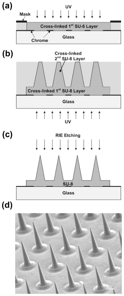
Fabrication of a microneedle master structure. (a) Definition of microneedle substrate using standard UV crosslinking of SU-8 photoresist. (b) Deposition of second SU-8 layer and UV exposure from the backside to define tapered SU-8 structures, followed by simultaneous development of both SU-8 layers. (c) Reactive ion etching to sharpen tips. (d) Scanning electron micrograph of the fabricated SU-8 master structure containing an array of 256 microneedles each measuring 350 μm in height.
Fabrication of electrically active microneedle arrays
A flexible polydimethylsiloxane (PDMS) mold was copied from the SU-8 master structure by adapting methods described previously (Park et al. 2005). Briefly, the master was placed in a polystyrene (PS) container (2.5 cm × 2.5 cm × 0.3 cm, L ×W × H), and 1.5 g of PDMS (Sylgard 184, Dow Corning, Midland, MI) was poured into the container and cured at 50°C in a conventional oven for 10 h (Fig. 3a). The PDMS mold was then separated by peeling away from the master using tweezers.
Fig. 3.

Fabrication of an electrically active microneedle array. (a) PDMS casting onto the master structure to form an inverse PDMS mold. (b) Solvent-casting of PMMA into the PDMS mold to form a replicate PMMA microneedle array. (c) Deposition of Ti/Cu layer on the PMMA microneedle array followed by laser ablation of the metal layer to form electrical isolation. (d) Electrodeposition of Ni to enhance mechanical rigidity. (e) Formation of electrical interconnects by drilling micro-vias from the backside and filling the holes with silver paste. (f) Optical micrograph of the fabricated 16 by 16 microneedle array occupying a total footprint of 0.15 cm2. The height of the microneedles is approximately 400 μm, bottom diameter is 110 μm, tip diameter is 15 μm, and center-to-center distance between microneedles is 250 μm. Lower image shows laser-ablated electrical isolations under greater magnification
To produce microneedles using the PDMA micromold, PMMA powder (MW=75,000 Da, Scientific Polymer Products, Ontario, NY) was dissolved (20% by weight) in ethyl lactate (Acros Organics, Morris Plains, NJ), which is a relatively low toxicity solvent compared to many other PMMA solvents and has been used in food additives (Aparicio and Alcalde 2009). The solution was then cast into the PDMS mold (Fig. 3b) and left at room temperature for 30 min to allow the solution to spread over the mold. After that, the sample was placed on a hot plate at 50 °C in a chemical hood to evaporate the solvent. After trying several different temperatures below the boiling point of the solvent, we found that evaporation below 50 °C avoided bubble formation. After evaporating the solvent, the sample was annealed at 100 °C in an oven for 1 h, and cooled down to room temperature. The PMMA microneedle array was then separated from the mold.
This micromolding technique can be used to fabricate microneedles from a variety of materials (Park et al. 2005). In this work, PMMA was chosen as the molding material, because it has been safely used in medical devices approved by the U.S. Food and Drug Administration (FDA) and has been widely employed in MEMS processes (Becker and Gartner 2008; Tao and Desai 2005). An additional advantage of the molding approach is its inherent mass-producibility, which is important for ultimate applications using disposable microneedle devices. The more cumbersome process of making a master structure using conventional photolithography processing can be leveraged to make many micromolds, which are each able to make many replicate microneedle devices.
To realize electrical functionality, deposition of a seed layer of metal (Ti/Cu, 300 Å/3000 Å) on the microneedle array was performed using DC sputtering (CVC Products, Rochester, NY). The seed layer was patterned by excimer laser ablation (Resonetics, Nashua, NH) to isolate adjacent microneedle rows with a 100 μm gap (Fig. 3c). Usually the excimer laser is used to machine polymers, but we found that thin metal films can also be ablated by the excimer laser. The process parameters used in this work were as follows: 248 nm wavelength, 200 mJ energy, 25% power attenuation, 100 μm/sec scribing speed. After isolation, a 20 μm thick Ni layer was electrodeposited using a commercialize Ni plating bath (10 mA/cm2, 2 h, Technic, Cranston, RI) at room temperature with stirring to enhance structural rigidity (Fig. 3d). To establish electrical connection between the microneedle array and external electroporation electronics, we designed a backside contact so as not to interfere with insertion of the microneedles into skin. To achieve this contact, a via was formed from the backside of the PMMA substrate using a CO2 laser (LS500 Laser Engraving System, New Hermes-Gravograph, Duluth, GA). Copper wire was then passed through the via and connected to the underside of the metallization using silver paste (Think & Tinker, Palmer Lake, CO) followed by an epoxy (Loctite, Rocky Hill, CT) mechanical connection (Fig. 3e). Fig. 3f shows the final fabricated device containing a 16×16 array of electrically active microneedles, with adjacent microneedle rows electrically isolated.
Experimental Results
Skin insertion test
Our electrically active microneedle array was designed to be used for DNA vaccine delivery in the skin. To achieve this goal, the microneedle device should enable DNA delivery to overcome the two barriers of stratum corneum and the cell membrane. Therefore, the microneedles should be mechanically strong enough to be inserted into skin without breakage while maintaining electrical functionality.
We first determined if non-coated (polymer-only) PMMA microneedles were strong enough to insert into skin. A microneedle array was placed on the back of the hand of a human subject and pressed against the skin by the investigator’s thumb. Subsequent microscopic examination showed that polymer-only microneedle arrays could not penetrate into human skin, but were deformed as shown in Fig. 4a.
Fig. 4.

Microneedle insertion in human skin in vivo. (a) Photomicrograph of a bare PMMA microneedle array after insertion into human skin. The microneedles did not penetrate into skin and were severely deformed. (b) Photomicrograph of human skin after piercing with an electrically active microneedle array (same geometry as in Fig. 3f) and staining with blue dye. (c) Scanning electron micrograph of a microneedle array coated with a 20 μm thick Ni layer after 3 insertions into human skin. Tissue debris is shown on the surface of intact microneedles.
To correct this problem, we noted that the conductive metal coating applied to microneedle to give electrical functionality could also be used to increase mechanical strength. Although a much thinner coating would be sufficient for electroporation, we prepared PMMA microneedles coated with either 10 μm or 20 μm thick electrodeposited Ni layers and tested them for insertion into the skin of human subjects using the same protocol. Microscopic examination showed that both coating thicknesses provided sufficient mechanical strength for insertion. However, some tips on the microneedles with a 10 μm-thick Ni layer were bent after multiple insertions, indicating that accumulated fatigue and applied lateral forces on the microneedles during multiple insertions could induce mechanical failure. This was of concern, even though microneedles are envisioned to be single-use device for DNA vaccine applications,
Microneedles with a 20 μm-thick Ni layer did not show any evidence of mechanical failure after multiple insertion tests. Upon removal from skin, the skin was stained with a dye and then imaged by microscopy. Fig. 4b shows the stained skin in the pattern of the microneedle electrode array, indicating that the microneedles pierced into the skin. Subsequent microscopic examination of the arrays showed that microneedle electrode tips were not damaged, even after multiple insertions (Fig. 4c).
After microneedle insertion, subjects were asked to qualitatively assess the pain experienced during microneedle insertion. The subjects reported that it was painless.
Electroporation of red blood cells
As an initial test of microneedle array electrical functionality, an in vitro red blood cell lysis assay was performed. Upon electroporation, red blood cells rupture and release their hemoglobin into solution, which can be easily quantified by absorption spectroscopy. As shown in Fig. 5, the electrically active microneedles electroporated the red blood cells. The degree of hemoglobin release increased with pulse voltage, length and number (ANOVA, p<0.0001), consistent with known effects of electroporation (Prausnitz et al. 1993). At the strongest conditions used, 90% of the red blood cells were electroporated.
Fig. 5.

Hemoglobin released from red blood cells lysed by electroporation using an electrically active microneedle array. Three different peak voltages of 53, 108 and 173 V each were applied each using (i) 1 pulse with an exponential decay time constant τ = 0.5 ms, (ii) 3 pulses with τ = 0.5 ms, and (iii) 1 pulse with τ = 1 ms. The inter-pulse spacing for the 3-pulse experiment was 20 s. Data represent the average of n = 3 replicate experiments. Standard deviation bars are shown.
Electroporation of human prostate cancer cells
The red blood cell lysis assay showed that our microneedle electrode array can electroporate cells, but did not show if the effect to the cell membrane was reversible or irreversible. Because the ultimate application of the microneedle device is to cause reversible electroporation of living cells in the skin and thereby transfer target molecules into those cells, we next studied the ability to deliver molecules into living cells using the microneedle electrodes. We therefore electroporated DU145 human prostate cancer cells using the microneedle device and then measured intracellular uptake of calcein, a green fluorescent marker compound. To examine cell viability after electroporation, propidium iodide, a red fluorescent marker of nonviable cells, was added to samples before the analysis. We chose to use the DU145 cell line, rather than, for example, keratinocytes or fibriblasts from the skin, because we have extensive experience with this cell line and have a large database on its electroporation using parallel plate electrodes (Canatella et al. 2001).
Electroporation cell samples were imaged by multi-photon fluorescence microscopy. Reversible electroporation, as indicated by delivery of calcein into viable cells, is shown by cells with green intracellular fluorescence. Irreversible electroporation, or electroporation that otherwise caused lasting damage to cells, is shown by red fluorescent staining of nonviable cells. As shown in Fig. 6, non-electroporated cells exhibited almost no uptake or loss of viability. In contrast, electroporated cells showed increased uptake and loss of viability with increasing voltage, consistent with known effects of electroporation (Canatella et al. 2001).
Fig. 6.

Confocal micrographs of representative DU145 human prostate cancer cells after electroporation using an electrically active microneedle array at different voltages: (a) control, (b) 11 V, (c) 23 V, (d) 37 V, and (e) 50 V. In all cases, one pulse was applied with an exponential decay time constant τ = 2.5 ms. The left row presents images from the green channel showing cells with uptake of calcein and the right row presents the same images from the red channel showing nonviable cells.
To supplement microscopic imaging, flow cytometry analysis was performed to provide quantitative data. Fig. 7a presents histograms showing the distribution of cells according to their intensity of green fluorescence, which is a direct measure of calcein uptake by electroporated cells. With increasing voltage, the cell population shifted to stronger green fluorescence intensity, indicating that more calcein was delivered into more cells. These data were used to determine the fraction of cells with green fluorescence intensity greater than the background intensity of non-electroporated cells. Similar data were used to determine the fraction of nonviable cells as indicated by red fluorescence intensity due to propidium iodide staining greater than control cells.
Fig. 7.

Flow cytometry analysis of calcein uptake and cell viability after electroporation using an electrically active microneedle array at different voltages. (a) Histograms showing the representative distributions of green fluorescence, which is a measure of intracellular calcein uptake, among populations of 20,000 analyzed cells as a function of voltage. (b) Percentage of cells exhibiting calcein uptake (◾) and remaining viable (◽) as a function of voltage. Data represent the average of n = 3 replicate experiments. Standard deviation bars are shown.
As shown in Fig. 7b, the fraction of cells loaded with calcein by electroporation increased and cell viability decreased as the applied voltage increased (Fig. 7b, ANOVA, p<0.0001), which is consistent with microscopy and with our previous results using parallel plate electrodes (Canatella et al. 2001). At the strongest conditions used, 40% of cells had calcein uptake and viability was maintained at 91%. Altogether, these results indicate that our electrically active microneedle array can deliver molecules into cells by electroporation without significant viability loss. The efficiency of delivery may be improved by further optimizing parameters, including applied voltage and pulse length.
Electric field simulation
To deliver molecules into cells effectively by electroporation, it is desirable for each cell to experience the same peak transmembrane voltage. Although the electric field is unavoidably distorted due to the presence of cells, the differences in transmembrane voltage experienced by individual cells can be minimized when a homogenous external electric field is applied. However, a limitation of the microneedle array is that it generates a heterogeneous electric field due to its geometry, i.e., curved electrode surfaces, tapered microneedle shaft. Therefore, it is important to know the degree of heterogeneity of the field generated by the microneedle array, thereby characterizing the effect of this intrinsic limitation.
Fig. 8 shows the distribution of electric field strength generated by the microneedle array. The analytical expression of the distribution was given by curve fitting using two Gaussian functions with the coefficient of determination R2=0.9998 as follows:
| (1) |
where x represents electric field strength normalized by the field strength generated by an ideal parallel plate electrode (see section 2.5) and f represents the volume fraction multiplied by the normalized field strength. By integration of f along a given range of x, the volume fraction within the range of x can be calculated.
Fig. 8.

Distribution of the electric field strength from an electrically active micorneedle array. Data were generated by finite element modeling and the fitted model was generated by curve fitting using two Gaussian functions.
To achieve high molecular uptake while maintaining high viability, the strength of the applied electric field should be within a certain range, or “window”, depending on the pulse length, cell type, and other parameters. As a representative example, we can assume that the range of electric field strength suitable for effective electroporation is from 0.5 kV/cm to 1 kV/cm, and a voltage which generates an ideal field strength of 1 kV/cm is applied. In this scenario, 42% of the cells fall within the desired electroporation field strength window, whereas 54% experience a weaker field strength and risk not being electroporated and 4% experience a stronger field strength and risk being killed. Increasing the fraction of cells within the desired window could be achieved by altering microneedle electrode device geometry to provide a more homogeneous field, picking electroporation conditions that are less sensitive to electroporation field strength and thereby enable a larger window, or other design modifications.
Discussion
DNA vaccines offer promise as a cost-effective method to immunize prophylactically and therapeutically to combat a variety of diseases (Donnelly et al. 2005; Liu 2003). However, successful vaccination in humans has been difficult, in large part due to inefficient delivery of DNA to target cells. Electroporation is well known to dramatically increase DNA transfection relative to naked DNA in vitro and in animals, and a number of animal studies have yielded positive results for DNA vaccination using electroporation (Aihara and Miyazaki 1998; Prud’homme et al. 2006). Electroporation has also been widely used in humans to facilitate intracellular delivery of chemotherapeutics in tumors with an excellent record of safety and efficacy (Gothelf et al. 2003). More recently, a Phase I trial of interleukin-12 plasmid electroporation was carried out in patients with metastatic melanoma (Daud et al. 2008).
Despite these encouraging studies, DNA vaccination would benefit from an improved electroporation device, notably one that (i) administers DNA locally in the skin, (ii) facilitates intracellular uptake of DNA by cells locally within the skin and (iii) is suitable for widespread use, including good patient acceptance and low-cost mass production. The combination of electroporation with microneedles provides an attractive solution. Microneedles coated with DNA or other compounds have been shown to efficiently target delivery into the skin for various applications (Gill and Prausnitz 2007; Widera et al. 2006; Zhu et al. 2009). Adapting the microneedles additionally to serve as microelectrodes also localizes the electric field to the skin and thereby further targets intracellular uptake of DNA by cells in the skin. Because microneedles are minimally invasive and virtually painless (Gill et al. 2008), they should be acceptable to patients; because they are simple to use, they could be employed by routine clinical personnel; and because the close needle-to-needle spacing requires only tens of volts to generate electric fields suitable for electroporation, they simplify technical requirements of the device, especially the power supply.
DNA vaccination using microneedles has been successfully demonstrated in the literature, but employed hand-built devices that are not suitable for mass production (Hooper et al. 2007). In this study, we developed a new electrically active microneedle array design and fabrication method that should be more commercially viable. Our design involves a polymer substrate that can be molded by adapting conventional micromolding technologies in widespread use. A patterned metal coating was added to serve the dual function of providing electrical activity and mechanical strength. Metallization can be carried out by DC sputtering, laser patterning and electroplating, all of which are well-established manufacturing processes. In this way, we believe that microneedle devices based on the design developed in this study can be mass produced at low cost.
Our data on device functionality show that electrically active microneedles arrays can insert into human skin and that both red blood cells and DU145 human prostate cancer cells can be efficiently electroporated. While this provides initial proof of principle, future studies will need to address electroporation of skin in vivo and delivery of DNA vaccines for increased immunogenicity.
Conclusion
This study designed and demonstrated the fabrication and molding-based replication of microneedle arrays made of polymer, coated with a metal layer, and etched to act as alternating electrodes suitable for electroporation of cells. Experiments in human subjects established that microneedle electrode arrays were strong enough to insert into skin. Additional experiments with red blood cells and human prostate cancer cells showed that these microneedle electrodes were electrically active and capable of electroporating cells with high efficiency. From finite element simulation, the distribution of the electric field strength over space was calculated, and this model can be used to explain how heterogeneity of the electric field affects the efficiency of electroporation. Overall, the device design developed in this study can provide a pathway to mass production of electrically active microneedles arrays for DNA vaccination and other applications of electroporation.
Acknowledgments
This work was supported in part by National Institute of Health. The authors would like to thank Dr. Yoonsu Choi and Dr. Jin-Woo Park for helpful discussions regarding microneedle array fabrication.
References
- Aihara H, Miyazaki J. Nat Biotechnol. 1998;16:867. doi: 10.1038/nbt0998-867. [DOI] [PubMed] [Google Scholar]
- Alberts B, Johnson A, Lewis J, Raff M, Roberts K, Walter P. Molecular Biology of The Cell. 4. Garland Science; New York: 2002. p. 627. [Google Scholar]
- Aparicio S, Alcalde R. Green Chem. 2009;11:65. [Google Scholar]
- Babiuk S, Baca-Estrada ME, Foldvari M, Storms M, Rabussay D, Widera G, Babiuk LA. Vaccine. 2002;20:3399. doi: 10.1016/s0264-410x(02)00269-4. [DOI] [PubMed] [Google Scholar]
- Becker H, Gartner C. Anal Bioanal Chem. 2008;390:89. doi: 10.1007/s00216-007-1692-2. [DOI] [PubMed] [Google Scholar]
- Canatella PJ, Karr JF, Petros JA, Prausnitz MR. Biophys J. 2001;80:755. doi: 10.1016/S0006-3495(01)76055-9. [DOI] [PMC free article] [PubMed] [Google Scholar]
- Choi Y, McClain M, LaPlaca M, Frazier A, Allen MG. Biomed Microdevices. 2007;9:7. doi: 10.1007/s10544-006-9004-8. [DOI] [PubMed] [Google Scholar]
- Daud AI, DeConti RC, Andrews S, Urbas P, Riker AI, Sondak VK, Munster PN, Sullivan DM, Ugen KE, Messina JL, Heller R. J Clin Oncol. 2008;26:5896. doi: 10.1200/JCO.2007.15.6794. [DOI] [PMC free article] [PubMed] [Google Scholar]
- Donnelly JJ, Wahren B, Liu MA. J Immunol. 2005;175:633. doi: 10.4049/jimmunol.175.2.633. [DOI] [PubMed] [Google Scholar]
- Gill HS, Denson DD, Burris BA, Prausnitz MR. Clin J Pain. 2008;24:585. doi: 10.1097/AJP.0b013e31816778f9. [DOI] [PMC free article] [PubMed] [Google Scholar]
- Gill HS, Prausnitz MR. J Control Release. 2007;117:227. doi: 10.1016/j.jconrel.2006.10.017. [DOI] [PMC free article] [PubMed] [Google Scholar]
- Glenn GM, Kenney RT, Ellingsworth LR, Frech SA, Hammond SA, Zoeteweij JP. Expert Rev Vaccines. 2003;2:253. doi: 10.1586/14760584.2.2.253. [DOI] [PubMed] [Google Scholar]
- Gothelf A, Mir LM, Gehl J. Cancer Treat Rev. 2003;29:371. doi: 10.1016/s0305-7372(03)00073-2. [DOI] [PubMed] [Google Scholar]
- Griss P, Enoksson P, Tolvanen-Laakso HK, Meriläinen P, Ollmar S, Stemme G. J Microelectromech S. 2001;10:10. [Google Scholar]
- Hooper JW, Golden JW, Ferro AM, King AD. Vaccine. 2007;25:1814. doi: 10.1016/j.vaccine.2006.11.017. [DOI] [PMC free article] [PubMed] [Google Scholar]
- Jaroszeski MJ, Heller R, Gilbert R. Electrochemotherapy, Electrogenetherapy, and Transdermal Drug Delivery. 1. Humana Press; Totowa: 2000. pp. 1–4. [Google Scholar]
- King AD, Walters RE. 6,603,998. US Patent. 2003
- Laurent PE, Bonnet S, Alchas P, Regolini P, Mikszta JA, Pettis R, Harvey NG. Vaccine. 2007;25:8833. doi: 10.1016/j.vaccine.2007.10.020. [DOI] [PubMed] [Google Scholar]
- Liu MA. J Intern Med. 2003;253:402. doi: 10.1046/j.1365-2796.2003.01140.x. [DOI] [PubMed] [Google Scholar]
- Mehier-Humbert S, Guy RH. Adv Drug Deliver Rev. 2005;57:733. doi: 10.1016/j.addr.2004.12.007. [DOI] [PubMed] [Google Scholar]
- Mekid H, Mir LM. Biochim Biophys Acta. 2000;1524:118. doi: 10.1016/S0304-4165(00)00145-8. [DOI] [PMC free article] [PubMed] [Google Scholar]
- Mir LM, Orlowski S, Belehradek J, Teissie J, Rols MP, Sersa G, Miklavčič D, Gilbert R, Heller R. Bioelectroch Bioener. 1995;38:203. [Google Scholar]
- Mitragotri S. Nat Rev Immunol. 2005;5:905. doi: 10.1038/nri1728. [DOI] [PubMed] [Google Scholar]
- Mouneimne Y, Tosi PF, Barhoumi R, Nicolau C. Biochim Biophys Acta. 1990;1027:53. doi: 10.1016/0005-2736(90)90047-r. [DOI] [PubMed] [Google Scholar]
- Niidome T, Huang L. Gene Ther. 2002;9:1647. doi: 10.1038/sj.gt.3301923. [DOI] [PubMed] [Google Scholar]
- Park IY, Li ZY, Li XM, Pisano AP, Williams RS. Biosens Bioelectron. 2007;22:2065. doi: 10.1016/j.bios.2006.09.017. [DOI] [PubMed] [Google Scholar]
- Park JH, Allen MG, Prausnitz MR. J Control Release. 2005;104:51. doi: 10.1016/j.jconrel.2005.02.002. [DOI] [PubMed] [Google Scholar]
- Prausnitz MR. Adv Drug Deliver Rev. 1996;18:395. [Google Scholar]
- Prausnitz MR, Bose VG, Langer R, Weaver JC. P Natl Acad Sci USA. 1993;90:10504. doi: 10.1073/pnas.90.22.10504. [DOI] [PMC free article] [PubMed] [Google Scholar]
- Prausnitz MR, Langer R. Nat Biotechnol. 2008;26:1261. doi: 10.1038/nbt.1504. [DOI] [PMC free article] [PubMed] [Google Scholar]
- Prausnitz MR, Lau BS, Milano CD, Conner S, Langer R, Weaver JC. Biophys J. 1993;65:414. doi: 10.1016/S0006-3495(93)81081-6. [DOI] [PMC free article] [PubMed] [Google Scholar]
- Prausnitz MR, Mikszta JA, Cormier M, Andrianov AK. In: Vaccines for Pandemic Influenza. Compans RW, Orenstein WA, editors. Springer; New York: 2009. p. 369. [Google Scholar]
- Prud’homme GJ, Glinka Y, Khan AS, Draghia-Akli R. Curr Gene Ther. 2006;6:243. doi: 10.2174/156652306776359504. [DOI] [PubMed] [Google Scholar]
- Rice J, Ottensmeier CH, Stevenson FK. Nat Rev Cancer. 2008;8:108. doi: 10.1038/nrc2326. [DOI] [PubMed] [Google Scholar]
- Rousche PJ, Pellinen DS, Pivin DP, Williams JC, Vetter RJ, Kipke DR. IEEE T Bio-Med Eng. 2001;48:361. doi: 10.1109/10.914800. [DOI] [PubMed] [Google Scholar]
- Sale A, Hamilton W. Biochim Biophys Acta. 1967;148:781. doi: 10.1016/0005-2736(68)90030-8. [DOI] [PubMed] [Google Scholar]
- Tao SL, Desai TA. Adv Mater. 2005;17:1625. [Google Scholar]
- Verma IM, Weitzman MD. Annu Rev Biochem. 2005;74:711. doi: 10.1146/annurev.biochem.74.050304.091637. [DOI] [PubMed] [Google Scholar]
- Weaver JC. IEEE T Plasma Sci. 2000;20:24. [Google Scholar]
- Widera G, Johnson J, Kim L, Libiran L, Nyam K, Daddona PE, Cormier M. Vaccine. 2006;24:1653. doi: 10.1016/j.vaccine.2005.09.049. [DOI] [PubMed] [Google Scholar]
- Williams AC. Transdermal and Topical Drug Delivery. 1. Pharmaceutical Press; London: 2003. pp. 5–14. [Google Scholar]
- Zhang L, Nolan E, Kreitschitz S, Rabussay DP. Biochim Biophys Acta. 2002;1572:1. doi: 10.1016/s0304-4165(02)00270-2. [DOI] [PubMed] [Google Scholar]
- Zhu QY, Zarnitsyn VG, Ye L, Wen ZY, Gao YL, Pan L, Skountzou I, Gill HS, Prausnitz MR, Yang CL, Compans RW. P Natl Acad Sci USA. 2009;106:7968. doi: 10.1073/pnas.0812652106. [DOI] [PMC free article] [PubMed] [Google Scholar]