

Abstract
Purpose
To describe a method for streamlining the process of elective nodal volume definition for H&N IMRT treatment planning.
Methods
Twenty patients receiving curative-intent radiation for H&N cancer underwent comprehensive treatment planning using three distinct plan design techniques; conventional three-field design (C3FD), target defined IMRT (TD-IMRT) and conformal avoidance IMRT (CA-IMRT). For each patient, the C3FD was created first, thereby providing “outermost boundaries” for subsequent IMRT design. Briefly, target definition IMRT involved physician-contouring of a GTV, CTV1, CTV2 and normal tissue avoidance structures on consecutive 1.25 mm CT images. CA-IMRT involved physician contouring of a GTV and normal tissue avoidance structures only. The overall physician time for each approach was monitored and the resultant plans were rigorously compared.
Results
The average physician working time for design of respective H&N treatment contours was 0.3 hours for the C3FD plan, 2.7 hours for TD-IMRT and 0.9 hours for CA-IMRT. Dosimetric analysis confirmed that the largest volume of tissue treated to intermediate (50 Gy) and high dose (70 Gy) occurred with C3FD followed by CA-IMRT and then TD-IMRT. However, for the two IMRT approaches comparable results were found in terms of salivary gland and spinal cord protection.
Conclusion
CA-IMRT for H&N offers an alternative to TD-IMRT. The overall time for physician contouring is substantially reduced (~3 fold) yielding a more standardized elective nodal volume. In light of the complexity of H&N IMRT target design, CA-IMRT may ultimately prove a safer and more reliable method to export to general radiation oncology practitioners, particularly those with limited H&N caseload experience.
Keywords: Head and Neck IMRT, Conformal Avoidance, Target Definition, GTV, CTV
INTRODUCTION
A major objective of intensity modulated radiation therapy (IMRT) is to spare normal tissue structures from high dose radiation. Clinical series have confirmed partial preservation of salivary function and improved quality of life in H&N cancer patients treated with IMRT as compared to those treated with C3FD (1, 2). However, the complexity of H&N target definition presents a challenge for the smooth and safe implementation of IMRT. Although high resolution CT, MRI and PET imaging can enhance tumor visualization, contouring of H&N targets remains complex and labor intensive. For elective cervical nodal regions where there exists no discrete tumor to image, the accurate, reproducible and time-efficient contouring of treatment volumes represents an even greater challenge. Guidelines and atlases to assist with H&N target volume delineation are emerging. (3-9) Despite the availability of published H&N IMRT target delineation guidelines, many practitioners do not appear to make routine use of these guidelines in their practice; even among leading H&N cancer experts around the world (10). There may be several reasons for this, including the substantial time and expertise required to perform high precision H&N target design, and the fact that the guidelines themselves are complex. Indeed, even with attention to published guidelines, there remain significant challenges to personalize target design to unique tumor and anatomic features of each individual H&N cancer patient. Current H&N IMRT treatment guidelines emphasize target delineation, which remains a labor-intensive exercise in H&N cancer.
In an effort to explore methods to simplify the IMRT planning process for H&N cancer, we have experimented with an alternative method that emphasizes “conformal avoidance” of normal tissue structures rather than the more classic target delineation method. The concept of conformal avoidance was first proposed by Mackie et al. (11) and for the treatment of H&N cancer by Aldridge et al. (12). This method of planning may prove most valuable in situations where there is uncertainty regarding tumor extension or tumor risk and where adjacent normal tissue structures are more clearly defined on imaging studies. These features commonly apply in H&N cancer and we have therefore explored the conformal avoidance paradigm in H&N IMRT with special emphasis on the design of logical elective treatment volumes.
MATERIALS AND METHODS
Patients
Twenty patients having received definitive radiation therapy for advanced H&N cancer were identified for study. Cases selected included nasopharynx, soft palate, base of tongue, tonsil, supraglottic larynx, and H&N unknown primary. All patients underwent CT imaging, with intravenous contrast, following H&N immobilization with a slice thickness of 1.25 mm. The same CT image sets were used for the generation of all plans, namely, conventional H&N radiotherapy using conformal lateral field arrangements, target defined IMRT (TD-IMRT) and conformal avoidance IMRT (CA-IMRT), respectively.
Conventional H&N Field Design
In the case of conventional H&N radiotherapy patients first underwent virtual simulation. The CT isocenter was determined and a GTV was carefully delineated. Comprehensive H&N shrinking field design (lateral large fields, off cord, and final boost), including posterior neck electron fields, was carried out using a lateral beams eye view with 2D-projection of the GTV. The regional field or CTV (appropriate nodal coverage as indicated on lateral views) was defined using anatomic boundaries dictated by the knowledge of H&N control and failure patterns established over several decades of radiotherapy (Figure 1a). This process is essentially identical to drawing treatment fields on lateral radiographs obtained from a conventional simulator. Organs at risk (OAR) are not specifically identified in this planning process since essentially all tissues contained within the lateral beam projections are treated.
Figure 1.
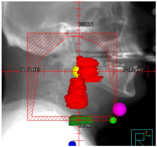
Conventional field design for a patient with T2N2b squamous cell carcinoma of the left tonsil.
Target Defined IMRT (TD-IMRT)
In target defined IMRT (TD-IMRT) the first two steps of the virtual simulation process are identical to that of conventional H&N radiotherapy. Thereafter organs at risk (OAR) are delineated, such as optic chiasm, parotid glands, spinal cord, brainstem, larynx, mandible and anterior oral cavity. During the planning process, dose objectives are placed on each OAR in an effort to diminish overall normal tissue complications.
The next step in TD-IMRT involves the definition of high risk and low risk clinical target volumes, CTV1 and CTV2, respectively. CTV1 and CTV2 are generated by identification and careful delineation of high risk and low risk nodal regions on each consecutive CT image. Once the GTV, CTV1, CTV2, and OARs are defined, appropriate planning target volumes (PTV) for each target are created by volumetric expansion. If a particular PTV overlaps an OAR, a “residual” OAR is created by subtracting the overlap between OAR and PTV. Thereafter, dose objectives are selected for all PTV and OAR (or residual OAR) targets and then the inverse planning process is initiated.
Conformal Avoidance IMRT (CA-IMRT)
In conformal avoidance IMRT (CA-IMRT) the first three steps of the virtual simulation process are identical to that of TD-IMRT. First, one identifies the CT isocenter and then delineates the GTV and OARs, which we will also refer to as conformal avoidance structures. However, in contrast to TD-IMRT, CTV1 and CTV2 are not defined by outlining individual nodal levels on consecutive CT slices for CA-IMRT. Rather, these elective targets are initially defined by simply projecting the conventional lateral treatment fields appropriate for the specific anatomical H&N tumor and stage. This represents the critical distinction between the two IMRT design methods. Rather than slice-by-slice contouring of three-dimensional nodal stations from CT anatomy, the physician simply uses his/her own conventional lateral fields as the guiding template for elective CTV design and then subtracts from this volume those normal tissue OARs where no tumor risk is present (e.g. spinal cord, parotid gland). We now describe in detail the definition of CTV1 and CTV2 using conventional lateral Head and Neck treatment field designs.
Generation of CTV1 and CTV2 using conventional lateral H&N treatment fields
This method proceeds along the following five steps. Step 1: based on several decades of collective clinical experience (13-17) the conventional lateral fields appropriate for the specific H&N cancer patient are designed. In step 2, the GTV and key conformal avoidance structures such as parotid glands and spinal cord are contoured. In step 3, a crude maximal treatment volume is generated that reflects the full lateral H&N beam coverage by selecting the 85% isodose line as a hypothetical prescription line. Step 4 consists of generating a region of interest that represents the full volume of irradiation as specified by the isodose volume selected in step 3. In step 5, the final CTV is generated by subtracting avoidance structures from the region of interest, selective trimming of areas deemed not to contain lymphatic risk for tumor spread, and then dividing the resulting CTV into high risk CTV1 and low risk CTV2 as applicable. In the following section, we describe each of these five steps in greater detail.
Step 1
The first step in the CA-IMRT design process is the most familiar to practitioners of H&N radiation oncology, namely conventional lateral field design. To illustrate the CA-IMRT method, we highlight a patient with a T2 N2b M0 squamous cell carcinoma of the left tonsil. Figure 1 depicts the conventional lateral field design created for this patient.
Step 2
In step 2, the GTV and key conformal avoidance structures are contoured. The conformal avoidance structures (OARs in the case of TD-IMRT) such as the parotid glands, eyes, optic chiasm, larynx, mandible, posterior fossa, anterior oral cavity are delineated on each CT slice just as with TD-IMRT. The spinal cord is drawn slightly differently, since, we aim to conformally avoid not only the spinal cord but also the spinal column, which harbors minimal risk for H&N cancer spread, we have decided to approximate the spinal column by an inverted U-shape that includes the spinal cord, the vertebral body and paraspinal muscles. One first draws this inverted U-shape on 7 to 9 representative transverse CT-slices through out the volume, and the spinal column conformal avoidance region is then generated through interpolating between these 7 to 9 inverted U-shaped contours (cf. Figure 2). Skin (defined as 4 mm thick ring) is also defined as an avoidance structure. Figure 2 shows several of these conformal avoidance structures as defined.
Figure 2.
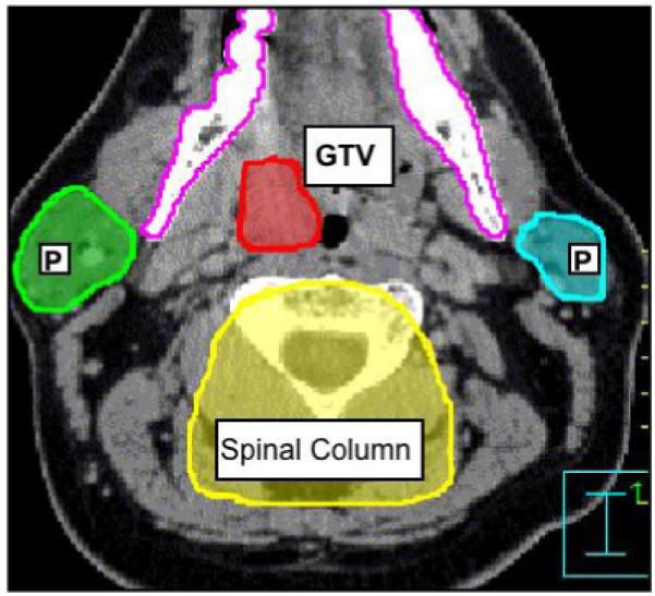
Contouring of the GTV and the conformal avoidance structures for a patient with squamous cell carcinoma of the left tonsil. OAR shown are the parotid glands (P), mandible, and spinal column.
Step 3
In order to initiate definition of an elective nodal treatment volume, we then generate a pre-optimized treatment volume by employing the conventional lateral fields designed in step 1 of this process. By selecting the 85% isodose line, we generously approximate the prescription volume commonly chosen for H&N cancer patients treated with conventional lateral beam techniques (90–100% common at most institutions).
Step 4
Following selection of the 85% isodose line, the preliminary volume for CA-IMRT is generated as follows. The upper and lower contours of the elective nodal volume are coincident with the superior and inferior field borders as indicated by the 85% isodose line on the sagittal view. One can approximate the shape of 85% isodose line in the sagittal view quickly by drawing additional contours in locations where the gradient of the 85% isodose line changes in the sagittal view. Interpolating between these contours then generates the entire elective nodal volume (cf. Figure 3). However, some treatment planning systems allow one to directly convert an isodose volume into contours and this feature can then be used, instead of above described contouring procedure, to generate the preliminary volume for CA-IMRT.
Figure 3.
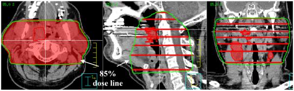
The contouring of the elective nodal volume as indicated by 85% isodose volume is shown.
Step 5
Next one subtracts all avoidance structures from the elective nodal volume. This yields the raw elective nodal volume shown in Figure (4A). One then proceeds to generate the residual total elective nodal volume shown in Figure (4B) by first trimming away the part of the raw elective nodal volume that lies on the outside of the mandible next the fingers around the avoidance structures that are generated when these structures are subtracted from the raw elective nodal volume are trimmed away. This residual total elective nodal volume should not simply be accepted as is, but should be carefully reviewed slice by slice and if necessary adjusted and modified according to disease site and nodal involvement, and such that it contains the entire GTV.
Figure 4.

Definition of total CTV.
Once one has arrived at a satisfactory residual total elective nodal volume, high risk and low risk clinical target volumes are designed as follows. First one divides the residual elective nodal volume into two parts: a high risk and low risk nodal volume (cf. Figure 4B) using the appropriate contouring tool. Doing the following then generates a separate high-risk CTV1 and low risk CTV2. One first generates a copy of the divided residual clinical target volume. The high-risk CTV1, is then obtained by deleting all contours that are part of the low risk nodal volume form one of the copies of the divided residual elective nodal volume. The low risk CTV2 is obtained by subtracting the high risk CTV1 from the remaining intact copy of the divided residual elective nodal volume. The remaining intact copy of the divided residual elective nodal volume can then be deleted, since it has been split into a high risk CTV1 and low risk CTV2.
RESULTS
Uniformity of contouring
Whereas contouring of the GTV for H&N cancer should be patient specific, class solutions can be employed in the design of elective target volumes. For the majority of advanced stage H&N cancer patients, bilateral neck nodal stations II-V require coverage. In this study, greater variation in CTV contours was observed with the TD-IMRT method not only across patients, but also between neighboring CT slices of the same patient, (Figure 5A depicts irregular borders of the contoured CTV). This variation in CTV contouring was reduced using the CA-IMRT method, as shown in Figure 5B, which shows more regular and smooth CTV borders.
Figure 5.

Additional examples of clinical target volumes contoured using the CAD methods on patients with tumor arising from supraglottic larynx (A), nasopharynx (B).
Contoured volumes and resulting isodose volumes
The same GTV definition and dose grid was employed in the generation of the conventional lateral H&N fields, the TD-IMRT and CA-IMRT treatment plans. The specific GTV shape varied depending on the size of primary tumor and the number of grossly involved lymph nodes. Table 1 shows the differences in CTV definition between the TD-IMRT and CA-IMRT for all 20 patients. As can be seen from Table 1 the final CTVs derived from the CA-IMRT method were always somewhat larger than those derived using the TD-IMRT method (cf. Table 1, column 2). To see if the same is true for the prescription isodose clouds surrounding the GTV and CTV their volumes (i.e. the dose volumes encircling these structures receiving the intended prescribed minimal peripheral dose) were generated and compared for all methods considered.
Table 1.
Volume and dose comparisons for H&N cancer field design using conventional, TD-IMRT and CA-IMRT design techniques
| Method | Drawn CTV (cm3) |
GTV Isodose Volume (cm3) |
60 Gy Isodose Volume (cm3) |
CTV Isodose Volume (cm3) |
Maximum cord dose |
Mean parotid dose |
|---|---|---|---|---|---|---|
| Conventional | -- | 421 | 566.0 | 838.8 | 49.1 | 63.2 |
| TD-IMRT | 350.2 | 123.3 | 371.1 | 627.9 | 40.0 | 20.8 |
| CA-IMRT | 579.4 | 138.0 | 421.4 | 699.4 | 39.8 | 22.1 |
GTV dose for conventional fields was prescribed to 70 Gy/2 Gy x 35 fractions and 69.1 Gy/2.1 Gy x 33 fractions;
CTV dose was prescribed to 50 Gy/2 Gy x 25 fractions for conventional fields and 54 Gy/1.64 Gy x 33 fractions.
As expected, the conventional H&N lateral field arrangement generated the largest prescription isodose volumes for the GTV (Table 1, column 3). Note that with the conventional lateral H&N shrinking field technique, the GTV resides within a final cone down boost that yields a high dose volume extending essentially from one side to other (i.e., cheek to cheek). The prescription isodose volume for the GTV was significantly decreased using either the TD- or the CAD-IMRT method. The prescription isodose volumes for the GTV using TD-IMRT and CAD-IMRT were 28% and 31% respectively of the prescription isodose volume for the GTV derived when using a conventional lateral field arrangement. However, this was not true for comparisons regarding the CTVs across the 3 planning techniques. Indeed, although the physician-designed CTVs were approximately 1.6 fold larger using the CAD-IMRT than the TD-IMRT method, the resulting average prescription isodose volumes surrounding the CTVs were not significantly different (cf. Table 1, column 4). Specifically, the volume of the TD-CTV prescription isodose cloud and the CAD-CTV prescription isodose cloud were 74.6% and 82.3% respectively of the prescription isodose cloud volume of the elective nodal region resulting from the conventional field arrangement. In fact the average volumes of the CTV isodose clouds for the TD- and the CAD-IMRT method were respectively 663.0 cm3 and 694.2 cm3 (P > 0.05, for a 2-tailed T-Test). This shows that even though the CTV is defined more tightly when the TD-IMRT method is employed as when the CAD-IMRT method is employed (Figures 6A and 6B) the volume of the prescription isodose clouds needed to cover the TD-contoured CTV is virtually the same as that for the CAD-IMRT method (Figure 7B and Figure 7C). As one can see from the sagittal and coronal views in Figures 7A to Figure 7C, the 54Gy isodose line is almost identical for the TD- and CAD-IMRT plan (Figure 7B and 7C) and the nodal coverage is comparable to that indicated by the 50 Gy isodose line in the conventional field arrangement shown in Figure 7A. This shows that both methods ultimately yield highly comparable nodal coverage (see also Figure 8A in this respect). However, the CAD-IMRT approach yields a more regular and smooth elective nodal volume as it does not rely on the delineation of ill-defined nodal planes but on the delineation of a regional field that is defined by decades of clinical H&N experience and well-defined normal structures.
Figure 6.

Comparison of clinical target volumes that have been drawn using the TD-IMRT and CAD-IMRT method.
Figure 7.

Comparison of dose distributions of the conventional field arrangement (CFA) (A), target defined IMRT (TD-IMRT) (B) conformal avoidance defined IMRT (CAD-IMRT) (C).
Figure 8.


DVH comparisons for TD-IMRT, CAD-IMRT), and the corresponding CFA.
Organ at Risk Sparing
To compare OAR sparing using the different treatment plans, the mean dose to the spared parotid gland and maximum dose to the spinal cord were calculated and compared for each treatment plan, respectively. For both OARs, the same dose objectives were used in the inverse planning optimization of TD-IMRT and CA-IMRT. Significant sparing of parotid gland well below the 24 Gy parotid mean dose suggested by Eisbruch (18) for salivary gland preservation was demonstrated for either TD-IMRT or CA-IMRT (cf. Table 1). The difference between achieved parotid mean does was not statistically significant (P > 0.05, for a 2-tailed T-Test). The maximum spinal cord dose was reduced for both TD-IMRT and CA-IMRT (cf. Table 1 and Figures 8A-C). While this analysis has concentrated on the dose received by the spared parotid gland and the spinal cord other conformal avoidance structures (e.g. pharyngeal muscles, laryngeal cartilage, carotids, etc.) also need to be considered to ensure that they are not sites at which dose dumping occurs.
Overall CTV contouring time
The overall contouring time required for the CA-IMRT method was significantly reduced when compared to the overall contouring time required for the TD-IMRT method. GTV and the normal structure contouring is identical for both methods, with times spent ranging from 30–60 minutes (depending on complexity of the GTV). The overall contouring time for the CTV employing the CA-IMRT method was approximately one third of that required using the TD-IMRT method. The CTV contouring time for the CA-IMRT method ranged from 25–50 minutes (average 38 minutes), while the CTV contouring time for the TD-IMRT method ranged form 35–145 minutes (average 85 minutes). Time needed to generate a complete conventional field design ranged from 25–40 minutes.
DISCUSSION
H&N IMRT represents a significant advance in the technology of H&N cancer treatment. However the IMRT design process presents a significant challenge for the radiation oncology clinician in light of the labor-intensive and complex nature of target delineation. Although the contouring of normal anatomic structures and GTV itself is time intensive, with the aid of high-resolution imaging, this process can be readily accomplished. The greater challenge with regard to consistent target delineation is the time-efficient and reliable delineation of elective nodal target volumes. There are several reasons why elective target contouring presents particular challenges. First, the elective nodal regions are essentially normal anatomic regions at risk, defined by fat/lymphatic spaces between muscles. Accurate definition of these regions is often challenging due to a lack of consistent anatomical reference landmarks from patient to patient. It is not uncommon to see significant variation between elective nodal contours for successive CT-slices of the same patient where the anatomy is almost identical. Further, appreciation of the perceived “risk” areas differs widely among clinicians. This factor can create significant variations in CTV contouring across physicians, institutions, and even between patients treated by the same physician. Finally, questions remain regarding optimal margins for elective nodal volumes since tight margins combined with the steep IMRT dose gradients can lead to underdosing or even geographic miss of regions that may contain tumor. The CA-IMRT technique builds directly upon the conventional H&N lateral field design that has served as the basis for treating H&N cancer patients over several decades.(13-17) The conformal avoidance paradigm enables clinicians to create an elective nodal volume in a safe and efficient manner, since the contouring of normal tissue structures are more reproducible across physicians compared with the contouring of elective nodal risk regions. This method therefore strives to reduce the impact of uncertainty in elective nodal volume definition.
Despite similarities between these planning methods, there are important distinctions. The need to contour the OAR and GTV is the same for both, and therefore the time spent on this is identical. However, the definition of clinical target volumes that correspond to elective nodal treatment is distinct. First, by using an isodose volume generated from conventional H&N lateral field design the uncertainties in the delineating the CTV boundaries is reduced. This initial target volume takes direct advantage of prior decades of experience with patterns of success and failure in H&N radiotherapy. For clinicians who trained using 2D simulation techniques for H&N cancer, this method provides a direct link to established H&N field design experience as they initiate experience with H&N IMRT. It is important to note that, although the derived CTV volumes are somewhat different for two contouring methods, the final prescription isodose volume for elective irradiation is highly comparable (Table 1, columns 2 and 5). This suggests that the labor-intensive H&N TD-IMRT method may not provide a distinct advantage over the simplified CA-IMRT method in sparing normal tissues in terms of achieved prescription dose volumes.
The CA-IMRT method commences with a volume derived from conventional H&N lateral field arrangements. Broad experience with conventional H&N field design suggests that the majority of recurrences are in-field at primary bulk tumor sites or within involved nodal stations. Marginal recurrences with appropriate H&N field design are infrequent. (19) Further, in reports in which IMRT has been employed as the primary treatment modality for head and neck cancer, in-field recurrences at known primary tumor sites and involved nodal stations again dominate the treatment failures (20-24) Therefore, properly designed conventional H&N lateral fields should adequately encompass high-risk areas. The CA-IMRT design method takes full advantage of this extensive clinical experience (13-17) by incorporating lateral field design as the initial cornerstone for subsequent IMRT refinement. New users can therefore, directly link their own H&N cancer experience and training as they initiate CA-IMRT, rather than adopt a completely new set of anatomic target guidelines without direct linkage to their own experience using conventional H&N lateral field arrangements.
Conclusion
The CA-IMRT approach may prove particularly valuable to radiation oncologists who treat a small number of H&N cases and thus maintain less routine familiarity with complex H&N anatomic issues. The CA-IMRT approach is more time-efficient for the physician in that normal tissue structures are more readily defined on imaging studies and are therefore, easier to contour reproducibly than less well-defined elective nodal or “at risk” regions. The overall time for physician contouring is reduced approximately 3 fold in the CA-IMRT approach. Moreover, it was found that salivary gland and spinal cord sparing is comparable between the CA-IMRT and TD-IMRT approach.
For safety and effectiveness in H&N cancer patient care, a bridge between the traditional design of conventional lateral H&N radiation fields and the use of IMRT is needed. The CA-IMRT design technique represents such a bridge for the radiation oncologist. Indeed, based on the remarkable heterogeneity in H&N target design among worldwide H&N cancer experts (10), the CA-IMRT design method may in fact promote more uniform treatment practice habits across all practitioners. This would in turn contribute to our ability to execute controlled clinical trials with H&N IMRT.
Acknowledgments
Supported in part by NIH grant R01 CA109656 and P01 CA88960-01
Footnotes
Publisher's Disclaimer: This is a PDF file of an unedited manuscript that has been accepted for publication. As a service to our customers we are providing this early version of the manuscript. The manuscript will undergo copyediting, typesetting, and review of the resulting proof before it is published in its final citable form. Please note that during the production process errors may be discovered which could affect the content, and all legal disclaimers that apply to the journal pertain.
Conflict of Interest: None
References
- 1.Eisbruch A, Kim HM, Terrell JE, Marsh LH, Dawson LA, Ship JA. Xerostomia and its predictors following parotid-sparing irradiation of head-and-neck cancer. Int J Radiat Oncol Biol Phys. 2001;50:695–704. doi: 10.1016/s0360-3016(01)01512-7. [DOI] [PubMed] [Google Scholar]
- 2.Chao KS, Deasy JO, Markman J, Haynie J, Perez CA, Purdy JA, et al. A prospective study of salivary function sparing in patients with head-and-neck cancers receiving intensity-modulated or three-dimensional radiation therapy: initial results. Int J Radiat Oncol Biol Phys. 2001;49:907–916. doi: 10.1016/s0360-3016(00)01441-3. [DOI] [PubMed] [Google Scholar]
- 3.Nowak PJ, Wijers OB, Lagerwaard FJ, Levendag PC. A three-dimensional CT-based target definition for elective irradiation of the neck. Int J Radiat Oncol Biol Phys. 1999;45:33–39. doi: 10.1016/s0360-3016(99)00049-8. [DOI] [PubMed] [Google Scholar]
- 4.Martinez-Monge R, Fernandes PS, Gupta N, Gahbauer R. Cross-sectional nodal atlas: a tool for the definition of clinical target volumes in three-dimensional radiation therapy planning. Radiology. 1999;211:815–828. doi: 10.1148/radiology.211.3.r99jn40815. [DOI] [PubMed] [Google Scholar]
- 5.Wijers OB, Levendag PC, Tan T, van Dieren EB, van Sornsen de Koste J, van der Est H, et al. A simplified CT-based definition of the lymph node levels in the node negative neck. Radiother Oncol. 1999;52:35–42. doi: 10.1016/s0167-8140(99)00076-6. [DOI] [PubMed] [Google Scholar]
- 6.Eisbruch A, Foote RL, O’Sullivan B, Beitler JJ, Vikram B. Intensity-modulated radiation therapy for head and neck cancer: emphasis on the selection and delineation of the targets. Semin Radiat Oncol. 2002;12:238–249. doi: 10.1053/srao.2002.32435. [DOI] [PubMed] [Google Scholar]
- 7.Chao KS, Wippold FJ, Ozyigit G, Tran BN, Dempsey JF. Determination and delineation of nodal target volumes for head-and-neck cancer based on patterns of failure in patients receiving definitive and postoperative IMRT. Int J Radiat Oncol Biol Phys. 2002;53:1174–1184. doi: 10.1016/s0360-3016(02)02881-x. [DOI] [PubMed] [Google Scholar]
- 8.Gregoire V, Daisne JF, Geets X, Levendag P. Selection and delineation of target volumes in head and neck tumors: beyond ICRU definition. Rays. 2003;28:217–224. [PubMed] [Google Scholar]
- 9.Levendag P, Nijdam W, Noever I, Schmitz P, van de Pol M, Sipkema D, et al. Brachytherapy versus surgery in carcinoma of tonsillar fossa and/or soft palate: late adverse sequelae and performance status: can we be more selective and obtain better tissue sparing? Int J Radiat Oncol Biol Phys. 2004;59:713–724. doi: 10.1016/j.ijrobp.2003.11.032. [DOI] [PubMed] [Google Scholar]
- 10.Hong TS, Tome WA, Chappell RJ, Harari PM. Variations in target delineation for head and neck IMRT: An international multi-institutional study. Int J Radiat Oncol Biol Phys. 2004;60(Supplement 1):S457. [Google Scholar]
- 11.Mackie TR, Holmes TW, Reckwerdt PJ, Yang J. Tomotherapy - Optimized Planning and Delivery of Radiation-Therapy. International Journal of Imaging Systems and Technology. 1995;6:43–55. [Google Scholar]
- 12.Aldridge JS, Harari PM, Reckwerdt PJ, Olivera GH, Tomé WA, Fink M, et al. Conformal avoidance Tomotherapy in the treatment of Head and Neck cancer. Int J Radiat Oncol Biol Phys. 1999;45(Supplement 1):S245. [Google Scholar]
- 13.Hinerman RW, Mendenhall WM, Morris CG, Amdur RJ, Werning JW, Villaret DB. Postoperative irradiation for squamous cell carcinoma of the oral cavity: 35-year experience. Head Neck. 2004;26:984–994. doi: 10.1002/hed.20091. [DOI] [PubMed] [Google Scholar]
- 14.Hinerman RW, Mendenhall WM, Morris CG, Amdur RJ, Werning JW, Villaret DB. T3 and T4 true vocal cord squamous carcinomas treated with external beam irradiation: a single institution’s 35-year experience. Am J Clin Oncol. 2007;30:181–185. doi: 10.1097/01.coc.0000251368.57302.cc. [DOI] [PubMed] [Google Scholar]
- 15.Mendenhall WM, Morris CG, Hinerman RW, Malyapa RS, Amdur RJ. Definitive radiotherapy for nasopharyngeal carcinoma. Am J Clin Oncol. 2006;29:622–627. doi: 10.1097/01.coc.0000248895.90193.7e. [DOI] [PubMed] [Google Scholar]
- 16.Mendenhall WM, Morris CG, Amdur RJ, Hinerman RW, Werning JW, Villaret DB. Definitive radiotherapy for squamous cell carcinoma of the base of tongue. Am J Clin Oncol. 2006;29:32–39. doi: 10.1097/01.coc.0000189680.60262.eb. [DOI] [PubMed] [Google Scholar]
- 17.Mendenhall WM, Morris CG, Amdur RJ, Hinerman RW, Malyapa RS, Werning JW, et al. Definitive radiotherapy for tonsillar squamous cell carcinoma. Am J Clin Oncol. 2006;29:290–297. doi: 10.1097/01.coc.0000209510.19360.f9. [DOI] [PubMed] [Google Scholar]
- 18.Eisbruch A, Ten Haken RK, Kim HM, Marsh LH, Ship JA. Dose, volume, and function relationships in parotid salivary glands following conformal and intensity-modulated irradiation of head and neck cancer. Int J Radiat Oncol Biol Phys. 1999;45:577–587. doi: 10.1016/s0360-3016(99)00247-3. [DOI] [PubMed] [Google Scholar]
- 19.Pigott K, Dische S, Saunders MI. Where exactly does failure occur after radiation in head and neck cancer? Radiother Oncol. 1995;37:17–19. doi: 10.1016/0167-8140(95)01584-4. [DOI] [PubMed] [Google Scholar]
- 20.Dawson LA, Anzai Y, Marsh L, Martel MK, Paulino A, Ship JA, et al. Patterns of local-regional recurrence following parotid-sparing conformal and segmental intensity-modulated radiotherapy for head and neck cancer. Int J Radiat Oncol Biol Phys. 2000;46:1117–1126. doi: 10.1016/s0360-3016(99)00550-7. [DOI] [PubMed] [Google Scholar]
- 21.Chao KS, Ozyigit G, Tran BN, Cengiz M, Dempsey JF, Low DA. Patterns of failure in patients receiving definitive and postoperative IMRT for head-and-neck cancer. Int J Radiat Oncol Biol Phys. 2003;55:312–321. doi: 10.1016/s0360-3016(02)03940-8. [DOI] [PubMed] [Google Scholar]
- 22.Yao M, Chang K, Funk GF, Lu H, Tan H, Wacha J, et al. The failure patterns of oral cavity squamous cell carcinoma after intensity-modulated radiotherapy-the university of iowa experience. Int J Radiat Oncol Biol Phys. 2007;67:1332–1341. doi: 10.1016/j.ijrobp.2006.11.030. [DOI] [PubMed] [Google Scholar]
- 23.Schoenfeld GO, Amdur RJ, Morris CG, Li JG, Hinerman RW, Mendenhall WM. Patterns of failure and toxicity after intensity-modulated radiotherapy for head and neck cancer. Int J Radiat Oncol Biol Phys. 2008;71:377–385. doi: 10.1016/j.ijrobp.2007.10.010. [DOI] [PubMed] [Google Scholar]
- 24.Sanguineti G, Gunn GB, Endres EJ, Chaljub G, Cheruvu P, Parker B. Patterns of locoregional failure after exclusive IMRT for oropharyngeal carcinoma. Int J Radiat Oncol Biol Phys. 2008;72:737–746. doi: 10.1016/j.ijrobp.2008.01.027. [DOI] [PubMed] [Google Scholar]