Abstract
Flexible, tip-steerable needles promise to enhance physicians’ abilities to accurately reach targets and maneuver inside the human body while minimizing patient trauma. Here, we present a functional needle steering system that integrates two components: (1) a patient-specific 2D pre- and intra-operative planner that finds an achievable route to a target within a planar slice of tissue (Stochastic Motion Roadmap), and (2) a low-level image-guided feedback controller that keeps the needle tip within that slice. The planner generates a sequence of circular arcs that can be realized by interleaving pure insertions with 180° rotations of the needle shaft. This preplanned sequence is updated in realtime at regular intervals. Concurrently, the low-level image-based controller servos the needle to remain close to the desired plane between plan updates. Both planner and controller are predicated on a previously developed kinematic nonholonomic model of bevel-tip needle steering. We use slighly different needles here that have a small bend near the tip, so we extend the model to account for discontinuities of the tip position caused by 180° rotations. Further, during large rotations of the needle base, we maintain the desired tip angle by compensating for torsional compliance in the needle shaft, neglected in previous needle steering work. By integrating planning, control, and torsion compensation, we demonstrate both accurate targeting and obstacle avoidance.
I. INTRODUCTION
Accurate insertion of needles is a key component of many medical diagnoses and treatments. Poor needle tip placement can result in misdiagnosis of biopsies or suboptimal radiation delivery in procedures such as prostrate brachytherapy. Feedback control of the needle inside tissue promises to reduce targeting errors and thereby mitigate contusions by requiring fewer needle insertions. The aim of needle steering is to accurately guide the tip of a flexible needle to a target while avoiding obstacles along the path.
When performing manual needle insertions, physicians and surgeons depend on tactile feedback from the tool or a 2D medical image of it and surrounding tissue. Steerable needles are controlled from the base of the needle and are a highly underactuated nonholonomic system [1], requiring extraordinary spatial reasoning to manually control. Romano et al. [2] compared manual teleoperation to automatic needle insertion and showed that hybrid control provided improved accuracy. Rather than taking over the entire needle insertion process, systems like the one we present will be of most benefit when they are used to assist the physician in visualization, planning, and control.
Several methods have been developed to steer a needle in tissue. DiMaio and Salcudean [3] showed that a stiff needle can be steered inside soft tissue by moving the external base of the needle. They numerically calculated a Jacobian matrix to relate base motions to needle tip motions. Glozman and Shoham [4] similarly steered needles and modeled the local tissue deformations as a system of springs.
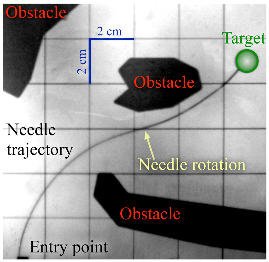
Another approach to steering uses a flexible needle with a bevel tip. Such a needle will bend as it is inserted into tissue at a constant curvature. Webster et al. [1] developed and validated a nonholonomic model of a highly flexible needle steered in tissue by using the asymmetry of a bevel tip. In the model, the needle tip acts like a small bicycle with “locked” handlebars so the needle follows a circular arc on a plane. The direction of curvature is controlled by changing the orientation of the bevel; using the needle shaft as a flexible drive shaft, rotating the base of the needle from outside the tissue rotates the bevel at the needle tip. Pre-bent needles, either alone [5] or in combination with bevel tips [6], have also been used to achieve needle steering. An example path is shown in Figure 1. For a survey that includes needle steering in deformable soft tissue, see [7].
Fig. 1.
An example path of a flexible steerable needle with one 180° base rotation. Here the needle avoids the obstacles and reaches the target.
Several methods have been developed for path planning for steerable needles. Park et al. [8] numerically computed a needle path to reach a target in 3D space using diffusion-based motion planning. This planner was built on previous work by Zhou et al. that compensated for noise bias [9] and modeled dead-reckoning error for nonholonomic mobile robots [10]. Alterovitz et al. [11], [12] developed planners that consider needle steering with motion uncertainty and obstacles in the workspace.
As part of a larger collaborative needle steering project1 between Johns Hopkins University, University of California at Berkeley, and Queen’s University, these experiments represent the first time that planning and control have been integrated into a working flexible needle steering system. We present a functional needle steering system that integrates patient-specific 2D pre- and intra-operative planning to find an achievable route to a percutaneous target within a planar slice of tissue [12], and a low-level image-guided feedback controller to enforce the 2D constraint that the needle remain within that slice [13], [14]. Both planner and controller are based on the previously developed kinematic model of needle steering [1]. This is also the first work to account for discontinuities in the needle path arising from the use of pre-bent tips.
II. SYSTEM MODULES
The planner, controller, and torsion compensator were developed separately with assumptions about the functions of the other components. The path planner is only concerned with steering the needle in a plane, assuming the needle tip will stay on a plane. The controller is only concerned with maintaining the needle in a plane. Together, the path planner and controller are able to specify and control the full 6 DOF pose of the needle. The torsion compensator helps transition the roll state (axial rotation) of the needle during bevel flips. In this section we discuss the function of each individual module and then explain how they work together.
A. Motion Planning in a 2D Plane
The goal of motion planning is to compute high-level actions that will guide the needle to a target while avoiding obstacles. In the case of needle steering in the plane, the high-level actions correspond to inserting the needle a small fixed distance in the bevel-right or the bevel-left direction. The bevel direction is a simplifying abstraction for planar problems that collapses the continuous roll angle of the needle into a binary state.
For many problems, there are many feasible paths a needle could take to reach a target while avoiding the obstacles. Following a shortest path to the target may require passing through narrow corridors between obstacles where a slight deflection from the intended path could result in collision with an obstacle. Alternatively, we use a planner that considers uncertainty in the needle’s motion and seeks to maximize the probability that the needle’s path will avoid obstacles and reach the target.
The planner used in our needle steering system is based on the Stochastic Motion Roadmap (SMR), a motion planning framework that explicitly considers uncertainty in robot motion to maximize the probability of success [12]. The method requires as input polygonal outlines of the obstacles on the imaging plane, the start location, and a target location. The method then builds a roadmap by first sampling obstacle-free states in the configuration space. Using the kinematic model of steerable needles and an uncertainty model of needle motion [12], the method locally samples possible outcomes for each high-level action to estimate state transition probabilities between the states. Given a target location, we use the roadmap to formulate a Markov Decision Process (MDP), which we solve using Infinite Horizon Dynamic Programming to compute a stochastically optimal plan. Once the roadmap has been constructed and the MDP solved, the optimal next action for any current needle configuration can be obtained instantaneously. This capability enables the SMR planner to be used inside a feedback loop in the integrated needle steering system.
In our experiments, we assume the needle is inserted on the x–y plane and define the workspace as a 2D rectangle with dimensions xmax by ymax. Obstacles in the workspace are defined by (possibly nonconvex) polygons and the target region is defined by a circle with center point (tx, ty) and radius rt.
B. Image-Based Control to Stay in the 2D Plane
It has been observed in simulations and experiments that any small initial deviation in needle angle causes the needle to diverge from the 2D plane. To maintain the needle “height”—the distance from the desired plane—in the experiments performed here, we used the controller–observer pair presented in [13], [14] to drive the needle tip to a desired 2D plane. The control law guides the axial angle of the needle using only the measured distance of the needle tip from the plane of interest.
The imaging system (stereo-cameras in our experimental setup, but eventually bi-plane fluoroscopy or 3D ultrasound in the operating room) can be used to directly measure the needle tip position inside the tissue. We use an observer to estimate the tip orientation since the thin needle orientation cannot be directly measured. It has been shown that to drive the needle tip to a desired plane, only three of the six DOFs (distance away form the desired plane, pitch away form the plane, and roll of the needle) need to be considered to achieve the task [13], [14]. This “task-induced” reduction enabled the design of the observer and controller for a simpler and lower dimensional system. Furthermore, this can be exploited to design a linear observer for the other three states of the system (yaw and the two translation degrees of freedom in the desired 2D plane).
C. Torsion Compensation During 180° Bevel Flips
The kinematic model of needle steering [1] used for the above planner and controller does not account for the “lag” between the base angle and tip angle caused by torsional friction at the needle–tissue interface and torsional compliance of the needle. This effect is substantial during the 180° rotations the motion planner commands (bevel flips). Recent work by Reed [15] shows a lag as high as 40° for a needle inserted 10 cm into a phantom tissue similar to the one used for our experiments. Even a small discrepancy is likely to result in poor performance or failure of the path planner and image-guided controller.
For the experiments performed here, we are using a friction compensation algorithm for bevel flips (180° rotations) that puts the needle in a reasonable state for further insertion. This compensator axially rotates the needle at its base several times so that the tip and base angles are at the desired location and the needle will have a minimal amount of stored torsional energy. Without torsion compensation, subsequent insertion would release the stored energy by breaking the static friction, which could cause the needle to “unwind” in a detrimental direction. The torsion compensator is described in more detail in [15].
D. Experimental Setup
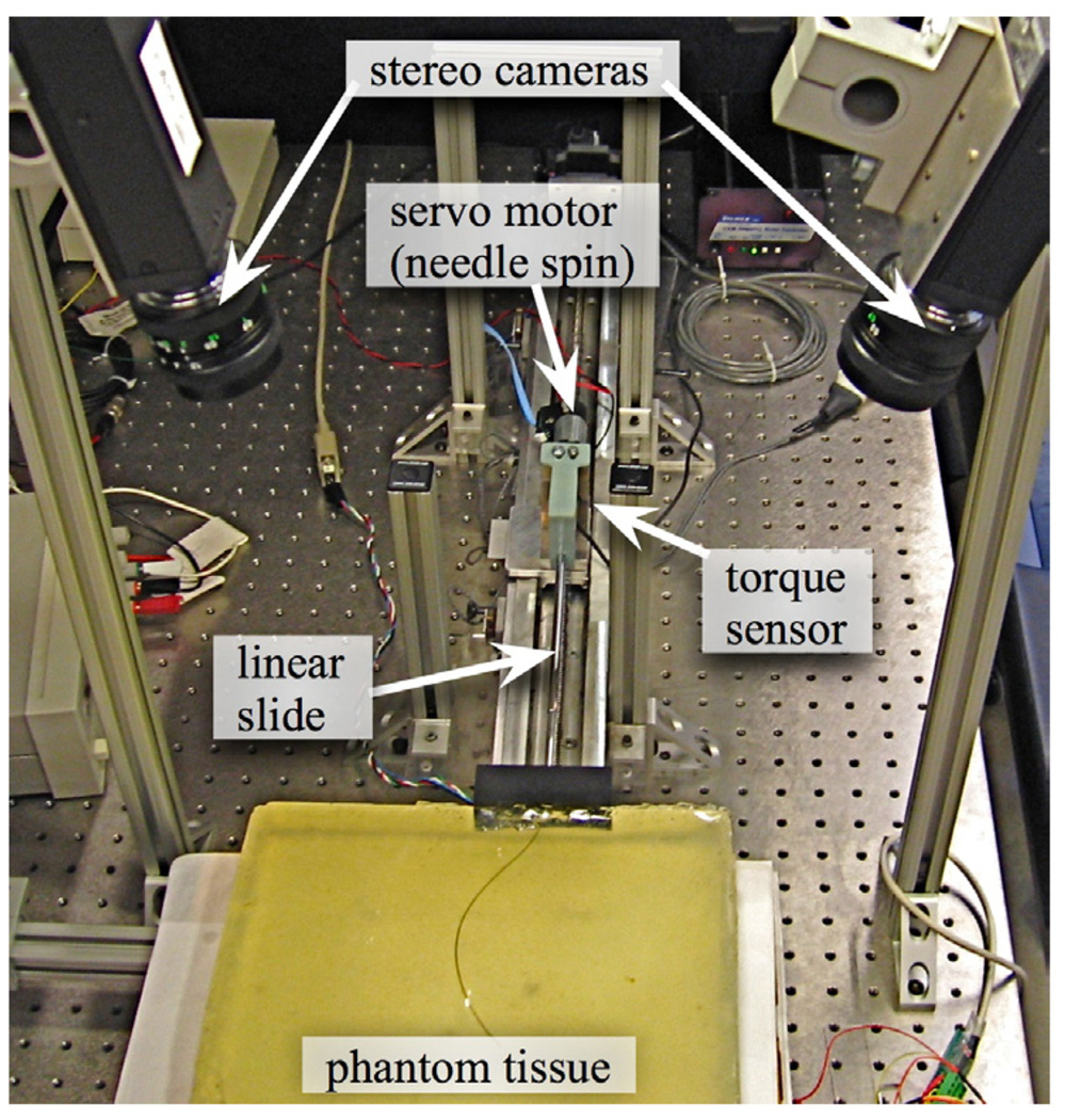
For the experiments performed here, we used the hardware shown in Figure 2, which is described in detail in [16]. We used a transparent plastisol tissue phantom (M-F Manufacturing Co., Inc., Fort Worth, TX) manufactured from plastic and softener in a ratio of 4:1. The needle was a 0.61mm diameter nitinol wire (Nitinol Devices and Components, Fremont, CA, USA). The needle tip had a bevel angle of roughly 45° and had a 15° pre-bend in a complimentary direction. There was a 12mm straight section of the needle between the pre-bend and the tip. The radius of curvature was experimentally determined to be 6.1 cm.
Fig. 2.
Experimental setup shown with stereo cameras, insertion control, rotation control, and torque sensor.
The insertion was controlled by a linear slide with a stepper motor. The rotation was controlled with a DC servo motor. A telescoping support sheath prevented the needle from buckling during insertion. Tracking was performed by a pair of XCD-X710 firewire cameras (Sony Corporation, Tokyo, Japan) mounted above the phantom tissue.
III. MODULE INTEGRATION
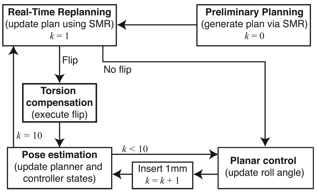
Each module of the system operates at a different level and with different timing. Figure 3 provides an overview of how each of the modules interact.
Fig. 3.
State-flow diagram. The estimator–planar controller pair operates at 1mm intervals; the estimator estimates the needle tip orientation from the tip position measurements and the planar controller maintains the needle tip near the desired plane. The planner operates at 1 cm intervals and decides the bevel direction. If the planner commands a direction change, then the torsion compensator ensures that the entire needle is rotated by 180°. k is a counter that corresponds to insertion distance.
A. High Level Planning
The path planner operates at the highest level, computing the optimal path to reach the target. The path planner is queried at regular intervals after every 1 cm of insertion, which can be adjusted as necessary. At each query, the planner is provided with the needle tip’s current position and orientation, (x, y, ϕ), and bevel direction, left or right. The planner returns the optimal next action, which can be to either insert the needle 1 cm bevel-right or 1 cm bevel-left. This action is computed so that the needle will follow a path that maximizes the probability of successfully avoiding the obstacles and reaching the target. The bevel-left or bevel-right command is sent to the torsion compensator and the planar controller.
B. Low-Level Estimator–Controller Pair
The controller plus state estimator operates at a low level, and is updated every 1 mm. Real-time tracking of the needle tip provides (x, y, z) positions of the needle tip. The height (z) measurements are noisy since the tip is triangulated from two cameras with noise and limited resolution. An encoder can read the angle at the base of the needle, but not at the tip. The observer estimates the roll, pitch and yaw of the needle tip over time. After each 1 mm advancement, the controller adjusts the angle of the needle base to guide the needle to the desired plane. The controller is unconcerned with the position and yaw (x, y, ϕ) within the desired 2D plane; that is the job of the higher level planner. Likewise, the path planner is unconcerned with the height, roll, and pitch, but assumes the controller maintains them correctly.
C. Torsion Compensation
When the path planner commands a 180° bevel flip, the torsion compensator aligns the angle throughout the needle into a suitable state for the controller to continue planar tracking during subsequent 1 mm insertions. We only use the torsion compensator for the large 180° rotations since it is better suited for large rotations and the planar controller is designed to adjust for small deviations.
D. Discontinuities Due to Pre-Bent Needles
To enhance steerability (decreasing the radius of curvature of the needle), we used bevel-tip needles that also have a pre-bend in them near the tip. The use of pre-bent needles results in discontinuities in the tip position and yaw angle when the bevel changes direction. After the needle rotates 180°, the relaxed state of the pre-bent portion of the needle is offset from the previous path in the tissue. The tissue and needle settle to a minimum energy state with balanced forces. Since the tissue and needle are elastic, the needle tip can vary by as much as 4 mm in the plastisol and needle used in these experiments. The yaw angle also changes by up to 22°. We experimentally determined the tip translation and rotation discontinuities. This redirection is perpendicular to the insertion axis, which violates the nonholomomic model of the needle used in the path planner and the planar controller. In certain cases, this discontinuity could cause the needle to shift into an obstacle since the planner would predict a continuous curve around the obstacle.
The SMR planner requires a precise specification of the kinematics of the needle. We extended the kinematic model in the motion planner presented in [12] to accommodate discontinuities in the path and the angle at the needle tip. The new kinematic model requires 3 parameters: the needle radius of curvature, a displacement offset for when the bevel/pre-bend direction is changed, and an orientation angle offset for when the bevel/pre-bend direction is changed.
IV. RESULTS
We performed experiments to test the integration of the system modules and new kinematic model. We defined a rectangular workspace with dimensions xmax = 12 cm and ymax = 12 cm with 3 polygonal obstacles and a circular target of radius rt = 0.5 cm at location (tx, ty) = (11 cm, 9 cm). For the motion planner’s kinematic model of the needle, we specified a needle radius of curvature of 6.1 cm and set the displacement offset to 0.3 cm and the angle offset to 22° for the discontinuity at bevel/pre-bend direction changes. We estimated the standard deviations of these parameters due to motion uncertainty from preliminary experiments to be between 15% and 20%.
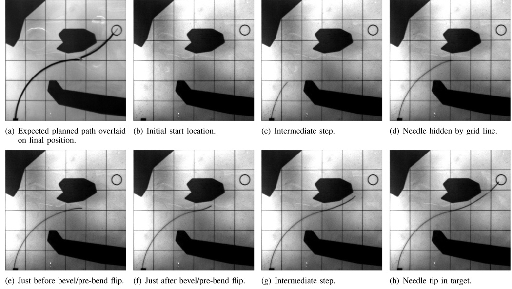
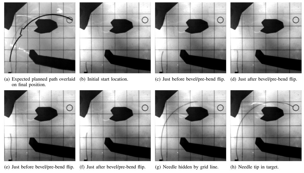
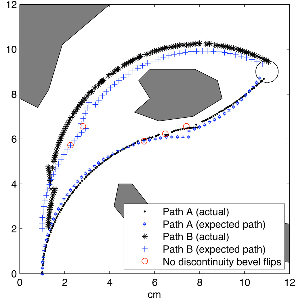
We tested two different start locations, A and B, with the same target and obstacles. Start location A was set to (1 cm, 0 cm). Start location B was set to (1 cm, 2 cm). The trajectory from both start locations is shown in Figures 4 and 5 for one trial each. The needle was able to reach the target while avoiding all obstacles when starting from both start locations. As shown in Figure 4, the needle tip followed the expected planned path closely for path A, and the bevel flipped at nearly the same location as expected in the initial plan.
Fig. 4.
Path A: Needle path when the needle enters at the expected location (1 cm,0 cm). Images are taken from the cameras during the experiments. Each square is 2 cm on each side. The grid lines and obstacles are printed on transparency film and are overlaid on top of the phantom tissue during the experiments.
Fig. 5.
Path B: Needle path when the needle starts at a different location with a position error (1.3 cm,2 cm). Note that the bevel flips direction about 2 cm earlier than initially planned. Images are taken from the cameras during the experiments. Each square is 2 cm on each side. The grid lines and obstacles are printed on transparency film and are overlaid on top of the phantom tissue during the experiments.
In the start location for path B (Figure 5), the expected planned and actual paths were noticeably different. The planner initially calculated the path starting at (1 cm, 2 cm), but the needle actually started 3mm to the right. The planner was given an incorrect initial condition, which is likely to occur in a clinical application. After the first cm, the planner received the estimated state from the imaging system and updated the planned path. The initial discrepancy did not negatively affect the outcome. The planner was able to compute new high-level actions for a new path in real time. The new path changed bevel direction earlier than was expected for plan B. This ability to correct the path in real time highlights the benefit of having closed loop control incorporating both the planner and planar controller. It is interesting to note that the needle was actually moving away from the target for one motion to ensure obstacle avoidance.
We successfully reached the target in three consecutive trials. The path of each insertion is slightly different due to tissue variations, but in each trial, the needle tip reached the target. The location of the bevel flips are not expected to occur at the same location on each trial since different behaviors arise as the noisy camera measurements propagate through the estimator to the planner. The location of the bevel flips varied by 2 cm over these six trials. In one case, the bevel never flipped direction during path B. The planner correctly predicted that the initial trajectory would avoid the obstacles while reaching the target.
In previous experiments, we neglected to account for the discontinuity during a pre-bend flip, which resulted in several failures. After incorporating information about the the pre-bend flip discontinuity, we experienced no failures. Figure 6 shows the expected needle tip paths when the discontinuity is accounted for and shows where the planner would have changed direction without accounting for a discontinuity. Path B is not drastically affected since the bevel flip occurs far from an obstacle. In path A, however, the third bevel flip is likely to cause the tip to translate into the obstacle. In fact, this was a common failure mode prior to accounting for the discontinuity in the path planner.
Fig. 6.
Both paths compared to the actual needle insertion. Both paths successfully reached the target, even path B, which started in a different location than the planner was initially given.
Occasionally during the insertions, one of the cameras would lose tracking of the needle tip; this happened when the needle blended in with the grid lines overlaid on the phantom tissue. Figures 4d and 5g show the needle tip hidden behind a grid line. Figure 6 shows holes in the needle tip trajectory calculated from the imaging system. Regardless of the loss of data, the system was able to continue along the path to the target. It may be possible to use information from the camera that is tracking to reduce the noise by using a triangulating observer. Instead of triangulating directly on the points from two cameras, Rizzi et al. [17] developed a method that estimates Cartesian states based on measurement errors from stereo image planes; even when one camera cannot find the tracked object, their estimator uses the information from the remaining camera to continue estimating. We anticipate that their observer could be adapted for the present context.
V. CONCLUSIONS AND FUTURE WORK
This paper demonstrates a needle steering system that incorporates real-time motion planing, torsion compensation, and image-based control to reach a target while avoiding obstacles in 2D. The optimal planner and planar controller are both based on a modified nonholonomic kinematic model of a needle as it is inserted into tissue. Successful implementation requires compensating for discontinuities in the tip location that occur upon 180° flips of a pre-bent needle.
The use of a pre-bent needle will likely cause damage to the tissue, particularly during needle rotation. One method of reducing the additional trauma is to insert the needle while rotating. Such simultaneous motions will complicate path planning, especially in 3D paths, since the height of the pre-bent needle tip will change following each bevel flip.
The system presented here demonstrates planning and control, each operating over independent degrees of freedom. Of the 6 DOFs, the planner is responsible for three: x, y, and yaw. The planner commands the bevel direction, which is a high level abstraction of the needle roll. The planar controller is responsible for maintaining needle height (near the desired plane) by controlling the remaining three DOFs (z, roll, and pitch). The interaction occurs through the bevel direction. Separating the system this way allows each component to be optimized independently, which greatly reduces system design complexity.
Many of the parameters used in our steerable needle system are experimentally derived. The authors are not aware of any mechanics-based models that predict these parameters, and this is a current area of work for our collaborative team. In a surgical or interventional radiology system, multiple insertions to determine the curvature of the needle path or discontinuities due to a pre-bent needle will not be feasible. We believe that fundamental models based on tissue and needle properties and geometry are important to the design and implementation of clinical needle steering systems.
Determining accurate estimates about the uncertainty in the needle motions will allow more precise control of the needle trajectory. Park et al. [8] developed a method for finding the probability density function of needle insertions. This may be used to more accurately predict the uncertainties in the needle path, which may further improve the performance of the planner.
Acknowledgments
This work is supported in part by the National Institutes of Health under Grants R21-EB003452, R01-EB006435, and F32-CA124138.
Footnotes
REFERENCES
- 1.Webster RJ, III, Kim JS, Cowan NJ, Chirikjian GS, Okamura AM. Nonholonomic modeling of needle steering. Int. J. Robot. Res. 2006;vol. 25(no. 5–6):509–525. [Google Scholar]
- 2.Romano JM, Webster RJ, III, Okamura AM. Teleoperation of steerable needles. Proc. IEEE Int. Conf. Robot. Autom. (ICRA); 2007. Apr, pp. 934–939. [Google Scholar]
- 3.DiMaio S, Salcudean S. Needle insertion modeling and simulation. IEEE Trans. Robot. Autom. 2003;vol. 19:864–875. [Google Scholar]
- 4.Glozman D, Shoham M. Flexible needle steering and optimal trajectory planning for percutaneous therapies. Proc. Med. Image Computing and Computer-Assisted Intervention. 2004:137–144. [Google Scholar]
- 5.Okazawa S, Ebrahimi R, Chuang J, Salcudean SE, Rohling R. Hand-held steerable needle device. IEEE/ASME Trans. Mech. 2005;vol. 10(no. 3):285–296. [Google Scholar]
- 6.Engh J, Podnar G, Kondziolka D, Riviere C. Toward effective needle steering in brain tissue. Conf. of the IEEE EMBS; 2006. pp. 559–562. [DOI] [PubMed] [Google Scholar]
- 7.Abolhassani N, Patel R, Moallem M. Needle insertion into soft tissue: A survey. Med. Engineering and Physics. 2007;vol. 29:413–431. doi: 10.1016/j.medengphy.2006.07.003. [DOI] [PubMed] [Google Scholar]
- 8.Park W, Kim JS, Zhou Y, Cowan NJ, Okamura A, Chirikjian GS. Diffusion-based motion planning for a nonholonomic flexible needle model. Proc. IEEE Int. Conf. Robot. Autom. (ICRA); 2005. Apr, pp. 4600–4605. [Google Scholar]
- 9.Zhou Y, Chirikjian GS. Planning for noise-induced trajectory bias in nonholonomic robots with uncertainty. Proc. IEEE Int. Conf. Robot. Autom. (ICRA); 2004. May, pp. 4596–4601. [Google Scholar]
- 10.Zhou Y, Chirikjian GS. Probabilistic models of dead-reckoning error in nonholonomic mobile robots. Proc. IEEE Int. Conf. Robot. Autom. (ICRA); 2003. Sept., pp. 1594–1599. [Google Scholar]
- 11.Alterovitz R, Lim A, Goldberg K, Chirikjian GS, Okamura AM. Steering flexible needles under markov motion uncertainty. Proc. IEEE/RSJ Int. Conf. Intell. Robots Syst.; 2005. pp. 120–125. [Google Scholar]
- 12.Alterovitz R, Siméon T, Goldberg K. The stochastic motion roadmap: A sampling framework for planning with Markov motion uncertainty. Proc. Robotics: Science and Systems. 2007 [Google Scholar]
- 13.Kallem V, Cowan NJ. Image-guided control of flexible bevel-tip needles. Proc. IEEE Int. Conf. Robot. Autom. (ICRA); Rome, Italy. 2007. Apr, pp. 3015–3020. [DOI] [PMC free article] [PubMed] [Google Scholar]
- 14.Kallem V, Cowan NJ. Image guidance of flexible bevel-tip needles. IEEE Trans. Robot. doi: 10.1109/TRO.2008.2010357. accepted. [DOI] [PMC free article] [PubMed] [Google Scholar]
- 15.Reed KB. Compensating for torsion windup in steerable needles. Proc. IEEE Conf. Biorob; Scottsdale, USA. 2008. [DOI] [PMC free article] [PubMed] [Google Scholar]
- 16.Webster RJ, III, Memisevic J, Okamura AM. Design considerations for robotic needle steering. Proc. IEEE Int. Conf. Robot. Autom. (ICRA); Barcelona, Spain. 2005. pp. 3588–3594. [Google Scholar]
- 17.Rizzi AA, Koditschek DE. An active visual estimator for dextrous manipulation. IEEE Trans. Robot. Autom. 1996;vol. 12(no. 5):697–713. [Google Scholar]


