Abstract
Long, flexible, bevel-tip needles curve during insertion into tissue, and rotations of the needle base reorient the tip to steer subsequent insertions. Friction between the tissue and the needle shaft, however, can cause a severe discrepancy between the needle base and tip angles. In this paper, I demonstrate an algorithm to properly align the entire length of the needle using torque measured at the base. My algorithm uses several intermediate base rotations to align the orientation of points along the shaft with the desired angle, with minimal remaining torque exerted by the base. I performed an experimental validation with four angle sensors attached to the needle throughout the tissue. My compensation algorithm decreased the lag throughout the needle by up to 88%.
I. Introduction
Controlling a maneuverable needle operating under image guidance allows the needle to avoid obstacles, correct position errors at the tip during biopsies, and deliver multiple seeds during a brachytherapy insertion. Accurate needle tip placement is essential during these and other needle-based procedures [1], [2].
One method of steering a needle in tissue involves harnessing the asymmetry of the bevel tip. As a bevel-tip needle is inserted into tissue, asymmetric reaction forces exerted by the tissue cause the needle tip to follow a nearly circular arc of constant curvature [3]. The direction of curvature is controlled by rotating the base of the needle. This method likely adds little to no tissue trauma (over standard straight needles inserted a similar distance) since the insertion and rotation are controlled from outside the tissue. See [4] for a survey that includes needle steering in soft tissue.
During a rotation, torsional friction between the tissue and the inserted length of the needle can result in discrepancies between the angles at the base and bevel-tip of the needle. Previous experiments have demonstrated that the lag can be more than 40° when inserted only 10 cm into a phantom tissue [5]. Any inconsistency in the needle angles is likely to result in poor performance or failure of controllers and path planners.
There are several available methods that have been used to compensate for nonlinear stiction outside the realm of needle steering. Dithering, or adding a high frequency periodic signal, keeps the controlled surface moving and thus prevents the controlled surface from encountering stiction [14]. High frequency motions are likely unsuitable for needle steering due to the possible additional trauma associated with these vibrations.
If the needle tip orientation could be measured directly, a feedback controller could be designed to drive the needle tip orientation to a desired value. Unfortunately, directly measuring the angle of the needle shaft is currently not possible from external imaging. The needles used in clinical procedures are on the order of 1 mm. Smaller needles allow smaller radii of curvature, but further complicate needle tip angle estimation. Current medical imaging has a resolution of approximately 0.8 mm [13], which is adequate for tracking a needle, but is unable to directly measure the bevel angle (much less the angle of the entire shaft). Six DOF magnetic trackers are available, but none are small enough for use at the tip of a steerable needle. Using real-time positions of a needle measured from imaging, Kallem and Cowan [8] are able to recover the roll and pitch of the needle, but their model assumes no torsional friction and, thus, no lag between the base and tip.
Several studies have examined friction forces for inserting a needle into tissue [6], [7], but few have examined the torsional effects of friction. Previous work suggests that torsion along the needle–tissue interface can cause difficulties for bevel-tip needle steering [8], [9], [10], [11], [12]. Abolhassani et al. [12] describe a method to adjust the needle angle based on the measured “twisting” torque assuming all torsional friction occurs at the tip of the needle, an effective approach in their case because the needle was inserted only a short distance when it was rotated. Here, I build on their work in the case that torsional friction is assumed to be continuous along the tissue, a more appropriate assumption for needles inserted to greater depth.
Rather than estimate the bevel angle, the purpose of this paper is to provide an algorithm that “resets” the needle shaft orientation (including the bevel tip) to a known, desired state. In the remainder of this paper, I discuss the motion of a needle rotated in tissue and show a method using stiction torques to put the needle in a state such that further insertion yields predictable results.
II. Methods
A. Device Setup
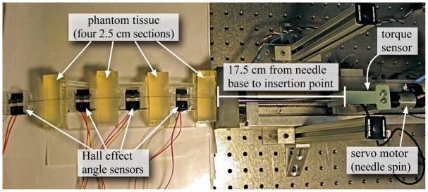
I used the setup shown in Figure 1 for my measurements and experimental validation. The device is capable of inserting and rotating a needle into phantom tissues. A three-axis sensor measures forces and torques at the base of the needle.
Fig. 1.
Experimental setup shown with four sensors interwoven with four equal sections of tissue.
For all experiments presented here, I used a solid 0.39 mm diameter nitinol wire from Nitinol Devices and Components, Fremont, CA. The tissue was a plastisol (M-F Manufacturing Co., Inc.) fabricated using plastic and softener in a ratio of 4:1. I instrumented the needle with hall effect sensors (Honeywell Sensing and Control, Golden Valley, MN, USA) to measure the angle of the needle at multiple locations. For each angle sensor, set screws rigidly attached two magnets to opposite sides of the needle and a platform maintained the magnets at a specific location relative to the hall effect sensor, which measured the angle of the needle.
B. Torsion Models
There are no direct methods to measure the angle at the tip of the needle inside tissue, but a torque sensor can provide useful information about the state of the needle. At specific instances, the torque measured at the needle base will directly relate to the lag.
1) Tip Lag from Torque Measurement
For this analysis, I assume that the friction and material properties are homogeneous throughout and the tissue is rigid. As I will demonstrate later, the rigid tissue assumption will require a slight modification for elastic materials. This analysis also assumes the needle is at steady state when the torque is measured. Steady state can occur in two ways: one, the entire needle is at rest, so static friction is the only active force and two, when the entire needle is rotating at a constant velocity, so damping is the only active force from the tissue. In all cases, I neglect inertial effects.
Using the torque and material properties of the needle, mechanics principles give the relative angle between two points on a solid cylinder (needle) as:
| (1) |
where θ is the angle change over the length (L), τi(x) is the internal torque, which describes the amount of torque propagated along the length of the needle, J(x) is the needle’s polar moment of inertia, G(x) is the shear modulus of the needle, and x is the distance along the needle as defined in Figure 2. The needle has a constant cross sectional area and material properties, so J(x) = J and G(x) = G. Measurements determined that G = 27.2 GPa and J = 2.3 × 10⁻³ mm4 for the nitinol needle used here.
Fig. 2.
The base of the needle contains a motor that can apply a torque. The tissue can apply a torque to the inserted portion of the needle.
When the needle is rotated inside the tissue, friction from the tissue will exert a torque on the needle. At steady state, there is a maximum torque the tissue can exert on the needle due to stiction or damping. I define υ to be the frictional torque per length. The total frictional torque increases linearly with insertion distance, just as frictional insertion force does [7], so the maximum steady state torque the tissue can exert on the needle is υ(lout − lin). If the external torque exerted by the base is less than this maximum torque, the needle tip will not move, but some fraction of the needle will rotate. I define interaction distance, di, as the distance along the needle that has rotated. The interaction distance is such that:
| (2) |
where τb is the torque measured at the base, lin is the distance from the needle base to the insertion point, and lout is the distance from the needle base to the point where the needle exits the tissue, as defined in Figure 2.
The torque exerted by the tissue will cause the internal torque in the needle to decrease linearly from τb to zero as shown in (3).
| (3) |
where xt is the distance along the needle measured from the insertion point as shown in Figure 2.
Substituting (3) into (1) and integrating over the length of the needle that rotated inside the tissue (lin to di) yields
| (4) |
Equation (4) shows how the angle will change throughout the rotated portion of the needle inside the tissue given the torque measured at the base. Note that this says nothing about the remaining unrotated portion of the needle. If the needle tip has been rotated, then di = lout − lin. Setting xt = di shows the lag of the needle tip relative to the insertion point. Equation (5) shows the lag associated with the measured torque when the needle tip has also rotated.
| (5) |
Outside the tissue, there are no frictional forces, so the internal torque is constant, thus integrating (1) from zero to lin results in a lag of
| (6) |
The lag inside and outside the tissue will add due to the principle of superposition and θout = θtip, so the total lag from the base to the tip is
| (7) |
Equation (7) is only valid for rotations large enough that cause the tip angle to also rotate. If this condition is not satisfied, the measured torque will report incorrect lag angles.
Under these assumptions, using (7) will improve the accuracy of the lag estimate proposed by Abolhassani et al. [12] by 22% for a 27.5 cm needle inserted 10 cm into a tissue (same length needle shown in Figure 3).
Fig. 3.
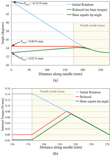
Finite element simulation results showing (a) the angle along the needle and (b) the internal torque for three scenarios: (1) the base was rotated to 45° and held (initial rotation), (2) the base was rotated to 45° and then moved such that the torque was zero (relaxed), and (3) the base was rotated to 45° and then rotated to the same angle as the tip (base equals tip angle). The torque measured at the base only relates to the torsion lag after the initial rotation.
2) Finite Element Model
In order to better understand how multiple small rotations affect the angle along the needle shaft, I implemented a finite element (FE) model of the needle as it is rotated inside tissue. The model uses (6) to connect each node. The interaction between each needle node and the tissue is modeled as Karnopp friction, which is composed of a constant static friction within a small velocity near zero and damping elsewhere, as was done in [7] for needle insertion forces. The material properties are modeled after those used in the experimental validation and discussed in section II-B.3. The tissue is assumed to be completely rigid, so there are some corresponding limitations in the accuracy of my simulation.
The FE model was constructed of 199 disk elements inside the tissue, each of length 0.5 mm, and one element of length 175 mm outside the tissue. The element outside the tissue was simply treated as a long torsional member since no external forces acted along it’s length. The simulation was run with a time step of 10−6 s.
3) Material Characteristics
Three parameters are required for the needle. J is defined as J = πd4/32, so J = 2.3×10⁻³ mm4. G was determined by rigidly fixing the needle tip at a fixed angle while rotating the needle base. The remainder of the needle was unrestrained. A 90° rotation of the 41 cm needle resulted in a torque of 0.24 N-mm. Using (6) shows that G is 27.2 GPa. The finite element analysis also requires the density of the needle, which is 6.45 g/cm3.
I experimentally determined the stiction force and damping required by the Karnopp friction model. During steady state needle rotation, I assumed all applied torque from the tissue is from damping, so I can use τb = bθ̇ to estimate the damping coefficient, b. I rotated the base at θ̇ = 0.08 rad/sec and found that b = 2.8 N-mm-s for a 100 mm insertion. To measure the stiction forces, I measured the base torque after the needle was rotated and reached motionless steady state and found that static friction is 0.45 N-mm for a 100 mm insertion. Both the damping and static friction will increase linearly with insertion distance.
C. Controlling the Needle Tip
Compensating for torsional friction by rotating an amount equal to that predicted by (7) is not enough to put the needle in a suitable state to prevent errors in the tip angle. Even if the needle tip is at the correct location, any insertion force will break stiction and reduce the friction, which will cause the tip angle to rotate to an unknown angle. Also, it is possible to have the tip and base both be at the desired angle while the rest of the points along needle are at different angles.
Figure 3 shows my finite element simulation of the needle during three rotations. Initially, the entire needle was at 0° (not shown). The base was rotated to 45° and the tip only rotated to 33° due to torsional friction. In this state, the torque measured at the base (−0.14 N-mm) is directly related to the lag since all torque from the tissue is in the same direction (i.e. no torsion windup) as shown in Figure 3b. In this state, (5) accurately describes the resulting tip lag. When the needle base is moved such that there is no measured torque at the base, there was still a 1.5° lag. In this state, the measured torque does not directly relate to the lag since there is significant torsion applied in both directions from the tissue. Notice the sharp change in direction in the internal torque near the midpoint of the tissue. When the needle base is rotated to the same angle as the tip, the measured torque was actually positive. The frictional torques from the tissue and a small torque from the base are holding the needle in place, even though the tip and base angles are equal. When the needle is in a non-ideal state, such as just described, the measured torque at the base can be misleading.
Ideally, it would be possible to place the entire needle shaft at a constant angle, but this would take a large number of rotations to accomplish. Apart from a constant angle throughout, I propose that a reasonable state for the needle consists of the three following conditions:
| (8a) |
| (8b) |
| (8c) |
This proposed state of the needle does not eliminate torsion windup since some residual, but small torques and angle changes will remain along the inserted portion of the needle. The sum of the absolute value of the torque may be high, but an integral equal to zero implies that any reduction of friction could allow the needle and tissue to internally balance the torques without exerting a torque on the needle base or rotating the needle tip. The angles for the base and tip need to be the same as the desired angle so that no additional torques will develop. Similarly, no torque should exist at the needle base, otherwise the needle is likely to rotate when the stiction is broken during an insertion.
My method to put the needle in a suitable state involves rotating the needle multiple times by specific amounts. This method can be visualized more easily by imagining a translational version represented by an untethered rope laying on the ground. The rope can be put in a nearly straight line by slowly wiggling the rope back and forth while decreasing the amplitude of each wiggle. Each wiggle actually places a portion of the rope in a curved path, but wiggling enough times approximates a line.
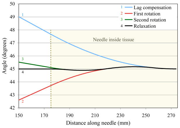
I used the FE simulation to generate an ideal summary of my algorithm, which is shown in Figure 4. First, the needle base is rotated to θdesired (45° in this example), which should be greater than υ(lout−lin)2/(JG). Then, the torque is measured and the lag, θlag, is determined. The needle is controlled to θdesired + θlag. This lag compensation will place the needle tip at θdesired. Next, the needle base is rotated to θdesired −0.75θlag and then to θdesired + 0.25θlag. These two rotations rotate the center portion of the needle slightly above and below the desired angle. The final rotation is actually the needle base rotating to the point where no base torque exists, which is θdesired.
Fig. 4.
Finite element simulation of my algorithm to put the needle in a reasonable state. The needle base was initially rotated so the tip would be at 45°. The next three rotations position the needle with minimal amount of torque along the length of the needle with no torque measured at the base.
Rotating by 0.75θlag and 0.25θlag causes the interaction distance to be 0.75(lout − lin) and 0.25(lout − lin), respectively. These rotations cause the tissue between 0.25(lout − lin) and 0.75(lout − lin) to exert a positive torque on the needle while the remaining tissue exerts a negative torque on the needle. The torque along the entire needle will integrate to zero. These proportions are not the only values that satisfy my metric defined in (8), but it does involve the least number of rotations. Additional rotations will reduce the largest angle, but will take additional time.
III. Results and Discussion
As stated above, it is not possible to measure the angle of the needle inside tissue, so I cut the tissue and measured the angle at three discrete locations to validate the model. The needle enters four sections of tissue separated by three angle sensors as drawn in Figure 5. The angles for the test setup are predicted by combining (5) and (6). The principle of superposition states that the angles add linearly, so the angle of the needle tip after a rotation for the experimental setup is predicted by
Fig. 5.
Experimental setup to measure the angles at multiple locations along the inserted portion of the needle.
| (9) |
Notice that the lag associated with the tissue is the same as it would be if there were no sensors. The internal torque does not change during the sensor regions, but the torque through the sensor regions causes an extra angle change. The internal torque is zero for the fourth sensor, so there are only three sensor regions that contribute an extra lag.
During my experiments, I used an over damped PID controller to move the needle base and waited 3.0 seconds before measuring the angles to allow any damping effects to settle. The PID controller was tuned to reach zero steady state error with no overshoot.
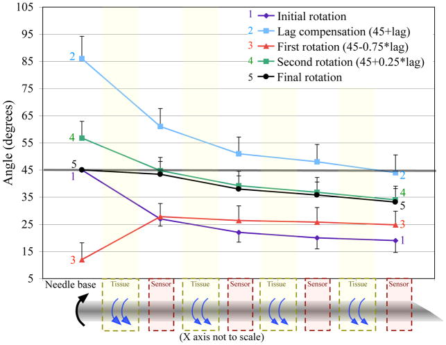
For each experiment, the entire needle starts at zero degrees and the desired angle is 45°. Figure 6 shows the angles at each angle sensor during my algorithm for an average of five separate trials. The first motion moves the base to 45° while the tip is lagging by 26°. The torque is measured and the base is moved by the amount predicted by (9). The next two motions follow the algorithm. The final motion puts the base at the desired angle, but the tip angle is still lagging by 12°. The lag is improved, but the needle is not at the ideal state.
Fig. 6.
Results from my algorithm performed on a phantom tissue, without compensating for elastic deformation of the tissue. We decreased the tip lag by 54%. The error bars represent the standard deviation over 5 trials. (Half bars used to prevent overlap and increase clarity.)
The remaining lag at the conclusion of the rotations is likely due to elastic effects in the tissue, which were not modeled. The tissue elasticity will allow the needle to rotate even when stiction has not been broken. When the needle base is returning to a certain angle, the tissue elasticity will initially allow the needle to move without any additional forces; thus the needle will rotate further than expected, which likely accounts for the discrepancy in Figure 6.
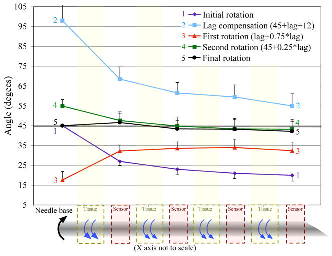
To test my hypothesis that the tissue elasticity is causing the remaining lag, I implemented the same algorithm, but compensated for the elasticity in the first motion. Instead of only rotating by the amount predicted by (9), I rotated the base by an additional 12°, which is the remaining lag likely due to elasticity. Figure 7 shows the results of my algorithm modified to compensate for the tissue elasticity. Only the first motion is needed to overcompensate the elasticity. The last three motions were performed exactly like the original algorithm. At the end of these rotations, the final angle of the needle only lagged by 3° and the angles along the needle were all within 3° of θdesired.
Fig. 7.
Results from my algorithm modified to account for elastic tissue. I decreased the tip lag by 88%. The error bars represent the standard deviation over 5 trials. (Half bars used to prevent overlap and increase clarity.)
The final state of the needle is close to my proposed state. Equation (8a) states that the torque exerted along the needle should integrate to zero. Measuring the torques along the needle is difficult, but the measured angle provides a reasonable approximation. The average angle along the needle shown in Figure 7 is 43.8°. The difference between the maximum and minimum angles is 4.4°, which indicates that there is minimal angle change and internal torque along the needle. Equation (8b) states that the measured torque should be zero after the final rotation. The torque at the final state was 0.068 N-mm, which was significantly less than the torque without accounting for tissue elasticity, but was still larger than zero. The standard deviation of the repeated trials was around ±5° for each of the measured angles, so having a small remaining torque and an error of ≤ 5° is acceptable and significantly better than the state of the needle after the initial rotation.
IV. Conclusions and Future Work
The needle system described in this paper is essentially a one input, continuous output system since I am not changing the insertion depth. The input is position of the needle base and the output is the angle along the needle. Multiple rotations of the needle base cause a windup where the angle and internal torque can vary along the length of the needle. Most severely, torsional friction along the needle-tissue interface causes the needle tip to lag the controlled location at the needle base.
Torsional lag is a very detrimental issue for controllers and path planners operating on a steerable needle. If the lag is not compensated for, the bevel will not be aligned with the base and insertion will cause the needle to advance in an unknown direction. My proposed metric defines a reasonable and achievable state that is suitable for further rotation or insertion into the tissue. In this paper, I demonstrate one method to compensate for the torsion windup using measurements from a torque sensor. This method involves multiple rotations to place the entire needle near the desired angle.
I show that compensating for tissue lag by multiple rotations can reduce the torsional lag by 88%. My experiments also show that tissue elasticity further complicates torsion windup by allowing some needle rotation without the needle slipping relative to the tissue. My algorithm, combined with an extra rotation to account for the tissue elasticity, allows the entire needle to achieve the desired angle with minimal residual error. Future models will extend the torsion measurements to account for the elasticity in the tissue. Similarly, the future finite element simulation will incorporate tissue effects using the Kelvin–Voight or Maxwell tissue model.
Acknowledgments
This work was supported by NIH grant R01 EB006435.
The author thanks Noah Cowan and Allison Okamura for critically evaluating the manuscript. The author also thanks John Swenson, Vinutha Kallem, and Tom Wedlick for help with the needle steering device.
References
- 1.Nath S, Chen Z, Yue N, Trumpore S, Peschel R. Dosimetric effects of needle divergence in prostate seed implant using I and Pd radioactive seeds. Medical Physics. 2000 May;27:1058–1066. doi: 10.1118/1.598971. [DOI] [PubMed] [Google Scholar]
- 2.Youk JH, Kim EK, Kim MJ, Lee JY, Oh KK. Missed breast cancers at US-guided core needle biopsy: How to reduce them. Radiographics. 2007 doi: 10.1148/rg.271065029. [DOI] [PubMed] [Google Scholar]
- 3.Webster RJ, III, Kim JS, Cowan NJ, Chirikjian GS, Okamura AM. Nonholonomic modeling of needle steering. The International Journal of Robotics Research. 2006;25(5–6):509–525. [Google Scholar]
- 4.Abolhassani N, Patel R, Moallem M. Needle insertion into soft tissue: A survey. Medical Engineering and Physics. 2007;29:413–431. doi: 10.1016/j.medengphy.2006.07.003. [DOI] [PubMed] [Google Scholar]
- 5.Reed KB, Cowan NJ, Okamura AM. Torsion windup in steerable needles. Proc Medical Image Computing and Computer-Assisted Intervention (MICCAI) 2008 submitted. [Google Scholar]
- 6.Kataoka H, Washio T, Chinzei K, Mizuhara K, Simone C, Okamura AM. Measurement of the tip and friction force acting on a needle during penetration. Proc Medical Image Computing and Computer Assisted Intervention (MICCAI) 2002:216–223. [Google Scholar]
- 7.Okamura AM, Simone C, O’Leary MD. Force modeling for needle insertion into soft tissue. IEEE Trans Biomedical Engineering. 2004;110(51):1707–1716. doi: 10.1109/TBME.2004.831542. [DOI] [PubMed] [Google Scholar]
- 8.Kallem V, Cowan NJ. Image-guided control of flexible bevel-tip needles. IEEE International Conference on Robotics and Automation (ICRA); Rome, Italy. 2007. [DOI] [PMC free article] [PubMed] [Google Scholar]
- 9.Alterovitz R, Lim A, Goldberg K, Chirikjian GS, Okamura AM. Steering flexible needles under markov motion uncertainty. International Conference on Intelligent Robots and Systems (IROS); 2005. pp. 120–125. [Google Scholar]
- 10.Webster RJ, III, Memisevic J, Okamura AM. Design considerations for robotic needle steering. IEEE International Conference on Robotics and Automation (ICRA); Barcelona, Spain. 2005. pp. 3588–3594. [Google Scholar]
- 11.Kallem V, Chang DE, Cowan NJ. Task-induced symmetry and reduction in kinematic systems with application to needle steering. IEEE/RSJ Intelligent Robots and Systems (IROS); San Diego, USA. 2007. [DOI] [PMC free article] [PubMed] [Google Scholar]
- 12.Abolhassani N, Patel RV, Ayazi F. Minimization of needle deflection in robot-assisted percutaneous therapy. The International Journal Of Medical Robotics And Computer Assisted Surgery. 2007;3:140–148. doi: 10.1002/rcs.136. [DOI] [PubMed] [Google Scholar]
- 13.Ding M, Cardinal H. Automatic needle segmentation in three-dimensional ultrasound image using two orthogonal two-dimensional image projections. Medical Physics. 2003;30(2):222–234. doi: 10.1118/1.1538231. [DOI] [PubMed] [Google Scholar]
- 14.Olsson H, Åström K, Canudas De Wit C, Gäfvert M, Lichinsky P. Friction models and friction compensation. European Journal of Control. 1998;4(3):176–195. [Google Scholar]


