Abstract
This article presents recent results in the development of the skin and bone integrated pylon (SBIP) intended for direct skeletal attachment of limb prostheses. In our previous studies of the porous SBIP-1 and SBIP-2 prototypes, the bond site between the porous pylons and residuum bone and skin did not show the inflammation characteristically observed when solid pylons are used. At the same time, porosity diminished the strength of the pylon. To find a reasonable balance between the biological conductivity and the strength of the porous pylon, we developed a mathematical model of the composite permeable structure. A novel manufacturing process was implemented, and the new SBIP-3 prototype was tested mechanically. The minimal strength requirements established earlier for the SBIP were exceeded threefold. The first histopathological analysis of skin, bone, and the implanted SBIP-2 pylons was conducted on two rats and one cat. The histopathological analysis provided new evidence of inflammation-free, deep ingrowth of skin and bone cells throughout the SBIP structure.
Keywords: arthroplasty, bone, direct skeletal attachment, infection, limb amputation, osseointegration, porous pylon, prosthetic rehabilitation, skin, skin and bone integrated pylon
INTRODUCTION
Dr. Per-Ingvar Brånemark introduced the method of direct skeletal attachment of limb prostheses in the 1980s [1]. The method holds advantages over the prior art but has concerns associated with it as well, especially related to inflammation in the skin surrounding the implant. Extensive multidisciplinary studies have been conducted in different countries to improve the safety and longevity of the technology [2]. In 2004, a study was initiated to develop a totally porous pylon for direct skeletal attachment of limb prostheses [3]. Under the assumption that a porous structure can be manufactured with sufficient strength [4], von Recum suggested that porosity could increase the pylon’s resistance to detachment (avulsion) from surrounding tissues [5], because of the bonding of the cells outside the pylon with the cells inside the pylon. Therefore, the pylon was made porous along the entire longitudinal axis to avoid the negative consequences of skin repositioning seen in the prior art.
The natural bond created through a pore in the wall of the pylon between the cells outside and inside the pylon has been demonstrated to produce an additional “cell-to-cell” attachment (adhesion) force that increases cells’ resistance to detachment from the pylon [6]. The yearly outcomes of the study are presented in the Table for 2004 through 2006, published elsewhere [3–4,6–10], and presented in this article for 2007 and 2008.
Table.
Outcomes of 2004–2008 studies on skin and bone integrated pylon (SBIP).
| Study Component | 2004 | 2005 | 2006 | 2007 | 2008 |
|---|---|---|---|---|---|
| SBIP Design, Manufacturing | Totally porous tablets [1]. | SBIP-1 developed; totally porous [2]. | SBIP-2 developed porous-composite [3]. | Porous-composite prototypes. | SBIP-3 developed. |
| Strength Tests | — | 20 MPa | 70 MPa | 177 MPa [3] | 480 MPa |
| Fatigue Tests | — | — | — | — | 5,000,000 cycles |
| Tests In Vitro | Spreading and growth of human dermal fibroblasts on tablets treated with collagen and histone [4–5]. | — | — | — | |
| Tests In Vivo | Study on 4 rats with tablets implanted through skin [6]. No inflammation. Signs of ingrowth. | Study on 7 rats with SBIP-1 [3]. Penetration of surrounding skin cells. | Study on 30 rats with SBIP-2 [7]. No inflammation. Deep penetration of skin cells inside the pylon. | Study on 2 rats and 1 cat. Histopathological analysis showed ingrowth of skin and bone through-out entire volume of the implant with no signs of inflammation [8]. | |
Pitkin M, Blinova MI, Yudintseva NV, Potokin IL, Raykhtsaum G, Pinaev GP. Skin and bone integrated prosthetic technology. I. Characterization and morphology of human cells cultivated on titanium implants of different structures [abstract]. In: Proceedings of the 9th Russian National Congress, People and Health. 2004 Nov 22–26; St. Petersburg, Russia; St. Petersburg: Russian National Congress; 2004. p. 217.
Pitkin M, Raykhtsaum G, inventors. Skin integrated device. United States patent US 20070071788. 2007 Mar 29.
Pitkin M, Raykhtsaum G, Galibin OV, Protasov MV, Chihovskaya JV, Belyaeva IG. Skin and bone integrated prosthetic pylon: A pilot animal study. J Rehabil Res Dev. 2006;43(4):573–80. [PMID: 17123195]
DOI:10.1682/JRRD.2005.05.0160
Blinova MI, Yudintseva NV, Kuhareva LV, Goryuhina OA, Potokin IL, Pinaev GP, Pitkin M. Skin and bone integrated prosthetic technology. II. Morphology and growth of cells on implants treated with different proteins [abstract]. In: Proceedings of the 9th Russian National Congress, People and Health. 2004 Nov 22–26; St. Petersburg, Russia; St. Petersburg: Russian National Congress; 2004. p. 205.
Yudintseva N, Blinova M, Pinaev G, Potokin I, Pitkin M, Raykhtsaum G. Characterization and morphology of cells cultivated on titanium implants of different structures. In: 2nd World Congress on Regenerative Medicine. 2005 May 18–20; Leipzig, Germany. Milan (Italy): International Journal of Artificial Organs; 2005.
Galibin OV, Protasov MV, Chikhovskaya JV, Belyaeva IG, Pitkin M. Skin and bone integrated prosthetic technology. III. An exposed implantation of a porous titanium pellet into the skin [abstract]. In: Proceedings of the 9th Russian National Congress, People and Health. 2004 Nov 22–26; St. Petersburg, Russia; St. Petersburg: Russian National Congress; 2004. p. 210.
Pitkin M, Raykhtsaum G, Pilling J, Galibin OV, Protasov MV, Chihovskaya JV, Belyaeva IG, Blinova MI, Yudintseva NM, Potokin IL, Pinaev GP, Moxson V, Duz V. Porous composite prosthetic pylon for integration with skin and bone. J Rehabil Res Dev. 2007;44(5):723–38. [PMID: 17943684]
DOI:10.1682/JRRD.2006.12.0160
Jacobson S. Summary of histopathologic evaluation of a titanium pylon implanted in a cat for Poly-Orth International, Report VTF00001. Frederick (MD): Charles River Pathology Associates. 2008.
During the current study, we mathematically modeled, manufactured, and mechanically tested the composite skin and bone integrated pylon (SBIP)-3 for resistance to fatigue associated with prosthetic functional tasks. The SBIP-3 retained the characteristics of the SBIP-2 that allow for bone and skin cells to grow inside the pylon.
For the SBIP-2, we conducted the first histopathology analysis in a study with two rats and one cat, which complimented our previous morphological analysis [6]. We concluded that the ingrowth-inviting ability of the pylon was not compromised by the addition of enforcement inserts.
METHODS
Development of Composite Porous Pylon
Modeling Mechanical Properties of SBIP-3 Titanium Composite Implant Structure
We analyzed the mechanical properties of the SBIP-3 prototypes, which have a cross-shaped insert (Figure 1), by using a generalized model of the mechanical properties of composite porous structures [6]. The tensile, ET, and flexural, EF, moduli of a cylindrical rod of radius r, composed of two or more materials with differing elastic moduli, can be expressed as
Figure 1.
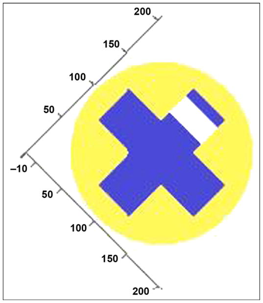
Cross section of cross-shaped insert with single hole drilled through one rib at axis of hole (blue = solid titanium, yellow = porous titanium, white = no material). Numbers represent percentage of radius length.
| (1) |
| (2) |
where z is the vertical displacement from the plane of bending, x is the horizontal displacement from the center-line of the rod, and Ex,z is the elastic modulus of the material at point x,z in the cross section. To find the effective flexural and tensile stiffness of the rod, we only need to define a function (or series of functions) that identifies the elastic modulus of the material at any point in the cross section (see Figure 1 as an example).
The logical geometric function that describes the fractional property multiplier of the material at a point x,z in the cross section of the pylon is given by
| (3) |
where h is the height or width of the cross-shaped insert and 2t is the thickness of the insert. The function (φ) describes how the fractional property being calculated varies with the volume fraction of porosity. Thus, if a point x,z lies outside the cylindrical pylon, the fractional property multiplier is 0; if it lies within the cross-shaped insert, the fractional property multiplier is 1; and if it lies within the porous matrix, the fractional property multiplier is given by the appropriate choice of (φ). For flexural modulus, Φ(φ) = (1 ∠φ)5.5, while for flexural strength, Φ(φ) = (1 ∠φ)3.
The effective tensile and flexural moduli of the rod with a cross-shaped insert is shown in Figure 2 relative to the elastic modulus for a range of orientations of the insert relative to the plane of bending. The moduli are plotted (Figure 2) relative to the modulus of the solid insert material and assuming that the elastic modulus of the porous solid for ETi(φ) is
Figure 2.
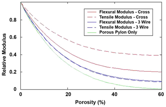
Tensile and flexural moduli of the two reinforcing geometries as function of level of porosity in matrix, together with modulus of porous solid alone. CROSS = cross-shaped insert, 3 WIRE = porous cylinder reinforced with three wires.
| (4) |
where φ is the volume fraction of porosity. The value of the modulus of the porous solid alone is indicated by the dotted line (Figure 3). The effect of the level of porosity of the elastic moduli of the two reinforcing geometries is shown below relative to that of solid titanium (see Figure 2). The strengths of the reinforced porous titanium rods in tension can be estimated as
Figure 3.
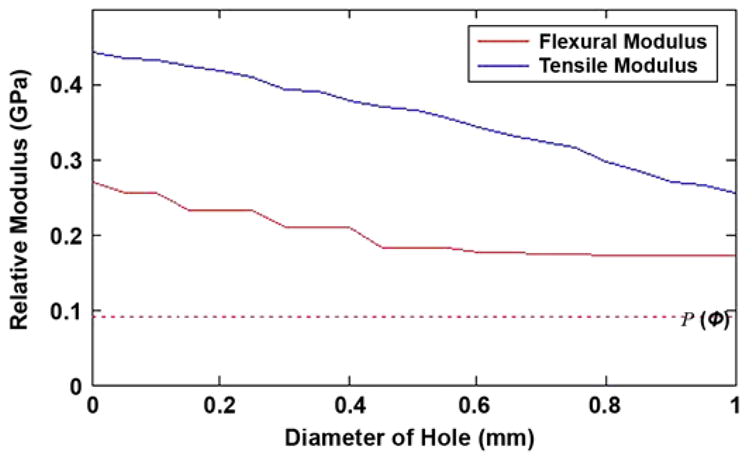
Potential reduction in flexural and tensile moduli from holes of given diameter in web of solid insert. Dotted line indicates relative modulus of pylon, P(φ), consisting solely of porous solid with 35% by volume.
| (5) |
where σx,z is the strength of the material at a point x,z in the cross section and can be calculated from the fractional multiplier f(x,z) in Equation (3) but using σTiΦ(φ). The strength of the porous matrix is given by
| (6) |
To determine the flexural strength of the reinforced porous titanium rod, we need to consider the bending strain at any distance z above and below the plane of zero bending strain. Once the strain at a point x,z exceeds the failure strain of the material at the point, one can assume that the material has failed (weakest link hypothesis). The failure strain of the porous titanium matrix is given by
| (7) |
The flexural strength of a solid rod would simply be the product of the flexural modulus of the rod, EF, and the strain at failure of the solid material, ε. Similarly, the flexural strength of a wholly porous rod would be the product of the flexural modulus of the rod and the strain at failure of the porous solid, ε (φ). Thus by analogy, the composite rod would, if the porous matrix failed first, also be the product of the flexural modulus of the composite rod and the strain at failure of the porous solid; i.e.,
| (8) |
However, even after the porous matrix fractures, the remaining solid insert(s) may continue to support the imposed load. The maximum tensile bending stress occurs at the outer edge of the rod and decreases linearly with distance to the center of the rod because the bending strain decreases linearly over the same distance. The solid titanium insert will fail when
| (9) |
where ε is the imposed bending strain and ru is the maximum radial extent at which the solid insert(s) exists in the cross section. Substituting the Hooke’s law definition of strain,
| (10) |
the composite rod will fail at the lesser of the two stresses indicated above; i.e.,
| (11) |
Thus, the model provides a prediction for strength and flexural modulus for a matrix with different volume percent porosity and different solid insert designs.
Mathematical Modeling of Effect of Total Porosity
Mathematical analysis has been conducted on the effect of holes in the solid core of the pylon’s composite structure on its mechanical characteristics. Figure 1 shows a cross section of the cross-shaped insert with a single hole drilled through one of the ribs of the solid insert. The pylon is 4 mm in diameter with a 3 mm-wide and 1 mm-thick cross-shaped insert.
The graphs in Figure 3 show how the tensile and flexural moduli of the pylon, relative to those of a 100 percent solid titanium pylon (relative modulus = 1), vary as the diameter of the hole is increased from zero to the width of the insert at the point along the axis of the pylon where the hole is of maximum diameter. The volume fraction of porosity in the matrix surrounding the cross-shaped insert is 35 percent, and the modulus of a pylon of this porosity without the cross-shaped insert is shown as the horizontal dotted line in Figure 3, i.e., 9.4 percent of that of solid titanium. A 0.5 mm-diameter hole in one web of the cross-shaped insert would reduce the localized flexural modulus from 27 to 18 percent of that of solid titanium at the maximum diameter of the hole. If the hole diameter, measured along the axis of the pylon, were averaged from its maximum to zero, then the average flexural modulus over the axial extent of the hole would be 21 percent of that of solid titanium.
Holes are introduced into the solid titanium insert to enable ingrowth of tissue while maintaining sufficient tensile and flexural moduli. The maximum benefit would be derived from the holes when they are placed in a spiral pattern so as to avoid holes directly opposite or immediately adjacent to one other. The trends illustrated in Figure 3 indicate the maximum reduction in tensile and flexural stiffness. However, if the pitch of the holes along a given rib is 16× their diameter (i.e., holes on adjacent ribs are spaced at 4×, 8×, and 12× the hole diameter), then the effective reduction in flexural modulus of the insert will be just 8 percent of its value without the holes, reducing the flexural modulus of the pylon to 26 percent of that of solid titanium. Thus with respect to the flexural modulus, the effect of creating a spiral of holes along the length of the insert is minimal. The reduction in tensile modulus is not affected by the spiral spacing of the holes because it scales solely with the cross-sectional area perpendicular to the axis of the pylon; a 0.5 mm-diameter hole would be expected to reduce the tensile modulus of the porous pylon with a solid cross-shaped insert from 44 to 36 percent of that of solid titanium.
Finite Element Analysis
The novel design of SBIP-3 [11] creates certain problems of durability, especially for the side elements (fins) of the cylindrical construct. Practicality of the modeling is necessitated by the high costs associated with manufacturing the samples for mechanical testing.
A three-dimensional (3-D) model of the human femur was created with computed tomography (CT) (Siemens Somatom Emotion™; Berlin-Munich, Germany) in the conventional manner [12]. We generated the cross section of bone for each slice by using CT image data of a cadaver. The model was used as input data for the engineering program SolidWorks 2006 (SolidWorks Corp; Concord, Massachusetts). A bone segment 120 mm in length, 32 mm in outer diameter, and 16 mm in inner diameter was cut out (Figure 4). Bone fragment dimensions were taken to match a study [13] in which a finite element analysis (FEA) model of the bone-fixture interface was developed. A 3-D computer-aided design model of the implantable pylon SBIP-3 with three pairs of side elements (fins) was constructed (Figure 5). The dimensions of the fins, the spaces between them, and the loads were the input parameters for calculations (Figure 6). We assumed full osseointegration of the porous implant with the surrounding bone as in an FEA study on dental implants [14]. The pylon is positioned in such a way that the fins’ plane is parallel to the cross section of the frontal and transversal planes of the body. The implanted portion of the pylon is 60 mm in length, and the portion remaining outside is 30 mm in length (Figure 7).
Figure 4.
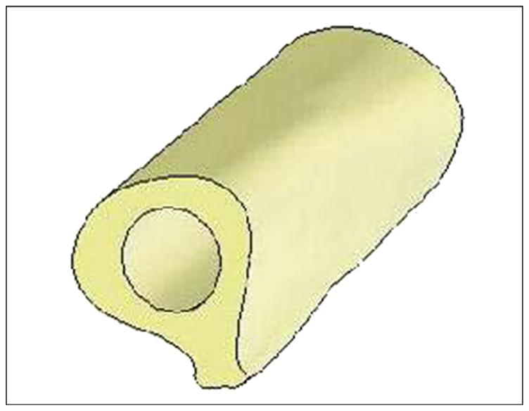
Three-dimensional computer-aided design model of femur bone fragment used in finite element analysis.
Figure 5.
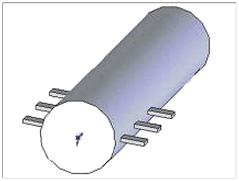
Three-dimensional computer-aided design model of the pylon with three pairs of fins 1 (skin and bone integrated pylon 3).
Figure 6.
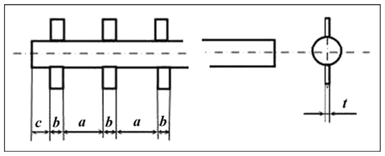
Dimensions a, b, c, and t of fins 1 (skin and bone integrated pylon 3).
Figure 7.
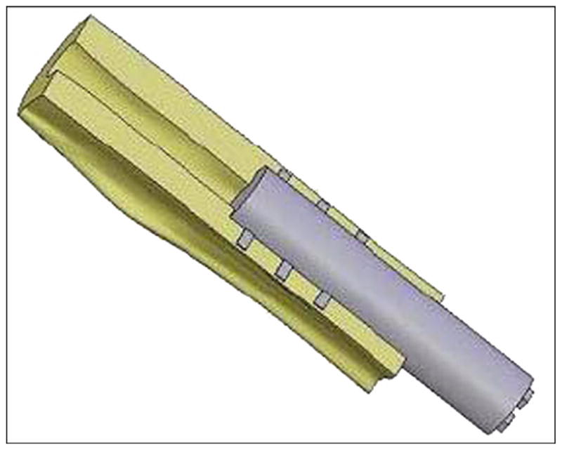
Three-dimensional computer-aided design model of skin and bone integrated pylon 3 implanted in bone fragment.
Material of the compact bone was considered isotropic, with a modulus of normal elasticity of 18 GPa, density of 2,000 kg/m3, ultimate tensile strength of 170 MPa, and Poisson ratio of 0.3 [15–16]. For the porous composite implant, modulus of normal elasticity was 35 GPa, ultimate tensile strength was 410 MPa, density was 4,700 kg/m3, and yield strength was 160 MPa.
We assumed that the proximal end of the bone fragment was fixed. The load conditions were taken from Xu et al. [13]. Compressive load F of 3,750 N was applied to the open outer end of the implant along its longitudinal axis, with a torsional moment L1 of 20 Nm, bending moment L2 of 40 N·m, and transversal moment L2 of 40 N·m (Figure 8).
Figure 8.
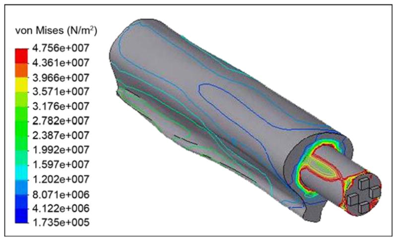
Von Mises stress distributions in bone-pylon system (outer view).
The stress-strain distributions of the “bone-implant” were calculated with COSMOSWorks software (Solid-Works Corp; Concord, Massachusetts). First, we considered the implant as a SBIP-3 pylon with three pairs of fins (see Figure 5). Second, the implant was considered as a regular cylinder. We wanted to learn whether the fins had any effect on the stress-strain distributions.
The von Mises stresses are shown in Figure 9. Thickness of the fins had very little effect on the maximal stresses. However, width of the fins and distance between them provided a more significant effect. In the study by Xu and colleagues [13], the maximal von Mises stresses in the implant were in the distal zone of the femur, with values of 127 and 137 MPa in the 22.0 and 21.5 mm-diameter implants, respectively. Our model showed maximal stress in the distal zone of the 16 mm-diameter implant to be as little as 83.2 MPa (Figure 10).
Figure 9.
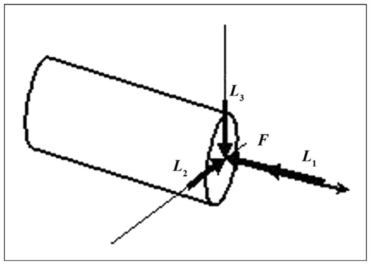
Schematic of application of force (F) and moments (torsional [L1], bending [L2], transversal [L3]) to distal end of pylon.
Figure 10.
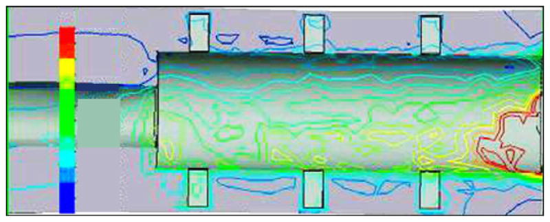
Von Mises stress distributions in bone-pylon system in medial-lateral cross section for skin and bone integrated pylon 3 with fins. See Figure 9 for stress distribution scale.
As far as the proximal zone, our model demonstrated relatively low stresses (see Figure 10) in contrast with the higher stresses in the proximal zone of the SBIP-2 (Figure 11). Similar results were demonstrated in the FEA study by Xu and colleagues [13].
Figure 11.
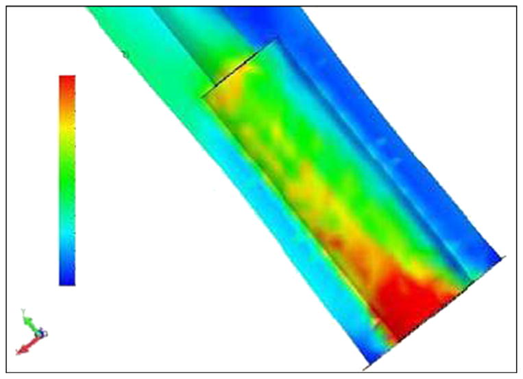
Von Mises stress distributions in bone-pylon system in medial-lateral cross section for cylindrical skin and bone integrated pylon 2. See Figure 9 for stress distribution scale.
The FEA model also showed that the design with fins decreases stresses on the bone in the distal zone of implantation, compared with existing cylindrical fixtures [13] and the cylindrical pylon SBIP-2 (see Figure 11). We suggest that the fins increase the effective area of contact between the bone and pylon in the proximal zone, which decreases stresses in this zone. We further suggest that if the fins are moved closer to the distal zone of the bone, the stresses in that zone could also be decreased.
Manufacturing and Mechanical Testing
A manufacturing process for pylons of cylindrical shape (SBIP-2) and with fins (SBIP-3) was developed. The samples for the study were manufactured by ADMA Products, Inc (Hudson, Ohio). We used commercially pure titanium sponge powders. The powders were filled and compacted inside a graphite mold with 3 mm- and 5 mm-round channels (Figure 12). The walls of the graphite mold channels were sprayed with boron nitride paste before being filled. No pressure was applied during compacting. To achieve uniformity along the length of the channels, we placed the mold on a vibrating table. The experimental samples of SBIP-2 were reinforced with a 0.5 mm-diameter wire. The experimental samples of SBIP-3 were manufactured with 0.5 mm-thick cross-frame inserts made with the titanium alloy Ti6Al4V ELI (Figure 13).
Figure 12.
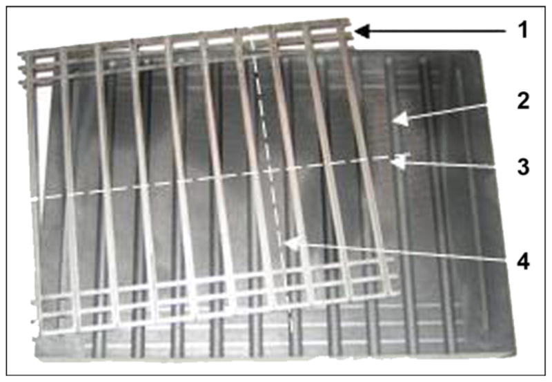
Base of graphite mold (1) and frame assembly of 10 double inserts (2). After sintering, skin and bone integrated pylon 3 was cut out along lines (3, 4).
Figure 13.
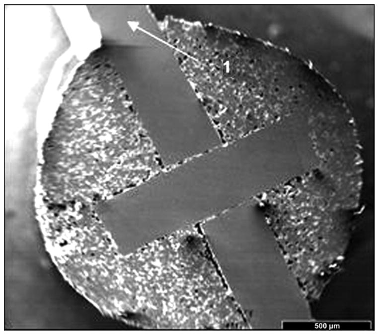
Cross-frame insert with outside fins in skin and bone integrated pylon 3 prototype.
The 4-hour sintering cycle was performed in a Vacuum Industries Super VII furnace (Centorr Vacuum Industries Inc; Nashua, New Hampshire) under vacuum 2.5·10−5 torr. We tried 19 batches of different powder mixture and insert configurations in seven sintering sessions. The sintered samples were examined with use of a scanning electron microscope (SEM). The porosity in these samples varied between 35 and 50 percent, depending on the particle size and the sintering temperature.
Bend Test
A three-point bend test was carried out on all the manufactured experimental samples with use of an Instron 1123 tensile machine (Norwood, Massachusetts) and a three-point bend test fixture. The curves of load P versus the flexural displacement were obtained (Figure 14). The bend strength was calculated as σ = PbL/r3, where Pb is a break load and L is a span distance between the bend points (19 mm in our tests).
Figure 14.
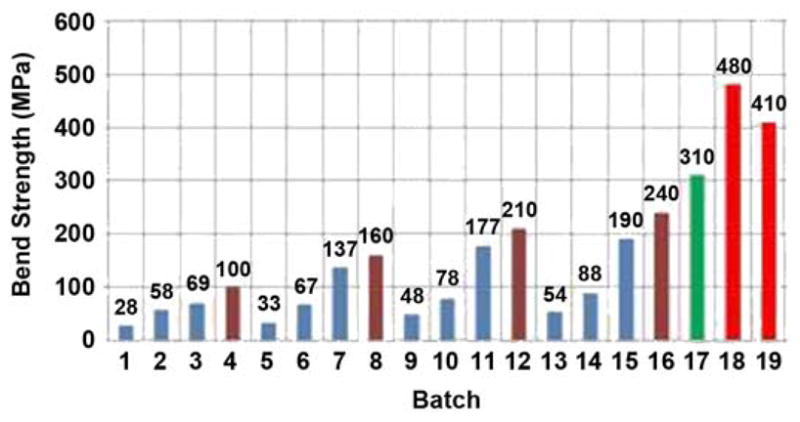
Bend strength of tested samples. Session I: batches 1–4, session II: batches 5–8, session III: batches 9–12, session IV: batches 13–16, session V: batch 17, session VI: batch 18, and session VII: batch 19.
Fatigue Test
The fatigue study was conducted in the Center for Mechanical Characterization of Materials at Case Western Reserve University. The testing consisted of three-point bending with use of a 20,000 lbf servo-hydraulic testing machine (Figure 15) operated at 10 Hz. Loads and loading spans were carefully selected to avoid crushing the porous material under the loading points. Preliminary testing has revealed that such fatigue testing can be conducted on these porous materials. The loads and stresses used were selected based on the load versus displacement traces obtained during quasistatic three-point bend experiments conducted with a span of 19 mm and maximum quasistatic loads ranging from 120 to 160 lbf, corresponding to a maximum stress of 240 MPa. Initial fatigue testing was conducted at a fraction of this maximum stress in order to begin to establish the stress/cycles to failure curve for this material. Fatigue failures at high nominal loads/stresses were observed at a relatively low number of cycles (e.g., 19, 225, and 21,743), consistent with expectations. Reduced loads/stresses produced a significant increase in the number of cycles without failure. The samples tested at 10 Hz at 70 percent of the loads/stresses that produced failure after roughly 20,000 cycles resulted in no failure after 5,000,000 cycles, when the test was terminated. No damage was detected on the sample after 5,000,000 cycles.
Figure 15.
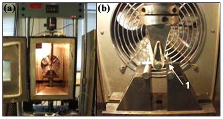
(a) Setup of servo-hydraulic testing machine for fatigue tests at Case Western Reserve University and (b) magnified view of skin and bone integrated pylon 3 sample (1).
In Vivo Animal Experiments
The previously reported animal studies with SBIP-1 and SBIP-2 were conducted at the Pavlov Medical University in St. Petersburg, Russia [6–8]. The studies showed promising results, but the technical capabilities for histopathological analysis were limited. The current studies with SBIP-2 were performed in the United States: one with rats at the Pine Acres Research Facility, Norton, Massachusetts, and the other with a cat at the Georgia Institute of Technology, Atlanta, Georgia. Protocols for the studies were approved by the corresponding Institutional Animal Care and Use Committees.
Skin-Device Interface Study in Rats
Procedure
Two groups of titanium SBIP-2 rods, approximately 1 cm in length and 2 mm in diameter, were prepared. A control rod of polished titanium and an experimental rod were assigned to each of six rats. The rods were thoroughly washed to exclude particulates and were sterilized in a steam autoclave.
Using general anesthesia and sterile techniques, we implanted one of each rod partially through the skin into the subcutaneous space on the back of the rat, lateral to the spine. The rods were implanted through a stab incision in a cranial to caudal direction starting just below the level of the scapula. A 5-0 monocryl suture was placed lateral to the incision and was sutured to the protruding segment of rod; care was taken to exclude the suture from the incision and to avoid strangulating the skin around the incision (Figure 16).
Figure 16.
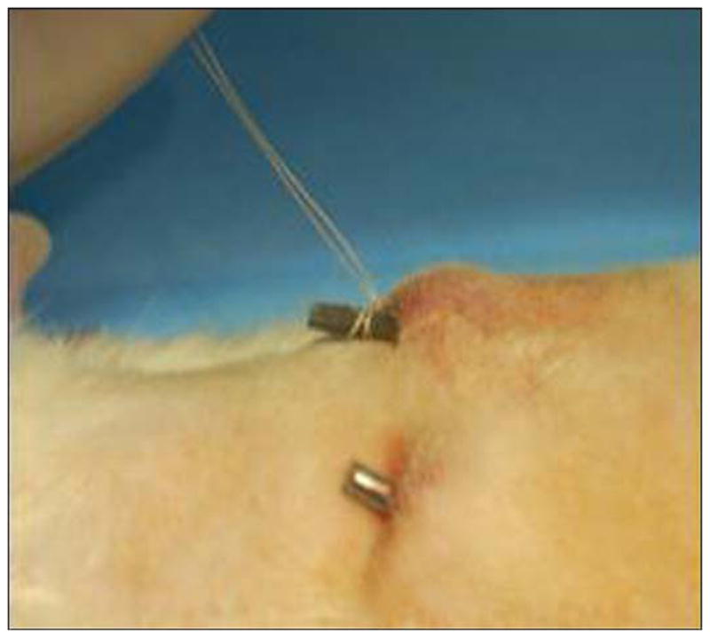
Fixation of implanted skin and bone integrated pylon (SBIP-2) in rat study.
The rats recovered normally and showed no adverse effects from the implants. No immobilization techniques were used. The rats were euthanized with carbon dioxide. Six rats were implanted, and we planned to harvest three each at 3 and 6 weeks. Two of the three rats were to be used to measure the force necessary to remove the rods, while the third was to be evaluated by histopathology. All the control rods were lost spontaneously in the first week of the study, and four of the six experimental rods were lost similarly. Thus, only two rats with experimental rods were available for histopathological study. Rat 452E09397A was euthanized 3 weeks after implantation. During that period, the rat’s weight had increased from 454 to 507 g. Rat 4662162459 was euthanized 8 weeks after implantation. During that period, the rat’s weight had increased from 483 to 672 g. The weight gain was an important indication of the rats’ good health despite the surgical intervention.
Histopathological Analysis
An implanted titanium pylon device with surrounding skin from rat 452E09397A was received in formalin by Charles River Pathology Associates (Frederick, Maryland) for processing and evaluation by Poly-Orth International (Sharon, Massachusetts). Before processing, the study pathologist trimmed the skin surrounding the implant to improve device visualization. The implant was infiltrated and embedded in methyl methacrylate (MMA) according to standard operating procedures. Figure 17 illustrates the embedded tissue and device before slide preparation. A single, approximately 50 μm ground section was obtained through the long axis of the device with use of the Exakt system (Exakt Technologies, Inc; Oklahoma City, Oklahoma). The slide was surface stained with hematoxylin and eosin and examined.
Figure 17.
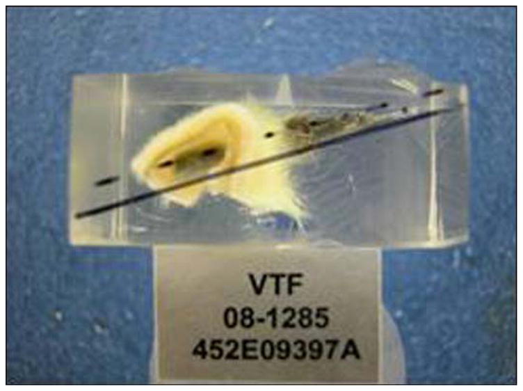
Tissue and rod in methyl methacrylate block before slide preparation.
Bone-Device Interface Study in Cat
Procedure
A porous SBIP-2 pylon, 5 mm in diameter and 4 cm in length, was implanted in the cavity of the residual tibia of one cat during survival surgery under sterile conditions. The cat was induced with ketamine/valium (60–80 μg/kg, subcutaneous) before maintenance with isoflurane anesthesia (1%–3%, intubation).
A temporary tourniquet was placed on the thigh, as is standard for limb amputations. A circumferential surgical incision was made at the level of the distal third of the tibia. The muscles and tendons at this level were transected with use of monopolar cautery. Surgical dissection was undertaken to identify the anterior and posterior neurovascular bundles. The nerves were transected proximal to the level of the planned osteotomy, and the vessels were ligated with use of Vicryl suture. The periosteum was reflected from the exposed tibia proximal to the level of the skin incision. Circumferential control of this tibia was obtained, and a transverse osteotomy was performed at the juncture of the middle and distal thirds of the tibia with use of an oscillating saw. Any remaining soft tissue was transected with use of monopolar cautery, thereby completing the amputation.
The medullary canal of the tibia was broached with use of a curette and carefully widened with the same curette to the diameter of the titanium pin implant. Before closure, the fatty and subcutaneous tissues of the posterior skin flap were sharply excised to the level of the dermis. The wound was copiously irrigated with normal saline and closed with nylon suture so that the dermal portion of the posterior skin flap would directly overlie and contact the distal end of the tibia. A small stab incision was placed with a 15-scalpel blade through the exterior skin into the medullary canal of the tibia. The porous titanium pin was then inserted through this stab incision into the medullary canal of the tibia for a depth of ~2 cm. The skin was then pushed down the pin until it was in good apposition with the cut end of the bone. This procedure allowed for a tight interface between the skin and implant, as well as between the skin and bone. A sterile gauze dressing was applied over the pin through a hole placed in the gauze to further secure the skin-to-pin-to-bone interface. Additional gauze dressing was applied around the pin with sufficient bulk to protect and pad the pin. This dressing was wrapped with veterinary tape to secure it to the thigh and the trunk. The pylon fractured within 1 day of the surgery, leaving a 2 cm segment in the tibia. The bulky dressing was changed 4 days after the procedure, and a new dressing was applied in a similar fashion. Analgesics (transdermal fentanyl patches, 25 μg/h, first 72 hours; buprenorphine, 0.01 mg/kg, subcutaneous, every 8–10 hours) were administered for pain until complete recovery, which took about a week. An antibiotic ceftiofur (4 mg/kg, subcutaneous, once per day) was administered for 10 days after the surgery.
Histopathological Analysis
Four months later, the histological analysis of the removed tibia with the pylon was performed as described previously. The implant was embedded in MMA. Four ~50 μm-thick transverse sections were obtained every 800 to 1,000 μm through the distal end of the device and bone. In addition, one longitudinal section was obtained through the remaining device and bone. All sections were obtained with use of the Exakt system. The transverse slides were surface stained with hematoxylin and eosin and the longitudinal slide was stained with toluidine blue. All slides were examined and photographed.
RESULTS AND DISCUSSION
Development of Composite Porous Pylon
Bend Test Results
A maximum strength of 480 MPa in bend was demonstrated in the SBIP-3 (Figure 13). The chart in Figure 14 shows the bend strength values for samples from all 19 manufactured batches with different mixtures of the titanium particles, sintered at different temperatures. In this chart, blue shows a 50/50 mixture of −30 mesh spheres and −100 mesh sponge; brown shows −100 mesh sponge, no spheres; green shows −270 mesh TiH3 sponge; and red shows −170 mesh TiH3 sponge.
Fatigue Test Results
The samples tested for fatigue at 10 Hz at 70 percent of the loads/stresses that produced failure in roughly 20,000 cycles resulted in no failure after 5,000,000 cycles, when the test was terminated. On fractured samples, we looked at the interface between the solid titanium core and powders near the top and bottom of the cross section (Figure 18). As the SEM images show, these regions appear to be particularly well-bonded.
Figure 18.
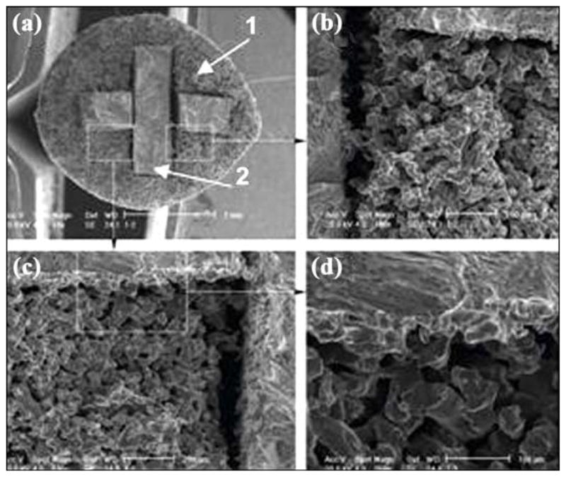
Scanning electron microscopic image of bond between outer part (1) and insert (2) of skin and bone integrated pylon 3. Magnification: (a) 18×, (b) 100×, (c) 100×, and (d) 250×.
Discussion
The minimal yield stress for the material of the implanted pylon for direct skeletal attachment of a limb prosthesis was established earlier to be 200 MPa [6,8]. The estimate was made by consideration of a model for a static load on the implanted pylon [6] and agrees with the study by Frossard and colleagues on the gait of patients with directly attached transfemoral prostheses [17]. Current mechanical testing of the SBIP-3 prototype demonstrated yield stress in the amount of 480 MPa, significantly exceeding the established limit.
The recent promising results of fatigue resistance (5,000,000 cycles) may lead us to use perforated inserts, so as to make the pylons totally permeable and better facilitate cell ingrowth.
Mechanical tests showed that the SBIP-3 prototype with a solid core (insert) significantly exceeded the minimal strength and fatigue requirements. These promising results led us to try to develop a composite pylon structure with total porosity to maintain the best possible biological conductivity for bone and skin. Total porosity would better meet the requirements for tissue sustainability inside the implants. Such a requirement establishes the optimal pore sizes to be 40–500 μm [18–20].
In the case of the SBIP-3 prototype with a 3 mm-wide by 1 mm-thick cross-shaped insert in a 4.3 mm-diameter pylon, the measured flexural modulus for a matrix with 35 volume percent porosity was 5.3 GPa, while the calculated value was 30.8 GPa (Equation (2)). Examination of the deformed sample showed only limited bonding of the titanium particles to the solid insert, and as such, little shear load would be transferred to the porous matrix surrounding the insert. If the entire applied load were supported by the cross-shaped insert, then the true measured flexural modulus would be increased by a factor equal to the ratio of the moments of inertia of the cylindrical shape to the cross shape, since only the cross shape is carrying the imposed load, i.e.,
| (12) |
where 2t is the thickness of the cross insert and h is the height of the insert. For the specified geometry, κ is ~5, indicating that the measured modulus of the beam would be about 20 percent of that predicted. Comparison of the measured (5.3 GPa) and calculated values of bending stiffness (reduced by the above factor of 5, i.e., 6.2 GPa) showed very good agreement. Further analysis of the load deflection data from the bend tests showed that at the point of yield, the maximum bending strain was 1.1 percent, which corresponds well to the expected failure strain of the porous titanium (Equation (7)) of 0.98 percent. The corresponding calculated yield strength of the pylon in bending would be expected to be ~250 MPa.
Recall that the pylon is a composite of layers of materials with widely different elastic moduli, with the stress at any point in the cross section depending on both the strain and material modulus at that point. At the point of yield, the outer surface of the pylon, where the material is the low modulus porous titanium but the axial strain is the highest, the stress is about 100 MPa, whereas at the outer extent of the solid titanium insert, the axial strain is reduced to h/2r of the maximum axial strain and the stress in the much higher modulus solid titanium would be closer to 700 MPa, i.e., very close to the ultimate tensile strength of the titanium itself.
A theoretical study [21] on potential technologies to improve the bond between the implant and bone resulted in the development of the hypothesis that additional side elements (fins) on a cylindrical implant could best serve the purpose. Similar designs (with vent and blades) were introduced in dental implantology in the late 1960s [22–23] but were replaced by cylindrical threaded titanium fixtures developed by Brånemark [24]. We suggest that, despite some similarity in design, the pylons with fins may have better acceptance in the area of direct skeletal attachment of limb prostheses than the vent and blade devices intended for oral implantation. The placement of an implant into the marrow canal of a tube bone fundamentally differs from placement into the tooth root cavity. This argument is based on the natural anisotropy of tube bone remodeling and on the analysis of loosening in total joint replacement methods [21].
Some studies demonstrated that modifications of the surface structure and surface coating improved the interface of surrounding biological tissues with the implant [2]. Our analysis showed that none of the reported techniques addressed the problem of avulsion described many years ago [5,25]. Moreover, we believe that only the “total porosity” approach can potentially create a skin seal that is both free from infection and mechanically sound. Also, any coating in the environment of the hosting biological tissues will disintegrate in a short time compared with the long-life implant usage. Therefore, the effect of the coating should only be considered in the initial period after implantation. Among potential advantages of coating and surface treatment are the acceleration of cell ingrowth and the prevention of infection until a sustainable seal around the implant is established.
By our estimates, the modulus of the totally porous SBIP is three times higher than the modulus of the bone [6], as confirmed by Lee and colleagues [26], but three times lower than the solid devices in the prior art, even when a porous coating is applied. While the “mismatch” problem—the mismatch of moduli of the pylon and hosting tissue—still exists in SBIPs, we will try to minimize the negative outcomes by distributing local pressures with the newly developed SBIP-3 that has external fins.
In Vivo Animal Experiments
Skin-Device Interface (Rat Study) Results
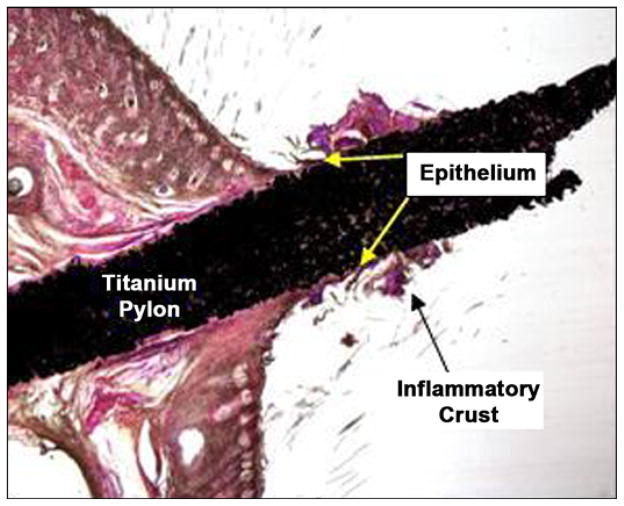
Figure 19 is a low-magnification image of the stained slide. The device was orientated ~90° perpendicular to the skin in the section. The shaft and base of the device within the skin were surrounded by a thin fibrous capsule with minimal inflammatory response. A crust composed of viable and degenerate neutrophils and inflammatory debris formed a cuff around the shaft of the device immediately above the furthest extent of the epithelium. The pores of the device were filled with a fine fibrovascular stroma that extended above the furthest extent of the epithelium.
Figure 19.
Orientation of device in skin (both images 1×, hematoxylin and eosin stain) after 3 weeks of implantation in rats.
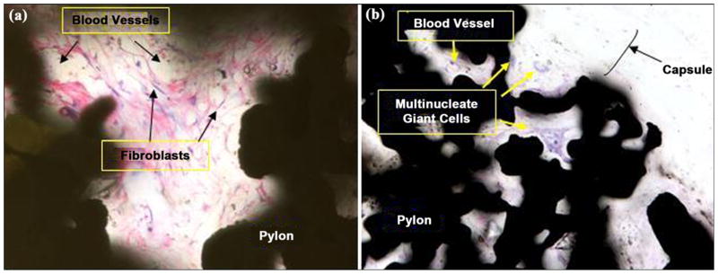
Figure 20(a) and 20(b) illustrates a high magnification image of the fine fibrovascular stroma within the pores of the device in rats 452E09397A and 4662162459, respectively. The loose stroma contains numerous large-caliber thin-walled vessels supported by a meshwork of fibroblasts and sparse collagen. The epidermis and underlying dermis formed a small shoulder at the skin-device interface, with no evidence of pocket formation adjacent to the device. Within the dermis, the device was surrounded by a thin fibrous capsule. Pores within the device were filled by a fine fibrovascular stroma with scattered multinucleate giant cells.
Figure 20.
Close-up of fine fibrovascular tissue within implant pores: (a) rat 452E09397A (40×, hematoxylin and eosin [HE] stain) at 3 weeks after implantation and (b) rat 4662162459 (20×, HE stain) at 9 weeks after implantation.
Bone-Device Interface (Cat Study) Results
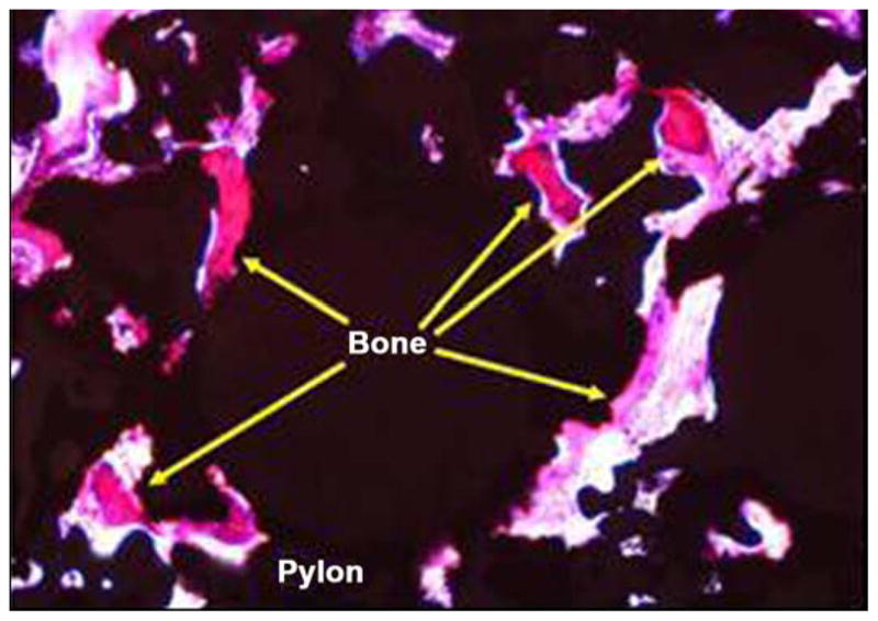
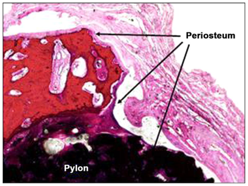
Figure 21 illustrates photomicrographs of the four individual cross sections of the device and surrounding bone. Approximately 30 percent of the circumference of the long bone was absent from the first (most distal) section. Inflammation was not observed within or surrounding the implant. As shown in Figure 22, a continuous band of periosteum covered the fracture and external surfaces of the implant. A near-uniform filling of the internal-device pores with dense fibrous tissue or bone occurred, as illustrated in Figure 23. Minimal to mild proliferation of woven trabecular bone occurred along the endosteal surface in Figure 24. The proliferation was most prominent adjacent to the healing fracture site and extended into the pores of the device in this region. Figure 25 shows a complete longitudinal section of the implant in situ stained with toluidine blue and illustrates bone proliferation within the device pores.
Figure 21.
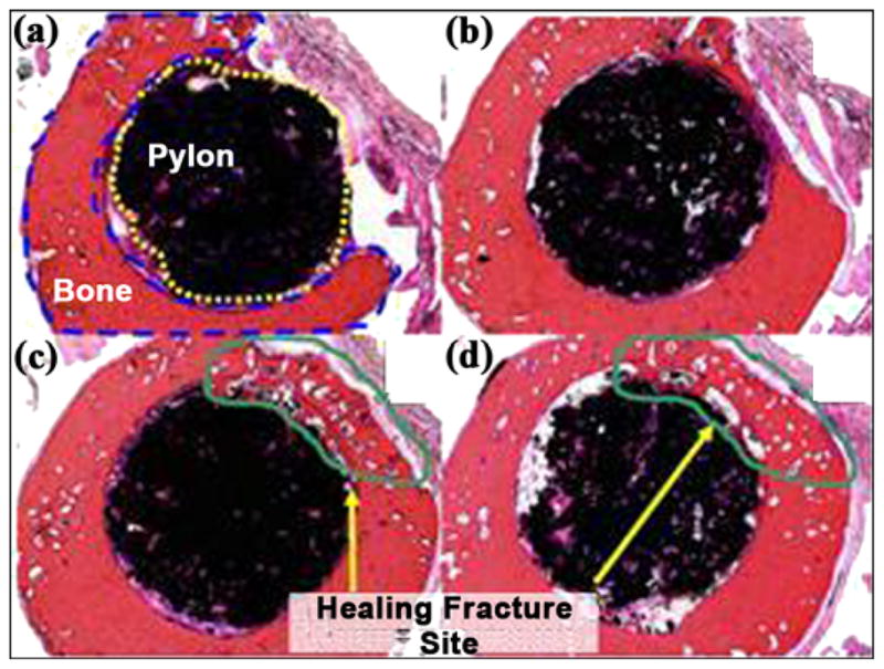
(a)–(d) Cross sections of pylon device in bone from distal to proximal (2×, all hematoxylin and eosin stain).
Figure 22.
Periosteum covering fractured bone and device (4×, hematoxylin and eosin stain).
Figure 23.
Bone formation in pores at center of device (10×, hematoxylin and eosin stain).
Figure 24.
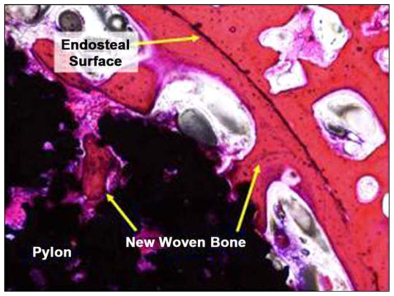
New woven bone on endosteal surface and extending into device pores (10×, hematoxylin and eosin stain).
Figure 25.
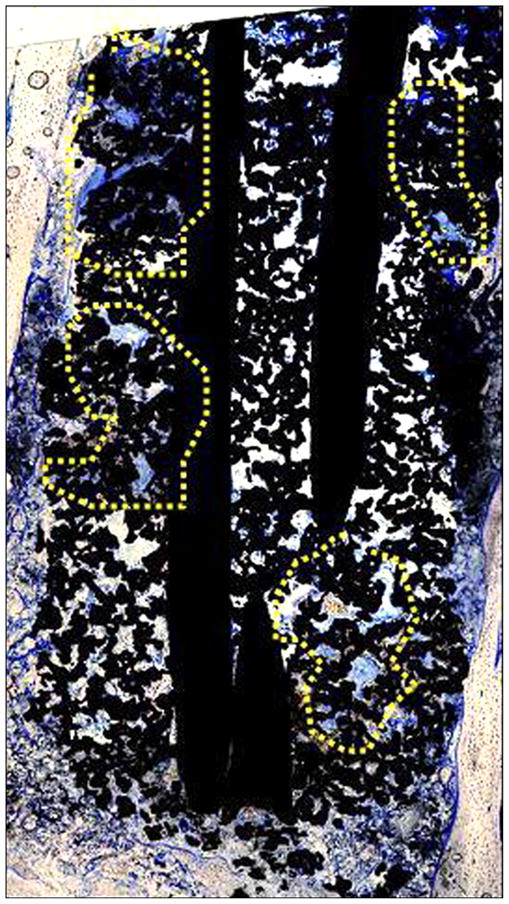
New bone extending into device pores, as indicated by yellow highlighted regions (4× composite image, toluidine blue stain).
Discussion
A titanium pylon implanted into the medullary cavity of a long bone of a cat was well-tolerated with no evidence of inflammation or impaired healing. A continuous band of periosteum extended from the adjacent fracture surface and covered the exposed surface of the implant. The device was surrounded and infiltrated by fibrous tissue and bone within the medullary cavity.
A titanium pylon implanted in the skin of rats was well-tolerated with no evidence of delayed or impaired healing or excessive inflammation. The device was surrounded by a fibrous capsule within the dermis. Pores within the device were filled by a fine fibrovascular stroma free of inflammation. The epidermis extended along the surface of the device and was continuous with the underlying fibrovascular stroma. No evidence of inflammation was observed around the SBIP-2 rod.
Of particular interest is the pattern of epithelial growth on the surface of the rod (Figure 19). The epithelial growth is limited to the surface of the rod, which is above the skin surface, and appears to be self-limiting. This may prevent or inhibit tract formation, leading to implant extrusion due to marsupialization and permigration, as explained by von Recum [5].
CONCLUSIONS
A porous composite structure was developed with strength exceeding that of human bone by a factor of three and with porosity and pore size conducive for skin tissue ingrowth. The animal studies on the porous composite prosthetic pylon demonstrated the ingrowth of skin and bone cells within the pylon, with the potential for the creation of a barrier to infection and a strong bond with the residuum bone. An FEA model was also developed and used for the comparison of stress between bone and the cylindrical prototype (SBIP-2) and between bone and the newly developed prototype with fins (SBIP-3). The FEA model demonstrated its sensitivity to variations in the design of the pylon and can be used to develop design recommendations for minimizing maximal stresses on a bone. The SBIP-3 prototype has been manufactured with newly developed sintering technology with precisely engineered molds made of high density graphite with the capacity for 20 samples per sintering cycle and for multiple uses. The bending strength of the new SBIP-3 was calculated to be 480 MPa, more than two times greater than the minimal level established earlier. First fatigue tests were conducted, with an established initial benchmark of 5,000,000 cycles. First histopathological analysis on pylon-skin and pylon-bone interfaces demonstrated ingrowth and sustainability of the skin and bone tissues in the porous structure.
Acknowledgments
Funding/Support: This material was based on work supported by the National Institutes of Health (grant 1R43HD057492-01A1).
Abbreviations
- 3-D
three-dimensional
- CT
computed tomography
- FEA
finite element analysis
- MMA
methyl methacrylate
- SBIP
skin and bone integrated pylon
- SEM
scanning electron microscope
Footnotes
Author Contributions:
Study concept: M. Pitkin.
Design: M. Pitkin.
Study supervision: M. Pitkin.
Drafting of manuscript: M. Pitkin.
Specification for prototypes: G. Raykhtsaum.
Acquisition of data: G. Raykhtsaum.
Mathematical analysis: J. Pilling.
FEA analysis: Y. Shukeylo.
Interpretation of data: J. Pilling, Y. Shukeylo.
Experimentation in prototyping for testing: V. Moxson, V. Duz.
Acquisition of mechanical testing data and analysis: J. Lewandowski.
Animal study: R. Connolly, J. F. Dalton, B. Prilutsky.
Prosthetic concept for animal study: R. Kistenberg.
Analysis and interpretation of preclinical data: S. Jacobson.
Financial Disclosures: The authors have declared that no competing interests exist.
References
- 1.Brånemark R, Brånemark PI, Rydevik B, Myers RR. Osseo-integration in skeletal reconstruction and rehabilitation: A review. J Rehabil Res Dev. 2001;38(2):175–81. [PubMed] [Google Scholar]
- 2.Pitkin M. On the way to total integration of the prosthetic pylon with residuum. J Rehabil Res Dev. 2009;43(6):345–60. doi: 10.1682/jrrd.2008.08.0112. [DOI] [PMC free article] [PubMed] [Google Scholar]
- 3.Pitkin M, Blinova MI, Yudintseva NV, Potokin IL, Raykhtsaum G, Pinaev GP. Skin and bone integrated prosthetic technology. I. Characterization and morphology of human cells cultivated on titanium implants of different structures [abstract]. Proceedings of the 9th Russian National Congress, People and Health; 2004 Nov 22–26; St. Petersburg, Russia. St. Petersburg (Russia): Russian National Congress; 2004. p. 217. [Google Scholar]
- 4.Pitkin M, Raykhtsaum G, inventors. Skin integrated device. 20070071788. United States patent US. 2007 Mar 29;
- 5.Von Recum AF. Applications and failure modes of percutaneous devices: A review. J Biomed Mater Res. 1984;18(4):323–36. doi: 10.1002/jbm.820180403. [DOI] [PubMed] [Google Scholar]
- 6.Pitkin M, Raykhtsaum G, Pilling J, Galibin OV, Protasov MV, Chihovskaya JV, Belyaeva IG, Blinova MI, Yudintseva NM, Potokin IL, Pinaev GP, Moxson V, Duz V. Porous composite prosthetic pylon for integration with skin and bone. J Rehabil Res Dev. 2007;44(5):723–38. doi: 10.1682/JRRD.2006.12.0160. [DOI] [PMC free article] [PubMed] [Google Scholar]
- 7.Galibin OV, Protasov MV, Chikhovskaya JV, Belyaeva IG, Pitkin M. Skin and bone integrated prosthetic technology. III. An exposed implantation of a porous titanium pellet into the skin [abstract]. Proceedings of the 9th Russian National Congress, People and Health; 2004 Nov 22–26; St. Petersburg, Russia. St. Petersburg: Russian National Congress; 2004. p. 210. [Google Scholar]
- 8.Pitkin M, Raykhtsaum G, Galibin OV, Protasov MV, Chihovskaya JV, Belyaeva IG. Skin and bone integrated prosthetic pylon: A pilot animal study. J Rehabil Res Dev. 2006;43(4):573–80. doi: 10.1682/JRRD.2005.05.0160. [DOI] [PMC free article] [PubMed] [Google Scholar]
- 9.Blinova MI, Yudintseva NV, Kuhareva LV, Goryuhina OA, Potokin IL, Pinaev GP, Pitkin M. Skin and bone integrated prosthetic technology. II. Morphology and growth of cells on implants treated with different proteins [abstract]. Proceedings of the 9th Russian National Congress, People and Health; 2004 Nov 22–26; St. Petersburg, Russia. St. Petersburg (Russia): Russian National Congress; 2004. p. 205. [Google Scholar]
- 10.Yudintseva N, Blinova M, Pinaev G, Potokin I, Pitkin M, Raykhtsaum G. Characterization and morphology of cells cultivated on titanium implants of different structures. 2nd World Congress on Regenerative Medicine; 2005 May 18–20; Leipzig, Germany. Milan (Italy): International Journal of Artificial Organs; 2005. [Google Scholar]
- 11.Pitkin M, inventor. In-bone implantable shaft for prosthetic joints or for direct skeletal attachment of external limb prostheses and method of its installation. 20090062928. United States patent US. 2007 Sep 5;
- 12.Kang YK, Park HC, Youm Y, Lee IK, Ahn MH, Ihn JC. Three dimensional shape reconstruction and finite element analysis of femur before and after the cementless type of total hip replacement. J Biomed Eng. 1993;15(6):497–504. doi: 10.1016/0141-5425(93)90065-7. [DOI] [PubMed] [Google Scholar]
- 13.Xu W, Xu DH, Crocombe AD. Three-dimensional finite element stress and strain analysis of a transfemoral osseointegration implant. Proc Inst Mech Eng [H] 2006;220(6):661–70. doi: 10.1243/09544119JEIM84. [DOI] [PubMed] [Google Scholar]
- 14.Clift SE, Fisher J, Watson CJ. Stress and strain distribution in the bone surrounding a new design of dental implant: A comparison with a threaded Branemark type implant. Proc Inst Mech Eng [H] 1993;207(3):133–38. doi: 10.1243/PIME_PROC_1993_207_285_02. [DOI] [PubMed] [Google Scholar]
- 15.Weinans H, Sumner DR, Igloria R, Natarajan RN. Sensitivity of periprosthetic stress-shielding to load and the bone density-modulus relationship in subject-specific finite element models. J Biomech. 2000;33(7):809–17. doi: 10.1016/S0021-9290(00)00036-1. [DOI] [PubMed] [Google Scholar]
- 16.Choi K, Kuhn JL, Ciarelli MJ, Goldstein SA. The elastic moduli of human subchondral, trabecular, and cortical bone tissue and the size-dependency of cortical bone modulus. J Biomech. 1990;23(11):1103–13. doi: 10.1016/0021-9290(90)90003-L. [DOI] [PubMed] [Google Scholar]
- 17.Frossard L, Stevenson N, Smeathers J, Häggström E, Hagberg K, Sullivan J, Ewins D, Gow DL, Gray S, Brånemark R. Monitoring of the load regime applied on the osseointegrated fixation of a trans-femoral amputee: A tool for evidence-based practice. Prosthet Orthot Int. 2008;32(1):68–78. doi: 10.1080/03093640701676319. [DOI] [PubMed] [Google Scholar]
- 18.Daly BDT, Szycher M, Worthington M, Poirier VL, Warren RG. Annual progress report of National Institutes of Health, report No. NO1-HV-8-2919-2, Accession No. PB81109381. Springfield (VA): National Technical Information Service; 1980. Development of percutaneous energy transmission systems. [Google Scholar]
- 19.Pendegrass CJ, Goodship AE, Blunn GW. Development of a soft tissue seal around bone-anchored transcutaneous amputation prostheses. Biomaterials. 2006;27(23):4183–91. doi: 10.1016/j.biomaterials.2006.03.041. [DOI] [PubMed] [Google Scholar]
- 20.Aaron RK, Morgan JR. Biohybrid limbs: New materials and new properties. Med Health R I. 2007;90(1):4–6. [PubMed] [Google Scholar]
- 21.Pitkin M. One lesson from arthroplasty to osseointegration in search for better fixation of in-bone implanted prosthesis. J Rehabil Res Dev. 2008;45(4):vii–xiv. [PMC free article] [PubMed] [Google Scholar]
- 22.Linkow LI. The blade vent—A new dimension in endosseous implantology. Dent Concepts. 1968;11(2):3–12. [PubMed] [Google Scholar]
- 23.Linkow LI, Donath K, Lemons JE. Retrieval analyses of a blade implant after 231 months of clinical function. Implant Dent. 1992;1(1):37–43. doi: 10.1097/00008505-199200110-00004. [DOI] [PubMed] [Google Scholar]
- 24.Brånemark PI, inventor; Medevelop AB, assignee. Anchoring element for implantation in tissue, for holding prosthesis, artificial joint components or the like. 5702445. United States patent US. 1997 Dec 20;
- 25.Hall CW, Adams LM, Ghidoni JJ. Development of skin interfacing cannula. Trans Am Soc Artif Intern Organs. 1975;21:281–88. [PubMed] [Google Scholar]
- 26.Lee WC, Frossard LA, Hagberg K, Haggstrom E, Gow DL, Gray S, Brånemark R. Magnitude and variability of loading on the osseointegrated implant of transfemoral amputees during walking. Med Eng Phys. 2008;30(7):825–33. doi: 10.1016/j.medengphy.2007.09.003. [DOI] [PubMed] [Google Scholar]


