Abstract
Electric fatigue tests have been conducted on pure and manganese modified Pb(In0.5Nb0.5)O3-Pb(Mg1/3Nb2/3)O3-PbTiO3 (PIN-PMN-PT) single crystals along different crystallographic directions. Polarization degradation was observed to suddenly occur above 50–100 bipolar cycles in <110> oriented samples, while <001> oriented samples exhibited almost fatigue free characteristics. The fatigue behavior was investigated as a function of orientation, magnitude of the electric field and manganese dopant. It was found that <001> oriented PIN-PMN-PT crystals were fatigue free, due to its small domain size, being on the order of 1µm. The <110> direction exhibited a strong electrical fatigue behavior due to mechanical degradation. Micro/macro cracks were developed in fatigued <110> oriented single crystals. Fatigue and cracks were the results of strong anisotropic piezoelectric stress and non-180° domain switching, which completely locked the non-180° domains. Furthermore, manganese modified PIN-PMN-PT crystals were found to show improved fatigue behavior due to its enhanced coercive field.
Keywords: Ferroelectricity, Piezoelectricity, Fatigue, Internal stresses, Perovskite crystal
I. Introduction
Polarization fatigue in a ferroelectric material is defined as a systematic loss of the switchable polarization under cyclic electric field, believed to reduce the remnant polarization, dielectric permittivity and piezoelectric coefficients. Fatigue has the potential to severely limit the application of these materials. There are numerous publications and reports discussing the origin of ferroelectric fatigue. Reviews on polarization fatigue were focused on ferroelectric thin films, bulk ceramics and single crystals in last decade.1–3 Many factors were found to affect the fatigue behavior in ferroelectric materials, including experimental parameters, such as the applied driving field amplitude (related to coercive field, or field level to induce phase transition), driving field frequency, temperature; the electrode attachment, electrode-ferroelectric interface quality, crystal microstructure, grain size, porosity, doping, anisotropy, etc. Various mechanisms have been explored to explain the fatigue behavior, such as domain –wall pinning by point defect agglomeration and space charge accumulation; dead/blocking interfacial layers; nucleation inhibition; local phase decomposition and the formation of microcracks, to name a few.1–18 However, most of these results were based upon thin films and bulk polycrystalline ceramic, which are highly dependent on surface, interface and grain boundary related imperfections and defects. Thus, it is desirable to investigate the fatigue behavior in single crystals to better understand the ferroelectric characteristics in bulk materials, in order to decouple the fatigue behavior from the impact of surface/interface related imperfections and grain boundary conditions19.
In last few years, many investigations on ferroelectric single crystals, including Pb(Mg1/3Nb2/3)O3-PbTiO3 (PMNT) and Pb(Zn1/3Nb2/3)O3-PbTiO3 (PZNT), were carried out and the results show that fatigue in single crystals exhibits strong anisotropic behavior, however, the reported results on the anisotropy were rather contradictory.19–28 In PZNT crystals, it was reported that <001> crystallographic direction is fatigue-resistant, while the <111> direction exhibit a strong fatigue behavior due to accumulated defects. Vacancies or space charge defects were found to accumulate at domain boundaries during switching and clamp their motion. Studies have shown that the activation energy for the domain motion is dependent on the crystallographic orientation in PZNT crystals and that the mobility is maximum along the <001> direction.19–23 In PMNT crystals, however, it was observed that microcracks developed in <001> oriented crystals during the cyclic electric field that pin the domain wall motion, leading to polarization degradation.24–28 They attribute the domain boundary cracking to 71° domain switching observed by in-situ transmission electron microscopy.
In the last few years, a new relaxor-based ternary single crystal system Pb(In1/2Nb1/2)O3-Pb(Mg1/3Nb2/3)O3-PbTiO3 (PIN-PMN-PT) was reported to possess higher Curie temperature/ferroelectric phase transition temperature and comparable piezoelectric properties to the binary crystal systems PZNT/PMNT. As a result, PIN-PMN-PT shows broadened temperature usage range.29–33 Thus, it is interesting to explore this ternary crystal system for better understanding its performance under different external conditions, such as dc bias, stress, cyclic electric field, etc. The present investigation is concerned with the fatigue behavior in PIN-PMN-PT crystals. The effects of orientation, including <001> and <110> directions, applied electric field amplitude and acceptor dopants on fatigue behavior in the crystals will be investigated and a possible fatigue mechanism for the crystals will be discussed.
II. Experimental
Pure and manganese modified PIN-PMN-PT single crystals were grown by a modified Bridgman technique, along the crystallographic <001> direction. The composition used in this study was selected far away from its morphotropic phase boundary (MPB), in order to avoid composition induced phase transition interference during the cyclic period. The piezoelectric coefficient d33 of this PIN-PMN-PT composition was found to be 1300pC/N, while the remnant polarization Pr and coercive field EC were on the order of 0.27C/m2 and 5kV/cm, respectively, corresponding to part B of the as-grown crystal boule29, with composition of 0.26PIN-0.45PMN-0.29PT. The crystal was oriented along <001> and <110> directions using a back-reflection Laue system. The samples were cut and polished with silicon carbide. The dimension of the obtained samples was 5×5×0.5mm3, with normal direction along <001> and <110>. In order to eliminate the electrode material and interface issues and keep the results consistent, vacuum gold sputtered electrodes were used for all the samples. High field measurements of polarization and strain were performed by a modified Sawyer-Tower circuit and linear variable differential transducer (LVDT), driven by a lock-in amplifier. Based on the polarization measurement as a function of frequency, the remnant polarization was found to drop sharply at 800Hz for PIN-PMN-PT crystals, thus, the domain switching time was determined to be on the order of a few milliseconds. Thus, all the fatigue measurement frequency was selected to be 10Hz, with a triangular waveform. The amplitude of the applied electric field was selected according to the coercive field of the crystals, being on the order of 5–15kV/cm. In order to prevent electric breakdown and keep the sample temperature constant under cyclic electric loading, the samples were immersed in a silicone oil tank. Scanning electron microscope (SEM) was used to observe the domain configuration in fatigued samples with different orientations. X-ray diffraction was also performed on the fatigued samples to check for phase changes.
III. Experimental Results
3.1 Anisotropic fatigue behavior in single crystal systems
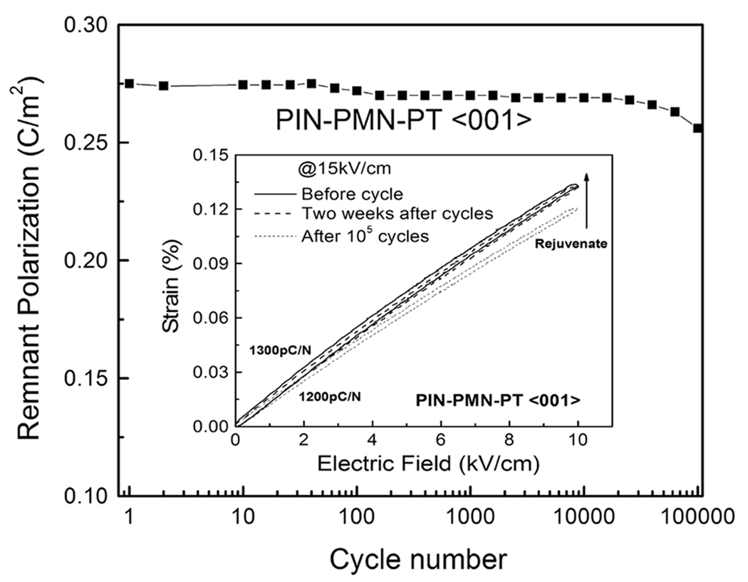
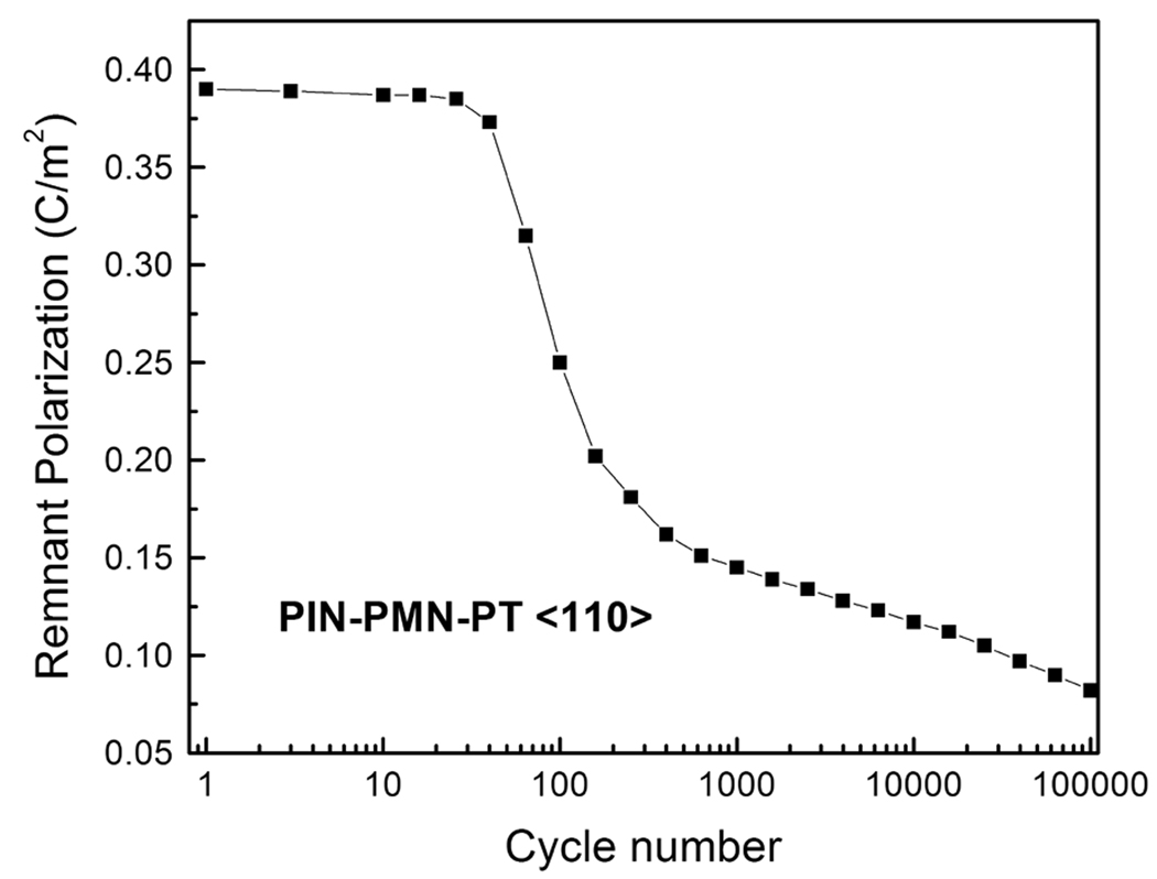
Fig. 1a shows the remnant polarization (Pr) for <001> oriented PIN-PMN-PT crystals, as a function of the number of switching cycles. The amplitude of the applied alternating triangular electric field was 15kV/cm. The initial Pr was found to be on the order of 0.27C/m2, maintaining the same value till > 104 cycles. Pr was slightly reduced to 0.26C/m2 at the cycle about 105. The unipolar strain behavior is given in the small inset. The piezoelectric coefficient d33 calculated from the slope of the S-E loop was found to be on the order of 1300pC/N before the fatigue test, and the value slightly decreased to 1200pC/N after 105 cycles. However, the maxima strain level was recovered after two weeks, indicating the rejuvenate behavior for <001> oriented samples. Fig. 1b shows the fatigue behavior for <110> oriented PIN-PMN-PT crystals, with the same measurement conditions. It is clearly observed that there were three stages in the polarization as function of cycling number: 1) the slow fatigue stage (up to 30 cycles), 2) the logarithmic stage (around 50 to 103 cycles) and 3) the saturated stage (after 103 cycles). The fatigue was found to occur rather suddenly after 50 cycles, with polarization Pr decreasing from 0.39C/m2 to only 0.15C/m2 in the logarithmic stage.
Fig. 1.
Polarization as function of number of cycles for <001> (a) and <110> (b) oriented PIN-PMN-PT crystals at field magnitude of 15kV/cm, the small inset shows unipolar strain as function of field for <001> oriented crystals before and after 105 cycles.
3.2 The effect of manganese dopants on the fatigue characteristics
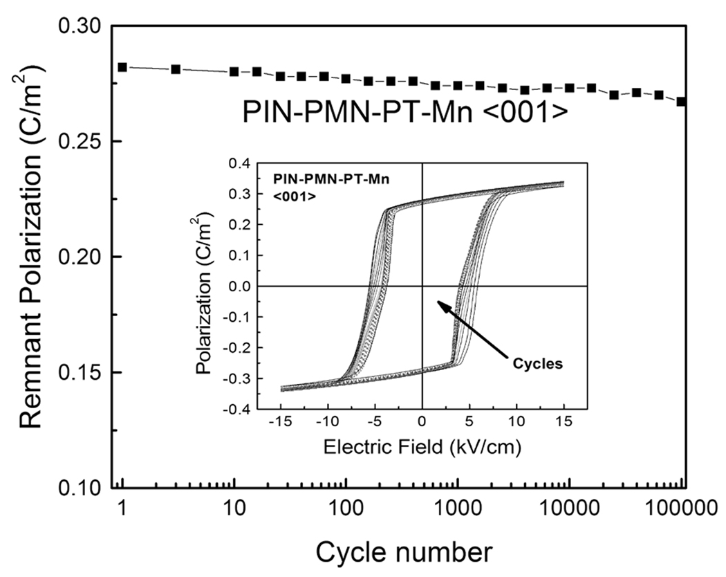
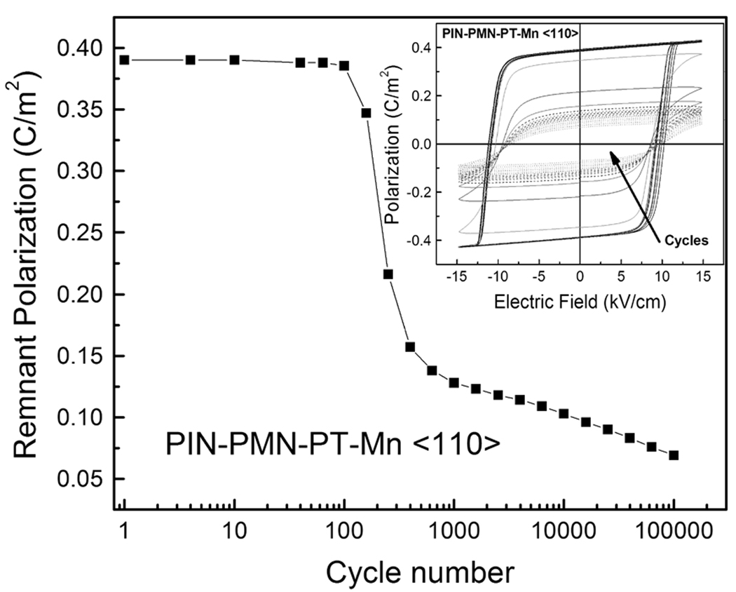
Manganese modified PIN-PMN-PT single crystals were found to possess higher mechanical quality factor (Q33 ~800–1000) and coercive field (EC ~5.7–10kV/cm), with internal bias Eint being on the order of 0.1–0.5kV/cm, showing a “hardening” characteristic, presumably due to the oxygen vacancy- acceptor defect dipole, clamping the domain wall motion. The fatigue behavior for <001> and <110> oriented Mn modified PIN-PMN-PT crystals were shown in Fig. 2a and Fig. 2b, respectively. The small insets in the figures were bipolar polarization as a function of electric field and cycling number. It was found that the fatigue behaviors were very similar to the pure PIN-PMN-PT crystals, where the Pr was found to be 0.28C/m2 for <001> oriented Mn doped crystals, slightly decreased to 0.27C/m2 at cycle number 105, while the Pr was found to be 0.39C/m2 for <110> oriented doped crystals and maintain the same value till 100 cycles, then dropped suddenly to only 0.13C/m2 at 1000 cycles.
Fig. 2.
Polarization as function of number of cycles for <001> (a) and <110> (b) oriented Mn- doped PIN-PMN-PT crystals at field magnitude of 15kV/cm, the small insets show polarization hysteresis as function of field and cycle number.
3.3 The effect of amplitude of the cyclic electric field on the fatigue behavior
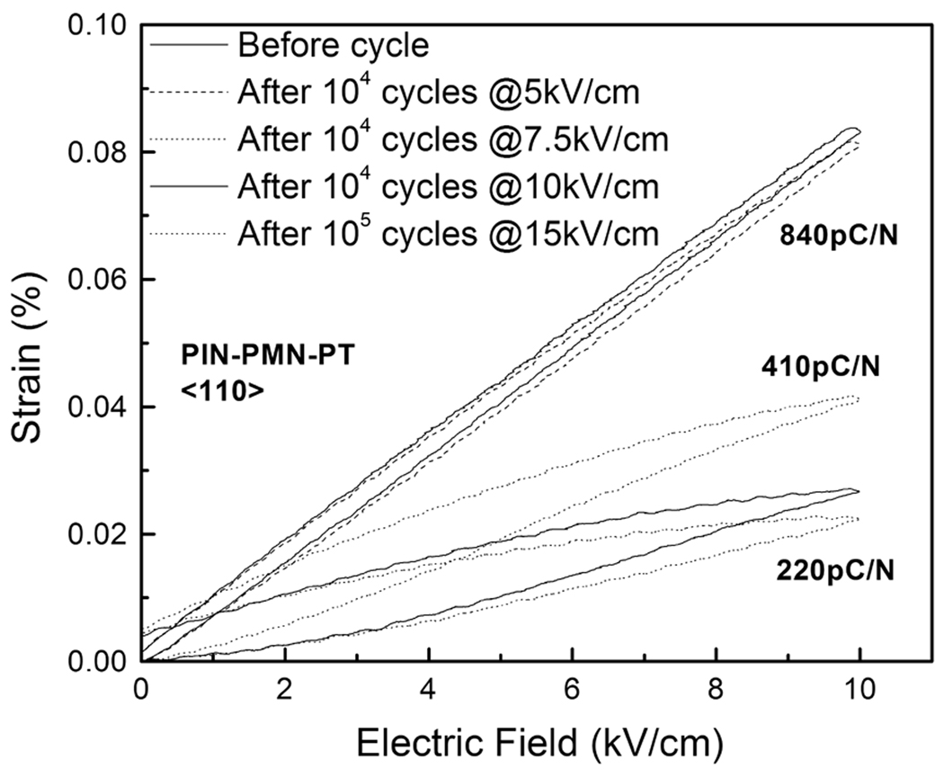
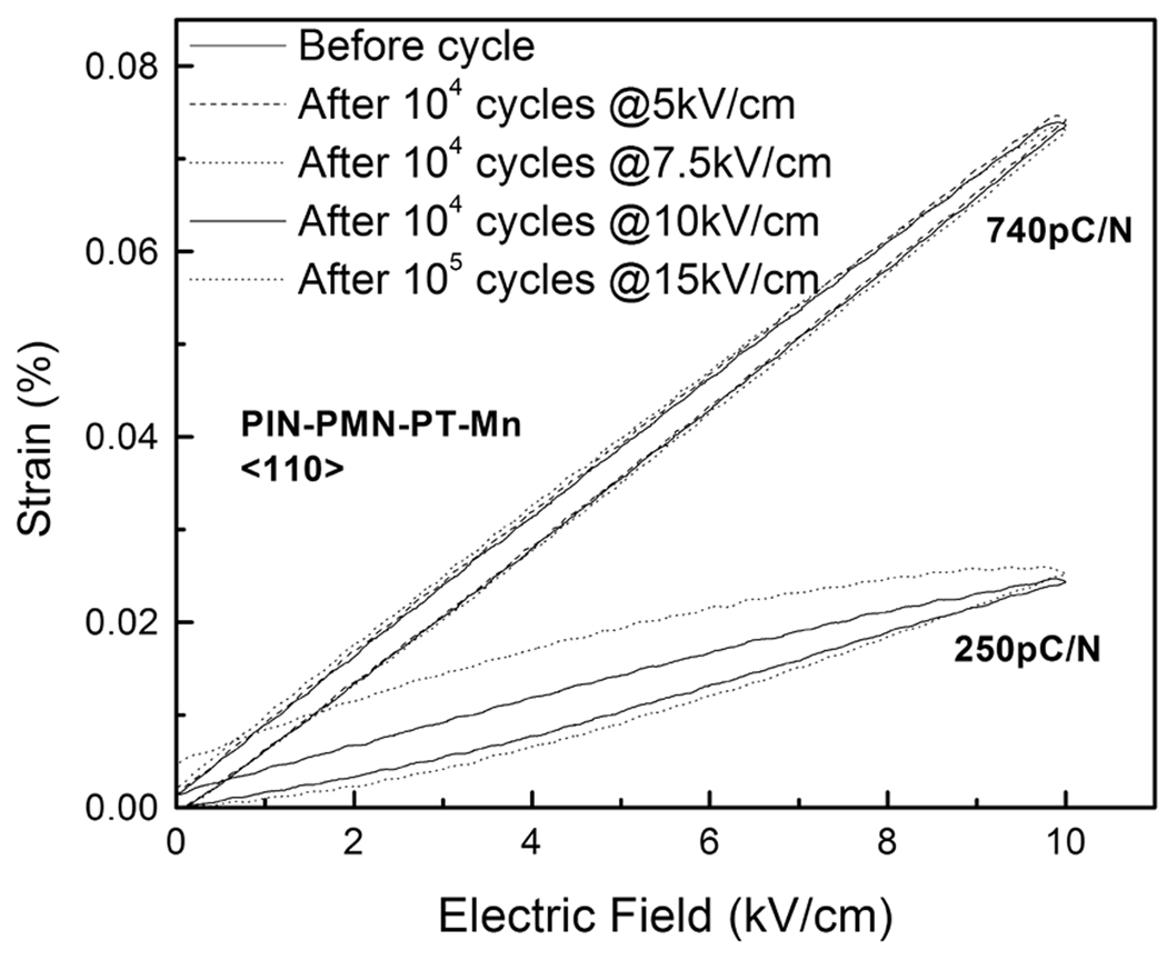
Fig. 3a shows the unipolar strain measured at 10kV/cm for <110> oriented PIN-PMN-PT crystals immediately after the fatigue measurements with different amplitudes of the cyclic electric field. It was observed that the <110> oriented crystals show no fatigue when the amplitude of the applied field was on the order of 5kV/cm (the same value of Ec). The piezoelectric coefficient was calculated to be 840pC/N, which is similar to that of the virgin samples. However, strong fatigue was found to occur when the applied electric field exceeded the coercive field. Degraded piezoelectric coefficients were measured to be on the order of 410pC/N to only 220pC/N, with increasing amplitude of the cyclic electric fields. For comparison, the unipolar strain for <110> oriented Mn- modified PIN-PMN-PT crystals were presented in Fig. 3b following the same fatigue measurements. It was found that the Mn- modified crystals show improved fatigue resistance, with fatigue-free behavior until the applied cyclic electric field reached 7.5kV/cm. Fatigue started in the samples when electric field exceeded 10kV/cm. Piezoelectric values were reduced to ~250pC/N, only one third of the original value.
Fig. 3.
Unipolar strain behavior after fatigue measurement under different applied field amplitudes for <110> oriented pure (a) and Mn-doped (b) PIN-PMN-PT crystals.
IV. Discussion
4.1 Anisotropic engineered domain configuration
PIN-PMN-PT single crystals show strong anisotropic fatigue behavior. The <001> direction shows almost fatigue resistant characteristics, while <110> and <111> directions exhibit strong polarization degradation with cyclic electric field. In perovskite ferroelectric, it is known that defects, such as vacancies or space charges, tend to accumulate at domain boundaries during switching and prevent their free motion and reduce the polarization.19 For a <001> poled rhombohedral ferroelectric single crystal, the original eight equivalent polarization variants along <111> rotate toward the <001> direction and reduce to four partially aligned variants by 180° domain switching, forming a degenerated “4R” engineered domain configuration34. For <110> oriented crystals, when the field is applied along the <110> direction, another domain engineered structure “2R” was generated34, with two equivalent variants forming a domain boundaries in the <001> direction. In <001> oriented PIN-PMN-PT single crystals, the polarization reduction was found to be on the order of <5% upon 105 cycles, correspondingly, the decreasing of piezoelectric coefficient was found to be <8%. The piezoelectric coefficient was found to rejuvenate to the original value after two weeks and/or thermal treatment at 300°C, revealing that the frozen-in pinning centers at the domain boundaries, such as agglomerated defect/charge, were removed and/or re-distributed; hence, the domain wall mobility recovered. Of particular interest is the fatigue behavior in manganese modified PIN-PMN-PT single crystals, which show similar trends with cycling number to the pure counterpart. The manganese ions are known to be acceptor dopants in the relaxor-PT materials, which substitute titanium ions, resulting in the development of acceptor-oxygen vacancy defect dipoles, clamping/pinning the domain wall motion. The acceptor dopants in the bulk crystal systems are supposed to deteriorate the fatigue behavior; however, the manganese addition in PIN-PMN-PT single crystals was found to improve the fatigue resistance. This is thought to be related to its higher coercive field, which will be discussed in detail in the following section.
4.2 Coercive field and the amplitude of applied field
It was reported that the coercive field of the materials was an important factor affecting the fatigue characteristics. Little or no fatigue was found for an applied electric field around/below the coercive field (EC) and moderate fatigue for a field between EC and 2EC, while the most severe fatigue occurs for the samples driven by a saturated field of above 2EC1. The EC of Mn doped PIN-PMN-PT crystals was found to be 5.7kV/cm and 10kV/cm for <001> and <110> orientations, respectively, higher than those values reported for pure crystals. Thus, in Mn- doped crystals, the fatigue behavior is affected by the density of acceptor-oxygen vacancy defects and coercive field, where high defect density deteriorates the fatigue while high coercive field improves the fatigue. In order to delineate which mechanism dominates the fatigue behavior, experiments were performed on the pure and Mn-doped <110> oriented PIN-PMN-PT crystals. As shown in Fig. 3a and Fig. 3b, both <110> oriented pure and doped crystals show fatigue resistance when the electric field was on the order of 5kV/cm and exhibited strong fatigue behavior with the applied field being on the order of 15kV/cm. However, when the field was on the order of 7.5kV/cm, the pure PIN-PMN-PT was found to exhibit fatigue behavior, with piezoelectric coefficient being only half of the value for virgin samples, while the Mn-doped crystals show fatigue free behavior, due to its higher EC. It was observed at the same high applied field (15kV/cm), the strain hysteresis for Mn- doped crystals was found to be higher than that of the pure counterpart, revealing that fatigue is more severe in Mn-doped crystals, since the strain hysteresis is related to the microcracks inside the bulk crystals, which induced by the stress from accumulated defects. So the defect density will control the fatigue behavior in Mn-doped PIN-PMN-PT crystals at high cyclic field, while the high coercive field will dominate the fatigue at relatively low cyclic field.
4.3 Mechanical failure (cracking)
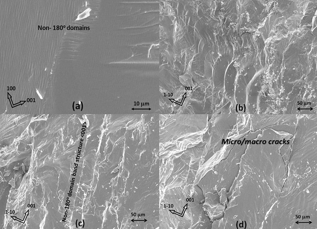
Both first-principles calculations and experimental results with respect to ferroelectrics have shown that the application of a mechanical stress can impact polarizations and their switching behavior due to the stress induced micro/macro cracks and phase transitions19,35,36. Fig. 4 shows the SEM images of <001> and <110> oriented PIN-PMN-PT crystal samples after 105 bipolar cycles. Typical domain pattern for <001> oriented crystals was observed and shown in Fig. 4a. The non-180° domain twins were found to be parallel and/or vertical to the <101> direction, with domain size being on the order of <1 micron. The domain twins join together on the (101) crystallographic plane. Fig. 4b– 4d show the images of fatigued <110> oriented samples. The domain size in <110> oriented samples was found to be on the order of 10 microns, much larger when compared to the domain size in <001> oriented crystals. Fig. 4b shows the (110) cleavage planes, parallel to which, the cracks are easy to occur. Fig. 4c gives the non-180° domain band structure (domain boundary) along the <001> direction. Fig. 4d shows micro/macro cracks, which are in the range of few tens to few hundreds microns. The cracks propagate along the domain boundary in the <001> direction, due to the large strain incompatibility. Also, other cracks were observed that deviated from the domain boundaries, which were mainly due to discontinuities and the anisotropic nature of the mechanical displacement. Analogous to <110> oriented PMNT crystals28, sudden crack initiation was assumed to occur within the first hundred cycles and propagate quickly under the first thousand cycles, but afterward there is almost no crack propagation, corresponding to the logarithmic stage in Fig. 1b and Fig. 2b. To further elucidate the evolution of residual stress associated with the crystallographic orientations in PIN-PMN-PT single crystals, more experiments and discussions will be followed.
Fig. 4.
SEM images of PIN-PMN-PT crystals after fatigue test. <001> oriented sample (a); <110> oriented samples showing (110) cleavage planes (b); non-180° domain band structure (c); micro/macro cracks (d).
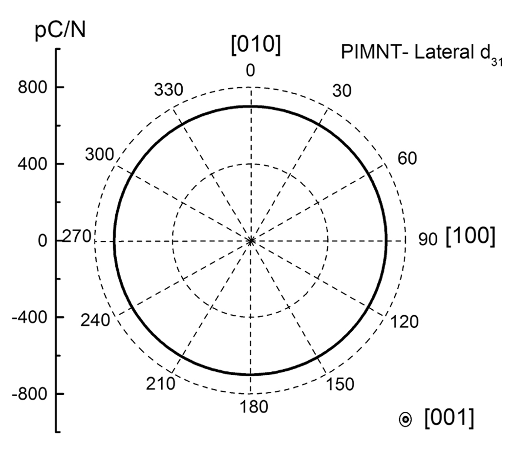
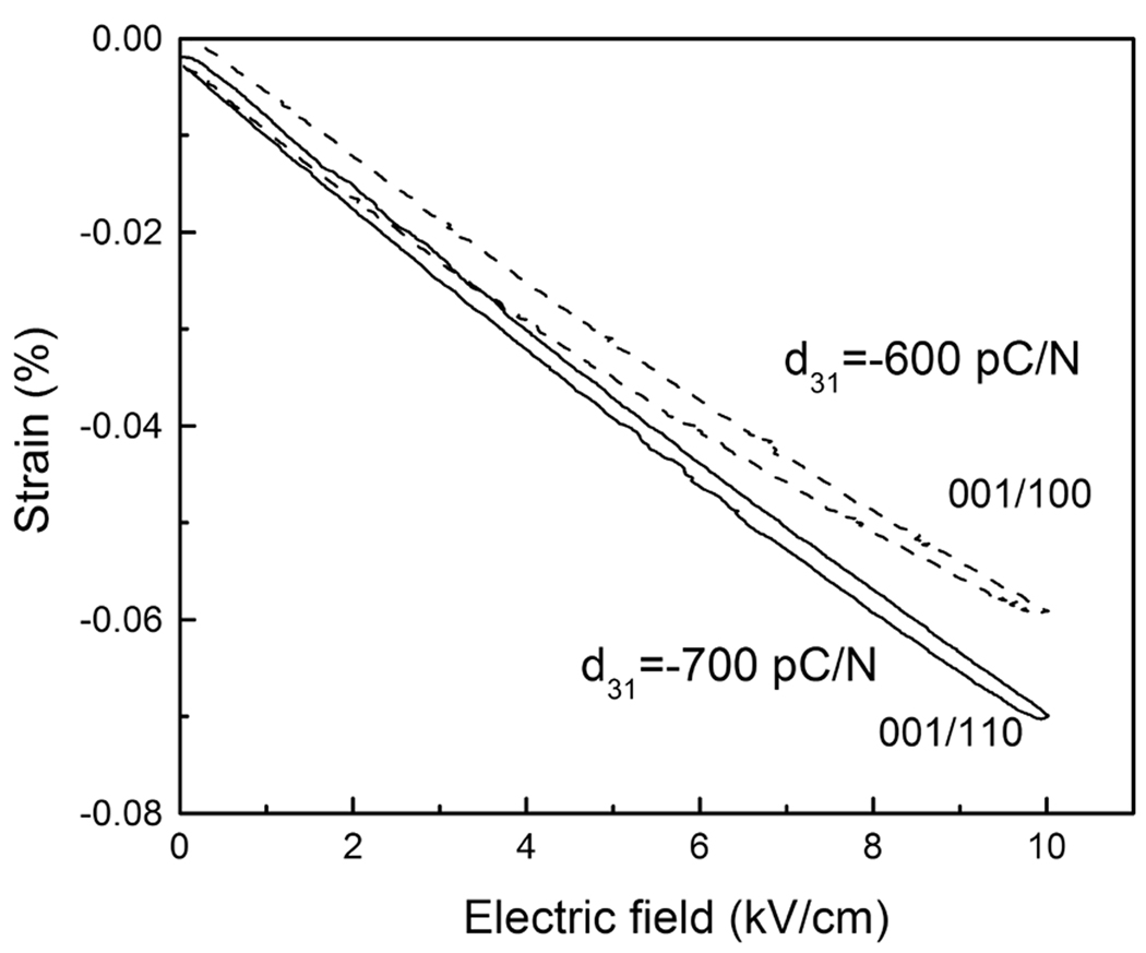
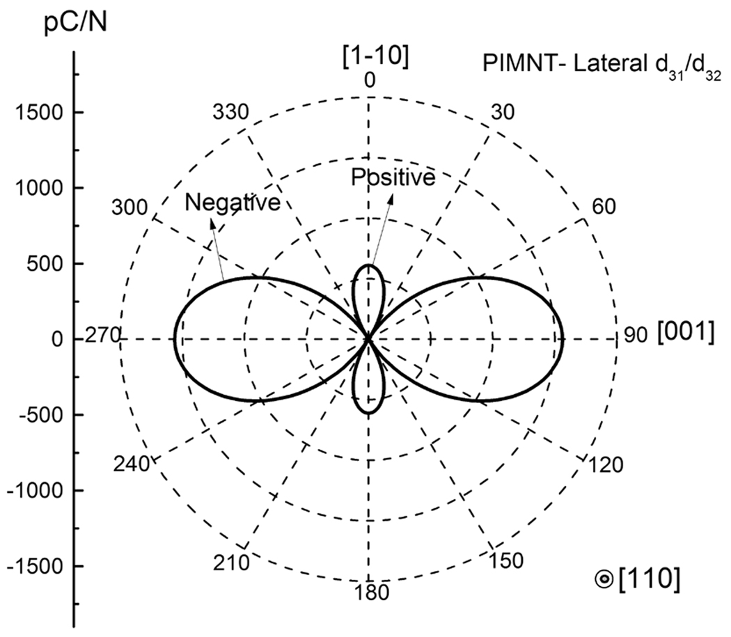
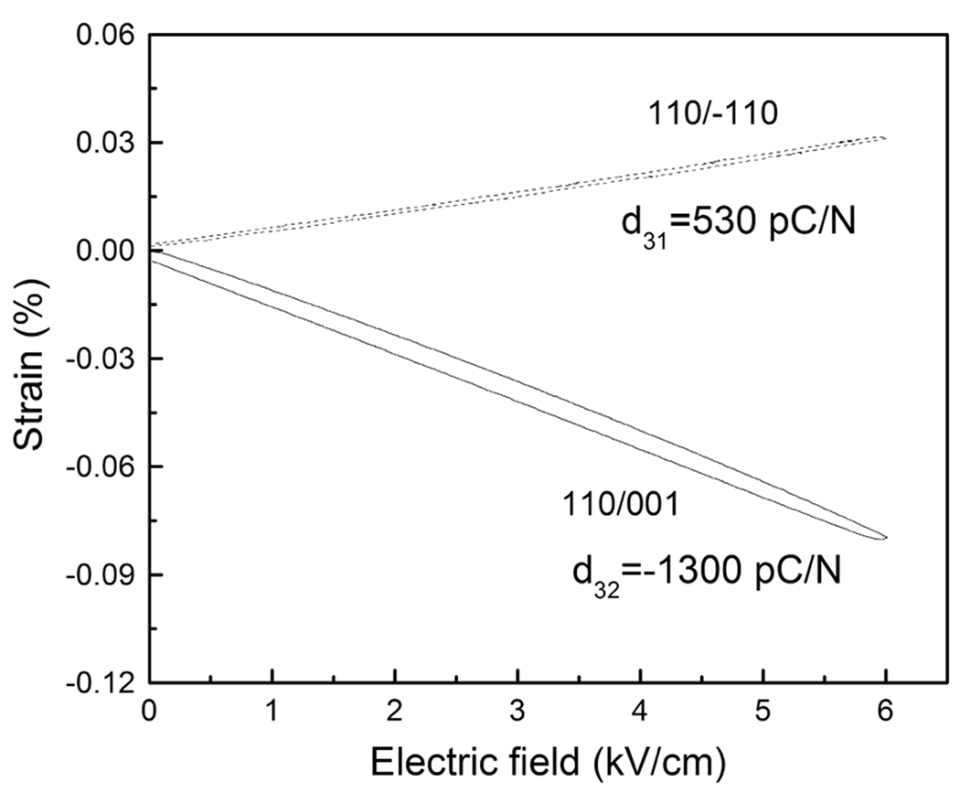
In crystals, when the applied field was along the crystallographic orientation, the stress tensor has lateral components perpendicular to the field direction, which is related to the lateral piezoelectric coefficient d31 and/or d32. Fig. 5a shows the lateral piezoelectric coefficient map for <001> poled PIN-PMN-PT crystals, from which the d31 values were found to be the same for different vibration directions. This is confirmed in Fig. 5b, where the field induced strain/displacement was found to be on the same order. For <110> oriented crystals, however, it is in “2R” engineered domain configuration and the macroscopic symmetry is mm2, so the lateral piezoelectric coefficient was found to vary significantly along different vibration directions, as shown in Fig. 6a, where the maximum value d32 can be achieved when the sample vibrates along <001> direction, being on the order of −1300pC/N (d32), while the piezoelectric coefficient d31 was found to be 530pC/N when vibrate along <1–10> direction. Of particular importance is that the crystal will be contracted along <001> direction and expanded along <1–10> direction when applied field is along <110> direction, giving rise to a large strain/displacement discontinuity along lateral directions, as confirmed in Fig. 6b. The generated strain/displacement discontinuity will induce the mechanical fatigue by buildup of the resistance to the non-180° domain wall motion. As the resistance increases, a great part of the strain is accommodated by plastic deformation, cracks start to form when the deformation reaches a certain threshold under cyclic field. Due to the different levels of strain generated in <110> oriented samples, the generated cracks will deviate from the domain boundaries, which will usually be along the <001> direction.
Fig. 5.
(a) Lateral piezoelectric coefficient map for <001> poled crystals; (b) Unipolar strain curves for <001> poled crystals and vibrate along <110> and <100>.
Fig. 6.
(a) Lateral piezoelectric coefficient map for <110> poled crystals; (b) Unipolar strain curves for <110> poled crystals and vibrate along <001> and <1–10>.
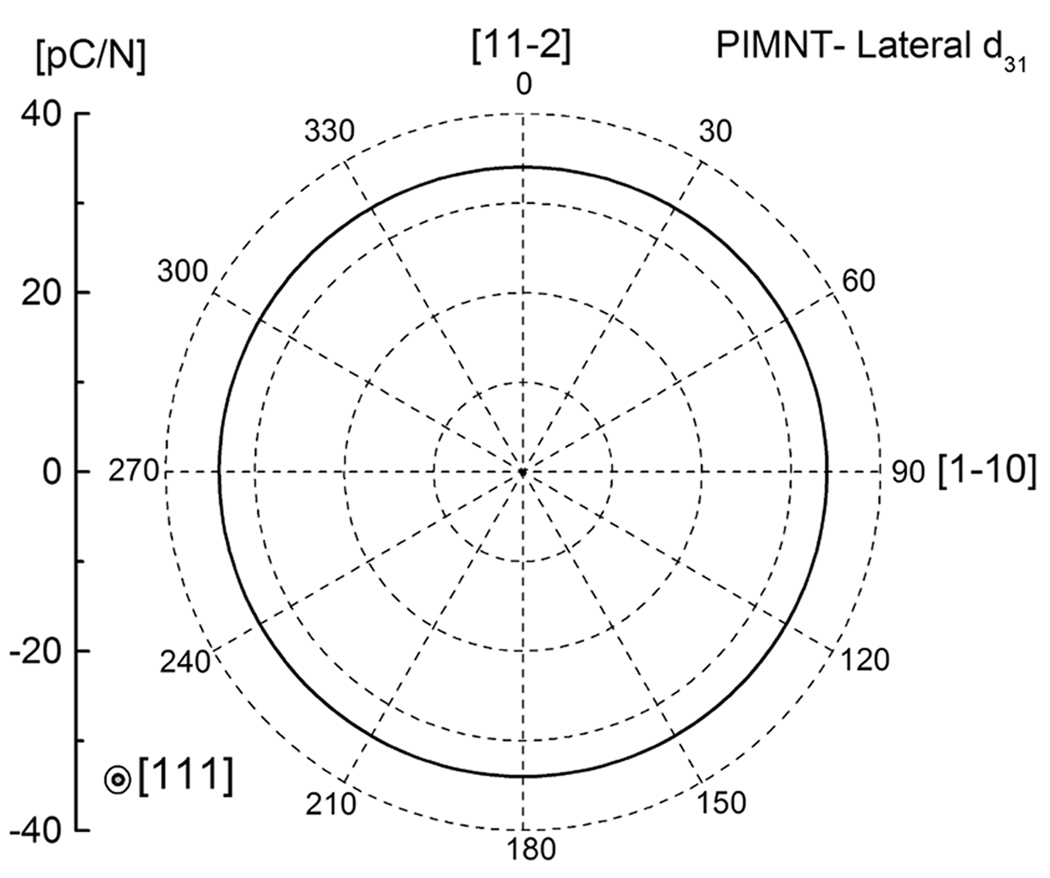
It is worth to mention here that the lateral piezoelectric coefficient d31 in <111> poled crystals (3m symmetry) follows the same trend as that observed in <001> poled crystals (4mm), as shown in Fig. 7. The values of d31 were found to be on the same order along different lateral directions, so no piezoelectric strain incompatability occurs. Thus, the ferroelectric fatigue reported in <111> oriented crystals was induced by the accumulated charge/defect on domain boundaries, rather than mechanical cracks, which was confirmed by the rejuvenation of the polarization switching in <111> oriented samples20–22.
Fig. 7.
Lateral piezoelectric coefficient map for <111> poled crystals.
Different from the studied PIN-PMN-PT crystals, field-induced cracks were also observed in <001> oriented PMNT crystals24–28. The domain size of PMNT crystals with MPB compositions was found to be on the order of 10–30 microns37, while the domain size of the studied PIN-PMN-PT crystals was found to be <1 micron, as shown in Fig. 4a. Thus, the domain wall density in PIN-PMN-PT crystals was much greater than that in PMNT crystals, indicating that the density of the agglomerated defects/charges on the domain boundaries was much higher in PMNT crystals even though the total content of defects on domain boundaries was similar in both crystals. Furthermore, the large domain size in PMNT crystals make it harder to be switched due to clamping effects arising from a higher density of agglomerated defects/charges, which will cause higher accumulation of incompatible piezoelectric strains during the electric field cycling, leading to the crack and fatigue. However, in the same PMNT crystal system, the <110> oriented crystals show much higher crack propagation than that of a <001> oriented crystals28, due to the strong anisotropic lateral piezoelectric activity, as shown in Fig.6.
4.4 Phase transition
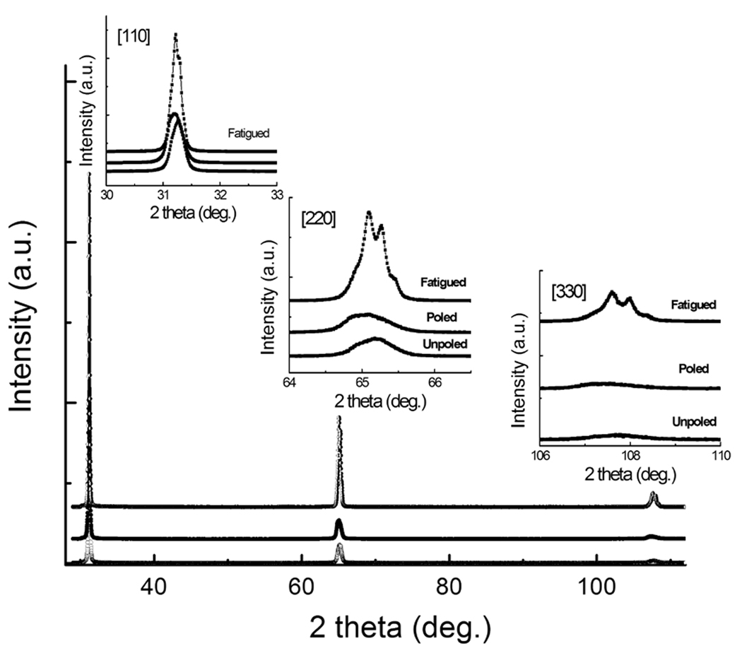
Beside the cracks, phase transitions may also play an important role for the fatigue behavior in <110> oriented crystals. As reported in <110> oriented PMNT crystals, a near completely reversible transformation between rhombohedral to orthorhombic phase occurs at lower electric field than for those oriented along <001> direction38. Furthermore, significant accumulation of residual stress during fatigue measurement will induce the phase transition, which in turn, will cause cracking of <110> oriented crystals more easily when compared to the <001> direction. Thus, in PIN-PMN-PT crystals studied in this work, the applied electric field of < 15kV/cm along <110> direction is expected to induce the orthorhombic phase in the fatigued samples. Fig. 8 gives the XRD pattern, which was performed on the virgin, poled and fatigued <110> oriented sample surface, respectively. It was observed that the <110>, <220> and <330> peaks broadened after the poling process, due to the stress inside the crystals, induced by the poling. Of particular interest is that the peaks were found to be split after the fatigue measurement and were confirmed to be in orthorhombic phase. According to the switching-induced charge-injection model1, the local rhombohedral to orthorhombic phase transformation will cause fatigue (polarization degradation) due to its low dielectric permittivity of orthorhombic crystal, usually being on the order of 500–1000, when compared to rhombohedral counterpart (>4000).
Fig. 8.
XRD patterns for <110> oriented crystals (virgin, poled and fatigued samples).
V. Conclusion
Ferroelectric fatigue in PIN-PMN-PT single crystals was investigated with respect to the crystallographic direction, amplitude of the applied field and acceptor modification. The crystals show strong anisotropic fatigue behavior, where <001> oriented samples exhibit fatigue resistant characteristic, while <110> and <111> oriented samples show a strong ferroelectric fatigue. The Mn- doped crystals were found to possess improved fatigue behavior, due to its high coercive field. It is clear that several different mechanisms account for the ferroelectric fatigue in the crystals. Which one of these mechanisms dominates depends on the microstructure, anisotropic engineered domain and domain size, etc. The fatigue in <111> oriented samples is mainly due to the accumulated defect/charge on the domain boundaries, clamping the domain wall motion, which can be rejuvenated by annealing, while the mechanical failure (cracks) and the phase transition play important roles in the fatigue behavior of <110> oriented samples. The crack development in <110> oriented crystals is mainly attributed to the incompatible strain around the non-180° domain boundaries and the large anisotropic piezoelectric strain/displacement, especially under cyclic field condition. Furthermore, the small domain size in <001> oriented PIN-PMN-PT crystals will benefit the fatigue resistant behavior, while its binary counterpart PMNT with MPB compositions and large domain size suffer from the fatigue due to the microcracks.
Acknowledgment
The work was supported by NIH under Grant No. P41-EB21820 and ONR under grant numbers N00014-07-C-0858 and N00014-09-1-0456. The author (F. Li) wants to thank the support from China Scholarship Council.
Footnotes
Publisher's Disclaimer: This is a PDF file of an unedited manuscript that has been accepted for publication. As a service to our customers we are providing this early version of the manuscript. The manuscript will undergo copyediting, typesetting, and review of the resulting proof before it is published in its final citable form. Please note that during the production process errors may be discovered which could affect the content, and all legal disclaimers that apply to the journal pertain.
References
- 1.Lou XJ. J. Appl. Phys. 2009;105:024101. [Google Scholar]
- 2.Lupascu DC. Fatigue in ferroelectric ceramics and related issues. New York: Springer; 2004. [Google Scholar]
- 3.Scott JF. Ferroelectric Memories. New York: Springer; 2000. [DOI] [PubMed] [Google Scholar]
- 4.Lou XJ, Zhang M, Redfern SAT, Scott JF. Phys. Rev. Lett. 2006;97:177601. doi: 10.1103/PhysRevLett.97.177601. [DOI] [PubMed] [Google Scholar]
- 5.Lou XJ, Zhang M, Redfern SAT, Scott JF. Phys. Rev. B. 2007;75:224104. [Google Scholar]
- 6.Lupascu DC. Solid State Ionics. 2006;177:3161. [Google Scholar]
- 7.Lou XJ. Appl. Phys. Lett. 2009;94:072901. [Google Scholar]
- 8.Zhang SJ, Xia R, Hao H, Liu HX, Shrout TR. Appl. Phys. Lett. 2008;92:152904. doi: 10.1063/1.2908960. [DOI] [PMC free article] [PubMed] [Google Scholar]
- 9.Shvartsman VV, Kholkin AL, Verdier C, Yong Z, Lupascu DC. J. Europ. Ceram. Soc. 2005;25:2559. [Google Scholar]
- 10.Wang D, Fotinich Y, Carman GP. J. Appl. Phys. 1998;83:5342. [Google Scholar]
- 11.Jiang QY, Cao WW, Cross LE. J. Am. Ceram. Soc. 1994;77:211. [Google Scholar]
- 12.Menou N, Muller Ch, Baturin I, Shur V, Hodeau J. J. Appl. Phys. 2005;97:064108. [Google Scholar]
- 13.Liu M, Hsia KJ. Appl. Phys. Lett. 2003;83:3978. [Google Scholar]
- 14.Liu D, Wang C, Zhang H, Li J, Zhao L, Bai C. Surf. and interface analy. 2001;32:27. [Google Scholar]
- 15.Priya S, Kim HW, Ryu J, Uchino K. Appl. Phys. Lett. 2002;80:1625. [Google Scholar]
- 16.Khachaturyan K. J. Appl. Phys. 1995;77:6449. [Google Scholar]
- 17.Yang F, Tang MH, Zhou YG, Liu F, Ma Y, Zheng XJ, Tang JX. Appl. Phys. Lett. 2008;92:022908. [Google Scholar]
- 18.Furuta A, Uchino K. J. Am. Ceram. Soc. 1993;76:1615. [Google Scholar]
- 19.Lee JK, Yi JY, Hong KS. J. Appl. Phys. 2004;96:7471. [Google Scholar]
- 20.Ozgul M, Takemura K, Trolier-McKinstry S, Randall CA. J. Appl. Phys. 2001;89:5100. [Google Scholar]
- 21.Takemura K, Ozgul M, Bornand V, Trolier-McKinstry S, Randall CA. J. Appl. Phys. 2000;88:7272. [Google Scholar]
- 22.Ozgul M, Trolier-McKinstry S, Randall CA. J. Appl. Phys. 2004;95:4296. [Google Scholar]
- 23.Priya S, Kim H, Ryu J, Zhang S, Shrout T, Uchino K. J. Appl. Phys. 2002;92:3923. [Google Scholar]
- 24.Xu Z, Tan X, Han P, Shang JK. Appl. Phys. Lett. 2000;76:3732. [Google Scholar]
- 25.Tan X, Xu Z, Shang JK, Han P. Appl. Phys. Lett. 2000;77:1529. [Google Scholar]
- 26.Fang F, Yang W, Zhang FC, Qing H. Appl. Phys. Lett. 2007;91:081903. [Google Scholar]
- 27.Fang F, Yang W, Luo X. J. Appl. Phys. 2009;106:094107. [Google Scholar]
- 28.Fang F, Yang W, Zhang FC, Qing H. J. Mater. Res. 2008;23:3387. [Google Scholar]
- 29.Zhang SJ, Luo J, Hackenberger W, Shrout TR. J. Appl. Phys. 2008;104:064106. doi: 10.1063/1.2978333. [DOI] [PMC free article] [PubMed] [Google Scholar]
- 30.Zhang SJ, Luo J, Hackenberger W, Sherlock NP, Meyer RJ, Jr, Shrout TR. J. Appl. Phys. 2009;105:104506. doi: 10.1063/1.3131622. [DOI] [PMC free article] [PubMed] [Google Scholar]
- 31.Liu XZ, Zhang SJ, Luo J, Shrout TR, Cao WW. J. Appl. Phys. 2009;106:074112. doi: 10.1063/1.3243169. [DOI] [PMC free article] [PubMed] [Google Scholar]
- 32.Xu GS, Chen K, Yang DF, Li JB. Appl. Phys. Lett. 2007;90:032901. [Google Scholar]
- 33.Tian J, Han PD, Huang XL, Pan HX. Appl. Phys. Lett. 2007;91:222903. [Google Scholar]
- 34.Davis M, Damjanovic D, Hayem D, Setter N. J. Appl. Phys. 2005;98:014102. [Google Scholar]
- 35.Wang XS, Wang CL, Zhong WL, Tilley DR. Solid State Commun. 2002;121:111. [Google Scholar]
- 36.Kumazawa T, Kumagai Y, Miura H, Kitano M, Kushida K. Appl. Phys. Lett. 1998;72:608. [Google Scholar]
- 37.Fang F, Luo X, Yang W. Phys. Rev. B. 2009;79:174118. [Google Scholar]
- 38.Viehland D, Li JF. J. Appl. Phys. 2002;92:7690. [Google Scholar]


