Abstract
Lie group symmetry in a mechanical system can lead to a dimensional reduction in its dynamical equations. Typically, the symmetries that one exploits are intrinsic to the mechanical system at hand, e.g. invariance of the system’s Lagrangian to some group of motions. In the present work we consider symmetries that arise from an extrinsic control task, rather than the intrinsic structure of configuration space, constraints, or system dynamics. We illustrate this technique with several examples. In the examples, the reduction enables us to design essentially global feedback controllers on the reduced systems.
We apply task-induced symmetry and reduction to a recently developed 6 DOF kinematic model of steerable bevel-tip needles. The resulting controllers cause the needle tip to track a subspace of its configuration space. We envision that the methodology presented in this paper will form the basis for a new planning and control framework for needle steering.
I. INTRODUCTION
Consider the motion of a simple cart in a plane, described by the usual kinematic equations of motion (i.e. ẋ = υ cos θ, ẏ = υ sin θ, θ̇ = ω). Suppose we are interested in making the cart follow a line, for example the x-axis. There is a natural symmetry induced by the task: any motion along the x-axis does not affect the control task. Hence to follow the x-axis, we only need to consider two of the three states and their dynamics, namely ẏ = υ sin θ, θ̇ = ω. In this trivial example, reduction results from an extrinsic, “user-defined” control task, rather than an intrinsic property of the system itself.
For the trivial example above, it is not clear if a similar reduction would be possible if the goal were to follow some other shape, such as, say, a circle, or if the kinematics were more complicated. In the following sections we present a general framework in which to answer these questions and then illustrate the approach with several examples on SE(2) and SE(3) that culminate in a novel approach to the control of steerable needles, which was the principal motivation for us to study this problem. Our approach involves two simple ingredients. First, for simplicity and since the primary motivation for the present work is needle steering which has been modeled as a kinematic system, we consider kinematic systems on Lie groups. Second, the task should be described as the zero of a “task functional” on the group. With these ingredients, the subgroup of configuration space to which the task is invariant is used to reduce the kinematic equations of motion.
In previous work on mechanical systems reduction has been used when the dynamics of the system exhibit some intrinsic symmetry. If the Lagrangian of a mechanical system is invariant to the action of a Lie group, then such a system is said to exhibit symmetry and the Lie group is known as the symmetry group. In unconstrained systems with symmetry, mechanical connections as defined in [11] can be used for reduction. Bloch et al. [4] define a nonholonomic connection as a combination of mechanical and Ehresmann connections and use it to perform Lagrangian reduction in the presence of nonholonomic constraints. Ostrowski [13] uses these connections to reduce the systems whose configuration spaces are a direct product of the symmetry group (also called the fiber) and a manifold called a shape space (also called the base space).
The work we present in this paper is closely related to the literature on relative equilibria [5], [8] however the systems we consider in this paper are kinematic systems. Roughly speaking, given a Hamiltonian system with symmetry, a relative equilibrium is a trajectory that is an equilibrium of the reduced system. However, our primary system of interest in the present work, needle steering, is inherently highly symmetric; in fact, the needle evolves according to a left-invariant vector field on SE(3), rendering SE(3) itself the intrinsic symmetry group! That observation itself does not prove particularly useful from a design point of view, so we introduce tasks that actually break some of the symmetry. Then, the “left over” symmetry enables task-specific reduction and leads us, at least in the specific examples presented, to an essentially global control strategy to achieve the task.
II. GENERAL FRAMEWORK
Let G be a Lie group.1 Consider the left-invariant kinematic system
| (1) |
where g = g(t) ∈ G is the configuration to be controlled, ξi ∈ 𝔤 are constant vectors in the Lie algebra of G, k is the total number of scalar inputs to the system and ui’s for i = 1, 2, ‥k are inputs to the system. We consider cases where the control task is encoded as the zero value of a functional φ : G → ℝ defined on the configuration space. Let H be the subgroup2 of G invariant to the task, namely
| (2) |
Our goal is to find a (feedback) controller u such that φ(g(t)) → 0 asymptotically.
Intuitively, we ignore motions in the space H, since such motions get us no closer to or further from our goal of bringing φ(g) to zero. In effect, we perform control only in the space B that is “left over” after ignoring H. Since B is of lower dimension than G (dim B = dim G−dim H), the kinematics (1) and task functional φ likely have a simpler form on B than on G. In fact, in the examples that follow, the task functional reduces to a candidate Lyapunov function.
Formally, we use H and G to construct a fiber bundle (see Appendix). Since H is a subgroup of G there exists a bundle projection π : G → B := G/H. Since H does not affect the control task, we consider the state evolution only in the base space. We use r to represent coordinates for the base space B and h for those in the fiber H. Since the vector field in (1) is G invariant and H is a subgroup of G, the vector field is also H invariant. This results in a well defined vector field on B that does not depend on H. The vector field on B can be calculated as
| (3) |
where fi(r) = Tπ · gξi. This is the reduced kinematic equation on the base space B.
For completeness, we derive the kinematic equation for the fiber variable h ∈ H. Though one can employ the concept of connections for a global derivation, we content ourselves with the derivation in local coordinates.3 Consider a local section s : U ⊂ B → G. Recall that by definition, a local section s satisfies π ○ s = IdU4. This section, s, induces the local trivialization which is a local diffeomorphism defined by the map:
Its inverse ψ−1 : π−1(U) → H × U is given by ψ−1(g) = (g · (s(π(g)))−1, π(g)). From the definition of ψ we can rewrite g−1ġ as
This results in
| (4) |
which also depends only on r and u. The equation for the fiber variable h in (4) is sometimes called the reconstruction equation [10]. The above construction can be summarized in a commutative diagram:
 |
We illustrate this reduction method by applying it to the tasks of following lines and circles with a planar cart. Then, we tackle the problem of steering flexible bevel-tip needles to follow spheres and planes in ℝ3.
III. FOLLOWING CURVES WITH A PLANAR CART
In this section we revisit the motivating example from Section I and apply the above reduction framework. We then show how this can be applied to a more interesting problem of following a circle. These toy problems are useful because they have similar (but simpler) structure to that of the needle steering problems discussed in Section IV.
Consider a body reference frame attached to the cart at (x, y) with the frame x-axis pointing along the forward translational velocity of the cart. The configuration space G is the group of transformations in 2D, namely G = SE(2) ≅ SO(2)Ⓢℝ2 ≅ S1Ⓢℝ2. To denote an element g ∈ SE(2), we use both g = (R, p) ∈ SO(2)Ⓢℝ2 and its homogeneous representation
| (5) |
The kinematic equation of the unicycle can be written as
| (6) |
In this case the configuration space G is the special Euclidean group in two dimensions i.e. G = SE(2). We now consider two control tasks: following a line and following a circle.
A. Straight Line Following
To follow the x-axis, the cart’s position should be such that it is oriented parallel to the x-axis and its y-coordinate should be zero. This is precisely the example discussed in the introduction, and as shown, is trivial in local coordinates on SE(2); because of its simplicity, it may seem that the machinery in this paper is more complicated than needed, but the example serves to illustrate the general framework in detail.
For the case when the cart is following the x-axis in the positive direction, this task can be defined as a zero of the function φ defined as
where ei’s for i = 1, 2 are principal unit vectors in two dimensions. When the cart is following the x-axis in the negative direction, this task can be defined as a zero of the function, .
The function φ is invariant to translations along the x-axis of the world frame. Hence given this control task, the symmetry group is
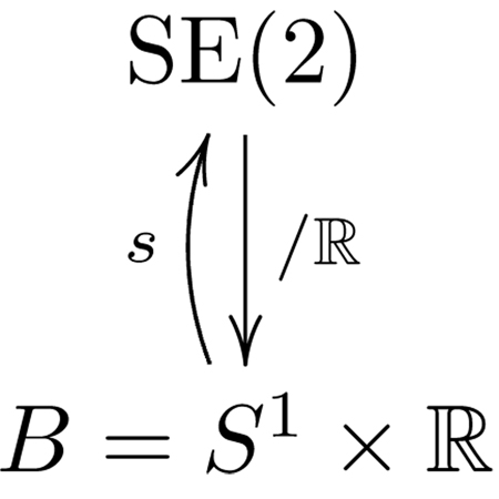
Let B := G/H ≅ S1 × ℝ. Define the projection map, π : G → B by
For all h ∈ H, . Therefore, π is H invariant. Also, if g1 ∈ π−1(r) then g2 = hg1 ∈ π−1 (r), ∀h ∈ H. Therefore π−1 (r) ≅ H for each r ∈ G/H. Let r = [r1, r2, r3]T denote an element in B with . Define a global section s : B = S1 × ℝ → SE(2) by
Note that π ○ s = IdB. Hence, the projection π : SE(2) → S1 × ℝ is a trivial bundle. With this section, a global diffeomorphism ψ : H × B ≅ ℝ × (S1 × ℝ) → SE(2) can be constructed by ψ(h, r) = hs(r). This fiber bundle can be represented by the following diagram:
 |
Assuming that the forward velocity of the cart, υ, is held constant at υ = 1, the dynamics in the reduced space can be calculated as:
| (7) |
with a holonomic constraint given by . The reconstruction equation for the fiber variable h = x is given by
| (8) |
Observe that R−1 e1 is the vector e1 seen in the body reference frame. If the cart is following the x-axis, r = [±1, 0, 0]T depending on whether the cart is following the line along the positive or negative x-axis. We claim that choosing the following control input will result in the cart following the desired line:
| (9) |
We use the task function reduced to the base space as a candidate Lyapunov function, . The time derivative of φ, upon plugging (9), is which is negative semi-definite. Each level set Ωc = {r ∈ B : φ(r) ≤ c}, c > 0 is positive invariant. The subset where φ̇ = 0 is given by E = {r ∈ S1 × ℝ : r2 = 0} ⊂ Ωc. The largest invariant subset in E contains only the points r = [0,±1, 0]T. Therefore from LaSalle’s invariance principle, we conclude that the cart follows the desired line. Further by considering the local chart (r2, r3) and by eigen-value analysis we can see that the equilibrium point r = [0, 1, 0]T is stable and the other one is a saddle. To follow the line in the other direction, simply let ω = r3 − kr2 for some k ∈ ℝ+.
B. Circle Following
Suppose we are interested in making the cart follow a circle given by X = {(x, y) ∈ ℝ2 | x2 + y2 − ρ2 = 0}. This task can also be described as the zero of the function, φ defined by:
One can show that H = {g = (R, p) : p = 0} ≃ SO(2) ⊂ SE(2) is the largest subgroup that leaves φ invariant. Construct a fiber-bundle π : SE(2) → SE(2)/SO(2) by
Notice that B := SE(2)/SO(2) ≅ ℝ2. If we introduce a global section s : ℝ2 → SE(2) by
for r ∈ ℛ, then we can see that π defines a trivial bundle. Let r = [r1, r2]T. Assuming that the forward velocity of the cart is constant (say, υ = 1), the reduced space dynamics are given by
| (10) |
and the fiber variable θ satisfies
| (11) |
Observe that r = R−1p is the vector from the center of the desired circle to the origin of the body frame, written in the body frame. This implies that if the cart is following the desired circle clockwise r = [0, ρ]T, and r = [0,−ρ]T if it is following the desired circle counter-clockwise. We show that choosing the following control input will result in the cart following the desired circle clockwise:
| (12) |
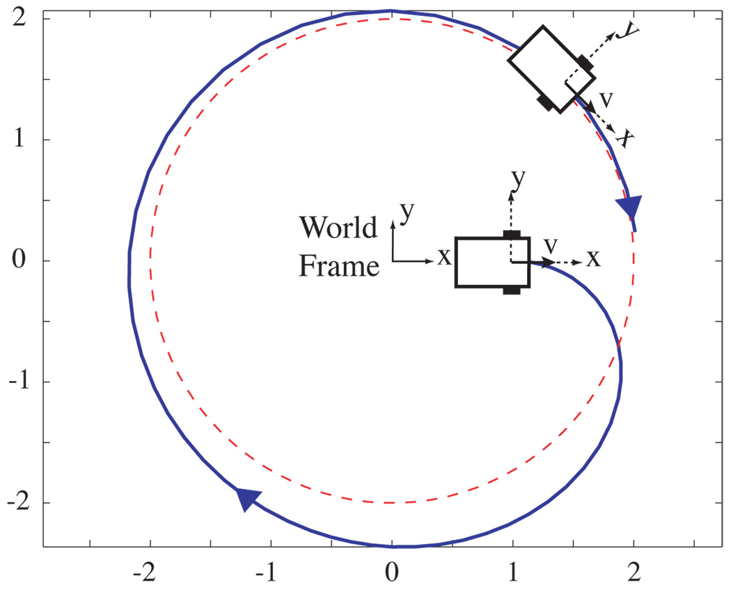
Again we use the task function (restricted to the base space) as a candidate Lyapunov function, namely . Then the time derivative of the Lyapunov function is . We note that φ̇(r) is negative semi-definite and that the invariant subset of the set where φ̇(r) = 0 consists of only r = [0, ρ]T. As before, one can show using LaSalle’s invariance principle that the cart follows the desired circle clockwise. Figure 1 is a simulation of the circular wall-following in a cart. The cart is initially away from the desired circle but, it asymptotically follows the desired circle. If it is desired to follow the circle counter-clockwise, choose the input as . Note here that convergence is global.
Fig. 1.
Cart following a circle: Red dotted circle is the desired circle to be followed by the cart. Initially the cart is away from the desired circle but with the application of the controller, it follows the circle.
IV. APPLICATIONS TO NEEDLE STEERING
Long thin needles are used to perform percutaneous therapies in many diagnostic and therapeutic procedures. It has been shown that flexible bevel-tip needles have better maneuverability than rigid symmetric needles and thus improve the physicians’ performance [6], [14]. A flexible bevel-tip needle can be steered by rotation and insertion at the base of the needle (outside the patient). During insertion, the asymmetry of the bevel creates a moment at the needle tip, deflecting the needle and causing it to follow a circular arc. As the needle is rotated, the bevel tip is reoriented in space, so that subsequent insertion follows an arc in a new plane.
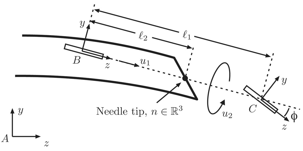
We use the kinematic model developed by Webster et al. [14] for a bevel tip flexible needle. It is modeled as a generalisation of the nonholonomic bicycle model, and neglects torsional compliance of the needle shaft (Figure 2). In this model, ℓ1, ℓ2 determine the location of bicycle wheels with respect to the needle tip. Parameter ϕ is the fixed front wheel angle relative to the rear wheel. Frame A is the inertial world reference frame and frames B and C are attached to the two wheels of the bicycle. In homogeneous coordinates, the rigid body transformation between frames A and B is given by the rigid body transformation matrix:
| (13) |
Webster et al. obtain a kinematic model for needle steering:
where υ is the insertion speed, ω is the rotation speed of the needle, and the control vector fields are given by .
Fig. 2.
Needle steering kinematic model: Frame A is the inertial world reference frame. Frames B and C are attached to the two wheels of the bicycle. This figure is reproduced from [14] with permission from the authors.
If the needle is inserted into the tissue without any rotation at the base, it stays in a 2D plane within the tissue. The location of the 2D plane depends on the initial insertion conditions of the needle into the tissue. Also, in the 2D plane the needle follows a circle of curvature κ = tan ϕ/ℓ1.
A. Motivation: Path Planning on Subsurface Patches
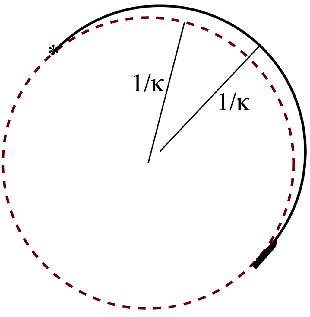
The high degree of nonholonomy for needle steering (four [14]) renders global feedback control to a point in SE(3) challenging, and likely impossible in practice. One possible solution is to plan a path in SE(3) and execute feedback control to follow the path. However, feasible paths are not necessarily asymptotically trackable. In fact, following the natural trajectory of the system, a circle of radius 1/κ, is not small-time locally trackable, in the sense that there exist arbitrarily small perturbations cannot be driven back to the desired trajectory in an arbitrarily small amount of time. To see this, refer to Figure 3.
Fig. 3.
Small-time local controllability fails even for tracking a natural trajectory of the needle, a circle (green, dashed) of radius 1/κ. Here, a small initial perturbation in heading of the needle (black, solid) is depicted. The radius of curvature of the actual needle trajectory can never be less than 1/κ, and thus even for the smallest possible perturbation of the needle heading, the needle must travel at least π/κ before re-intersecting (*) the desired path. Pitching out of the plane of the circle only exacerbates this issue, and the problem cannot be overcome with control or replanning.
There are several potential ways to overcome this problem. One could plan paths whose radius of curvature is always greater than 1/κ. We suspect such curves can be followed arbitrarily closely (if not exactly), although the high degree of nonholonomy of the system may render this challenging.
An alternative approach would be to develop low-level controllers that cooperate with the 2D planners by Alterovitz et al. [1], [2]. Their planner, which relies on the needle staying within a specified 2D plane, constructs a sequence of circular arcs of radius 1/κ that can be achieved via alternating insertions and 180° rotations of the needle shaft. A real-time replanner corrects for within plane deviations from the desired piecewise circular path. In the prior work, Kallem and Cowan [9] designed and implemented in simulation and laboratory experiments an observer-controller pair that steers a needle to stay within a desired 2D plane. In effect, this low-level 2D plane-following controller ensures that the needle remains close to a desired 2D plane, on top of which Alterovitz et al.’s planner can operate.
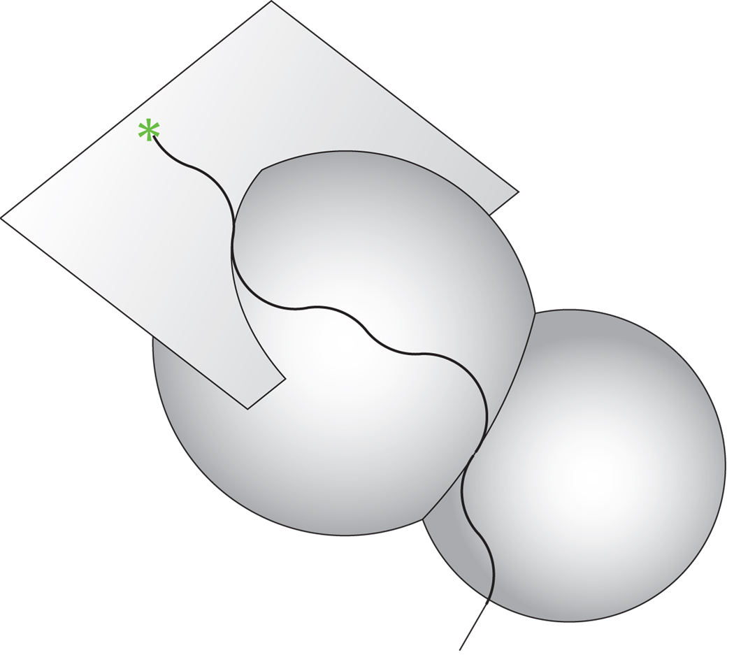
Our long-term research will generalize this real-time replanning and low-level control architecture, as depicted in Figure 4. We envision a “subspace planner” that chooses feasible subspaces, upon which an Alterovitz-style planner [1] builds paths within each subspace.
Fig. 4.
A stylized depiction of a needle trajectory that remains within a sequence of 2D patches. The plane-following controller was reported in [9], and the sphere-following problem is reported in this paper (Section IV-C).
It is important to understand how the planning and control architecture relates to the methodology outlined in Section II. In needle steering, the entire space G is all of SE(3) – positions and orientations of the needle tip in the tissue. The space in which the planner acts – that is, motions within a surface – is the symmetry group, or fiber, that defines the projection from the entire space into the base space. The base space is where the low-level controller operates in an effort to drive the needle back to the desired surface.
The prior work by Kallem and Cowan [9] used local coordinates to parameterize the configuration space (SE(3)), and performed a coordinate-based reduction “by hand” by noting that the three configuration variables central to the control task evolved independently of the others. Here, we apply the general framework developed in Section II for two additional tasks.
B. Controlling the Needle Tip to a Plane Parallel to a Desired 2D Plane
Without any loss of generality, let the desired plane be the y − z plane. The configuration space, G is SE(3). The control task is to stabilize the needle tip to a plane parallel to the y−z plane. In other words, it is desired that the circle the needle tip traces at steady state, during insertion without any rotation at the base be parallel, to the y − z plane. The task can be described by a surface X ⊂ SE(3) given by
The task can also be described as the zero of the function, φ defined as:
where g ∈ SE(3) is represented as in (13) and ei’s for i = 1, 2, 3 are the principal unit vectors in three dimensions. This form of the function φ is for the cases when the needle tip in steady state undergoes rotation about the positive x-axis. In the case when the needle tip undergoes rotation about the negative x-axis, the function, φ can be defined as .
Note that X is also a subgroup of G = SE(3). Hence the symmetry group is
The symmetry group, H, can be thought of as a combination of 2D transformations in the y − z plane and translations along the x-axis relative to the world frame. With these group definitions, B := G/H = S2. Define a projection map from G to B as
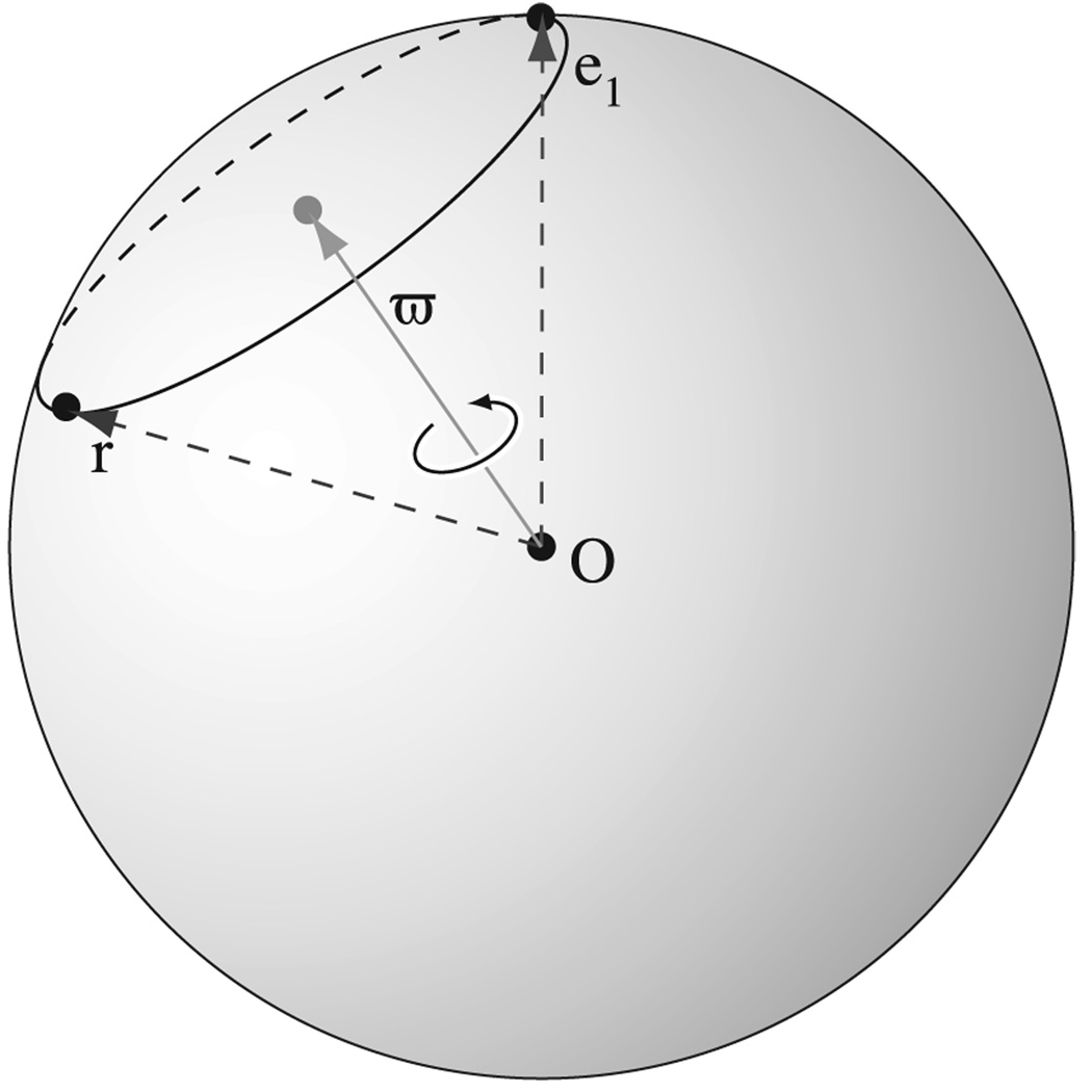
Choose an open subset U of B as the unit sphere excluding the (−1, 0, 0) point. That is U = S2 − {(−1, 0, 0)}. Define the bundle section on U, s : U → π−1 (U) ⊂ G as
where . This section can be seen in Figure 5. With this section, locally g ∈ G can be expressed as g = hs(r) ≃ (h, r), where h ∈ H and r ∈ B. To completely cover S2 consider U′ = (S2 − {(1, 0, 0)}) and a similar section can be constructed. These make the map π a fiber bundle which can be summarized by the following commutative diagram:
 |
Fig. 5.
Illustration of the Bundle Section: Unit vector ϖ bisects r and e1. If the r is rotated about ϖ as axis by π then it coincides with e1. The circle through the points r and (1, 0, 0) is a latitude of S2 drawn perpendicular to ϖ.
We assume that the insertion speed is held constant at υ = 1. This assumption is equivalent to parameterization of the system with the length of the needle inserted in to the tissue (when the insertion speed is not zero). Base space elements can be written in coordinates as r = [r1, r2, r3]T ∈ ℝ3 with . The dynamics of the base space can be calculated as:
| (14) |
The fiber variable h = (eê1θ, p) ∈ H satisfies
| (15) |
where s̄(r) = eϖ̂(r)π.
For the task to be completed, the state in the reduced system should be r = [±1, 0, 0]T. Choosing the following control input we show that the task is achieved:
| (16) |
Once again, we use the task function in base coordinates as a candidate Lyapunov function, namely φ(r) = 1 − r1. The time derivative of the Lyapunov function is which is negative semi-definite in r. The set where φ̇ = 0 is given by E = {r = [r1, r2, r3]T ∈ S2|r2 = 0}. The largest invariant set in E contains only the points r = [±1, 0, 0]T. Hence, from LaSalle’s invariance principle, we can conclude that needle tip can be stabilized to a plane parallel to the desired plane. Notice that asymptotically the fiber dynamics become
This shows us that the fiber variables trace a circle of radius 1/κ, which we knew from the needle steering model. Further by considering the local chart (r2, r3) and by eigen-value analysis we can see that the equilibrium point r = [1, 0, 0]T (corresponding to the needle tip tracing a circle of radius 1/κ parallel to the y − z plane counter clockwise) is stable, and the other equilibrium point unstable. For the needle tip to trace the circle clockwise, let ω = −kr2 for some k ∈ ℝ+.
C. Controlling the Needle Tip to a Spherical Surface
In this section we use the reduction technique developed in II to control the needle tip to the surface of a sphere with radius ρ > 1/κ. If the needle tip stays on the surface of the desired sphere at steady state it has to follow a circle of radius ϱ = 1/κ. Let . If the needle is staying on the desired circle on the sphere, the position vector of the center of the sphere written in the body frame is given by R−1p. This must be [−d, ϱ, 0]T or [d, ϱ, 0]T depending on which direction the needle tip is following the circle of radius ϱ.
In this example, the control task can also be described as the zero of the function
or
depending on the direction the needle tip follows the circle. It is easy to see that H = SO(3) leaves the function, φ, invariant. Hence, the symmetry group, H for this control task is SO(3). The base space, B := G/H = ℝ3. The bundle projection π : SE(3) → ℝ3 is given by
where g = (R, p) ∈ SO(3)Ⓢℝ3 ≅ SE(3). This bundle is trivial because we can construct a global section s : ℝ3 → SE(3) as
Given (R, r) ∈ H × B = SO(3) × ℝ3, the corresponding g ∈ SE(3) can be calculated as . Assuming υ = 1, the dynamics in the base space can be written as
| (17) |
and the fiber variable R ∈ H = SO(3) satisfies
| (18) |
The control input
| (19) |
makes the reduced space converge to r = [−d, ϱ, 0]T. Consider the reduced task functional as the candidate Lyapunov function: . Its time derivate, φ̇(r) = ω(dr2 + ϱr1) = −(dr2 + ϱr1)2, is negative semi-definite. The invariant subset of the set where φ̇(r) = 0 contains only r = [−d, ϱ, 0]T. Again using LaSalle’s invariance principle we can conclude that the needle tip stays on the surface of the desired sphere. To follow the circle in the desired sphere in the other direction, choose ω = dr2 − ϱr1.
V. CONCLUSIONS
We developed a general framework to perform task-specific reduction in kinematic systems on Lie groups. We applied this method to a two systems, a planar cart (as an illustrative example) and flexible bevel-tip needle steering with configuration spaces SE(2) and SE(3) respectively. In the examples, the reduction enabled us to design essentially global feedback controllers on the reduced systems. Also, the task functional became a Lyapunov function in reduced coordinates. We envision that the methodology presented in this paper will form the basis for a new planning and control framework for needle steering.
This paper considered only kinematic systems, but we believe our results can be used along with reduction techniques for mechanical systems (e.g. [13]) to perform a two-stage reduction. In the first stage, mechanics-based “intrinsic” reduction can separate the configuration space into a shape space and a symmetry (Lie) group. The dynamics on the shape space can be obtained from the so-called reduced Lagrangian, while a reconstruction equation generates motions in the symmetry group. This reconstruction equation takes the place of the Lie group kinematics (1) in this paper. Certain control tasks may enable us to perform a second “extrinsic” (task-specific) reduction, thus further decomposing the symmetry group into a base and fiber, as described in this paper.
ACKNOWLEDGEMENTS
This work was supported in part by the National Institutes of Health grant R21-EB003452. Jusuk Lee provided critical review of this manuscript.
APPENDIX
A. Lie Groups
A Lie group, is essentially a smooth group which is also a smooth manifold. The groups discussed in this paper in detail are the Euclidean groups SE(2) = SO(2)Ⓢℝ2 and SE(3) = SO(3)Ⓢℝ3. The symbol Ⓢ denotes semi-direct product. If R1,R2 ∈ SO(2) and p1, p2 ∈ ℝ2, the product in the group obtained by semi-direct product of SO(2) and ℝ2 is given by (R1, p1) * (R2, p2) = (R1R2,R1p2 + p1). Note that as sets, SE(2) = SO(2) × ℝ2 but as groups, SE(2) = SO(2)Ⓢℝ2.
We identify the tangent space TSE(3) of the Lie group SE(3) with
| (20) |
where 𝔰𝔢(3) is the Lie algebra of SE(3). The “wedge/hat” isomorphism ℝ3 ≃ 𝔰𝔬(3) is defined by
where 𝔰𝔬(3) is the Lie algebra of SO(3). In a standard abuse of notation the wedge/hat isomorphism ℝ3Ⓢℝ3 ≃ 𝔰𝔢(3) relates translational υ and angular ω velocities to “twists” ξ ∈ 𝔰𝔢(3) via
More detail can be found in [12], for example. The identification (20) occurs via left translation, i.e.
| (21) |
where ξ = g−1 ġ, ω = (R−1 Ṙ)∨, and υ = R−1 ṗ.
B. Fiber Bundles
A bundle [7] is a triple (E, π, M) where E and M are differentiable manifolds and the map π : E → M is a continuous map. The space E is called the entire space, M is called the base space and the map π is called the projection map. The inverse image π−1 (x) is called the fiber over x ∈ M. If all the individual fibers π−1 (x), for x ∈ M are diffeomorphic to the common space F, then F is called the fiber of the bundle and such a bundle is referred to as a fiber bundle. Locally, E = M × F; if this relationship is global, the fiber bundle is trivial. A natural bundle structure arises in the case that a group H, called the symmetry group, acts on the entire space, E, in which case M = E/H can be defined as the quotient space, and H is the fiber.
Footnotes
We assume the reader is familiar with notions from Lie group theory as it relates to reduction. The appendix reviews some basic facts about fiber bundles. For more detail, see Bloch [3].
Note that H is a subgroup, since if h1 ∈ H and h2 ∈ H, then for all g ∈ G, we have φ(h1h2g) = φ(h2g) = φ(g) (closure). Moreover, the identity e ∈ G is obviously in H. The inverse of every element in h ∈ H is also in H, since φ(g) = φ(eg) = φ(hh−1 g) = φ(h−1 g).
In the examples that follow, the local chart covers all but a set of measure zero of the base space.
For all r ∈ U, π (s(r)) = r.
Contributor Information
Vinutha Kallem, Department of Mechanical Engineering, Johns Hopkins University, Baltimore, MD 21218 USA (vkallem@jhu.edu)..
Dong Eui Chang, Department of Applied Mathematics, University of Waterloo, Waterloo, ON, N2L 3G1, Canada (dechang@math.uwaterloo.ca)..
Noah J. Cowan, Department of Mechanical Engineering, Johns Hopkins University, Baltimore, MD 21218 USA (ncowan@jhu.edu).
REFERENCES
- 1.Alterovitz R, Goldberg K, Okamura A. Planning for steerable bevel-tip needle insertion through 2D soft tissue with obstacles; IEEE International Conference on Robotics and Automation; 2005. pp. 1652–1657. [Google Scholar]
- 2.Alterovitz R, Lim A, Goldberg K, Chirikjian GS, Okamura AM. Steering flexible needles under markov motion uncertainty; IEEE International Conference on Intelligent Robotics and Systems; 2005. [Google Scholar]
- 3.Bloch A. Nonholonomic Mechanics and Control. volume 24. NY: Springer; 2003. [Google Scholar]
- 4.Bloch A, Krishnaprasad P, Marsden J, Murray R. Nonholonomic mechanical systems with symmetry. Archive for Rational Mechanics and Analysis. 1996;136:21–99. [Google Scholar]
- 5.Bullo F, Lewis AD. Reduction, linearization, and stability of relative equilibria for mechanical systems on Riemannian manifolds. Acta Applicandae Mathematicae. 2007 To appear. [Google Scholar]
- 6.Engh J, Podnar G, Khoo S, Riviere C. Flexible needle steering system for percutaneous access to deep zones of the brain; IEEE Northeast Bioengineering Conference; 2006. [Google Scholar]
- 7.Isham CJ. Modern Differential Geometry for Physicists. World Scientific; 1999. [Google Scholar]
- 8.Jalnapurkar S, Marsden J. Stabilization of relative equilibria. Automatic Control, IEEE Transactions on. 2000;45(8):1483–1491. [Google Scholar]
- 9.Kallem V, Cowan NJ. Image-guided control of flexible bevel-tip needles. IEEE International Conference on Robotics and Automation; April 2007; Rome, Italy. pp. 3015–3020. [DOI] [PMC free article] [PubMed] [Google Scholar]
- 10.Marsden J, Montgomery R, Ratiu T. Reduction, Symmetry and Phases in Mechanics. American Mathematical Society; 1990. [Google Scholar]
- 11.Marsden JE, Ostrowski JP. Symmetries in motion: Geometric foundations of motion control. Nonlinear Science Today. 1998 [Google Scholar]
- 12.Marsden JE, Ratiu TS. Introduction to Mechanics and Symmetry. Springer; 1999. [Google Scholar]
- 13.Ostrowski J. Computing reduced equations for robotic systems with constraints and symmetries. IEEE Transactions on Robotics and Automation. 1999;15(1):111–123. [Google Scholar]
- 14.Webster RJ, Kim JS, Cowan NJ, Chirikjian GS, Okamura AM. Nonholonomic modeling of needle steering. International Journal of Robotics Research. 2006 May/June;25(5/6):509–526. [Google Scholar]


