Abstract
We demonstrate a wide tuning range high-speed wavelength-swept semiconductor laser based on a polygon scanning filter that is common to two laser cavities. Linear wavelength tuning was achieved over 145 nm around 1310 nm at a tuning repetition rate of 20 kHz. The wavelength tuning filter is expandable to accommodate multiple semiconductor optical amplifiers for further widening of the laser wavelength tuning range.
Index Terms: Optical filters, semiconductor lasers, semiconductor optical amplifiers (SOAs), tunable lasers
Wavelength-swept lasers [1]–[4] have attracted great interest as optical sources for various applications such as optical reflectometry [5], [6], biomedical imaging [7]–[10], sensor interrogation [11], and test and measurement [12]. A wide tuning range is required to achieve high axial resolution in optical imaging and wider working wavelength range in sensor interrogation and test and measurement. A widely tuned solid-state laser has been developed to provide 75-nm tuning near 1240 nm at 2-kHz scan rate [6]. Solid-state lasers, however, provide only modest gain and exhibit relaxation oscillation frequencies in the range of tens to hundreds of kilohertz, frustrating efforts toward high-speed tuning. Semiconductor gain elements, by comparison, provide vastly higher gain and, in addition, can be incorporated into compact resonator designs resulting in inexpensive and robust lasers. Recently, a high-speed wavelength-swept laser using a semiconductor optical amplifier (SOA) as a gain medium was demonstrated operating at 15.7-kHz tuning repetition rate with a linewidth on the order of 0.1 nm [3]. This source enabled high-speed optical frequency-domain imaging of biological samples [10]. However, the tuning range of the wavelength-swept laser has been limited especially at such rapid scan rates due to the limited gain bandwidth of individual semiconductor gain materials. Although quantum-dot-based SOAs are emerging to provide very wide gain bandwidths [13], further development is required before they achieve widespread application.
An alternative approach to achieving an increased tuning range relies on the combination of two or more gain media whose gain spectra are distinct. Combined gain media have been utilized for dual-wavelength fiber lasers and high-power solid-state lasers [14], [15]. Additionally, a broad-band amplified spontaneous emission (ASE) source was demonstrated using two edge-emitting light-emitting diodes for improved axial resolution in optical coherence tomography [16], [17]. However, combining gain media for linearly swept continuously tunable lasers has not been demonstrated.
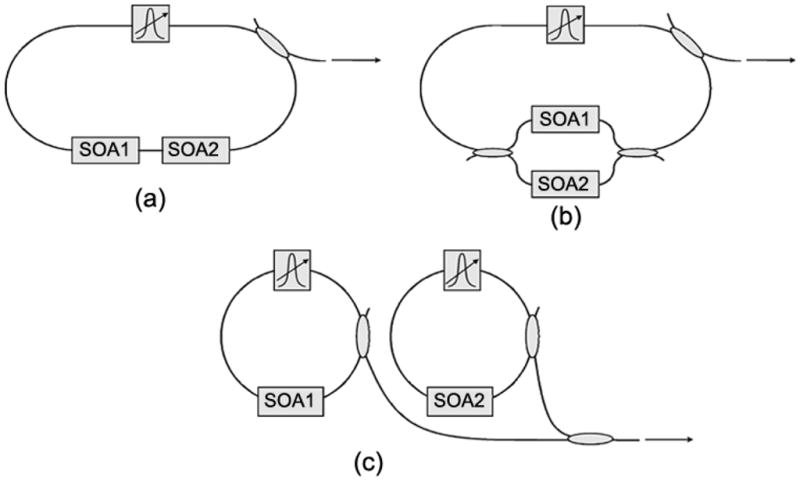
Three different schemes can be considered to combine the spectrally distinct gain regions of multiple SOAs for a wide tuning range wavelength-swept laser. Positioning the SOAs serially in an extended-cavity semiconductor laser, as shown in Fig. 1(a), is problematic since each SOA exhibits absorption in the portion of the spectrum outside of its unique gain band. The parallel configuration of Fig. 1(b) is another possibility. In this configuration, each SOA amplifies independently, so that both SOA amplification bands are fully utilized in the laser. However, the two 50/50 couplers in this configuration introduce an additional 6-dB loss for each light path, reducing the lasing bandwidth. A portion of this loss may be reduced using wavelength-division-multiplexing (WDM) couplers.
Fig. 1.

Schemes for combining two SOAs. (a) Serial configuration, (b) parallel configuration, and (c) two laser cavity configuration.
Another way to increase the wavelength sweep range is to combine independent laser outputs where each laser covers a distinct spectral band, as shown in Fig. 1(c). The challenge of this approach is in synchronizing the wavelength sweep of the independent resonators. The combined laser output should comprise a single spectral band with a narrow instantaneous linewidth and tuning should be continuous across the entire spectrum provided by the two SOAs. In this letter, we describe the use of a novel polygon scanner-based filter as the common element of two laser cavities and demonstrate a linear tuning range of 145 nm.
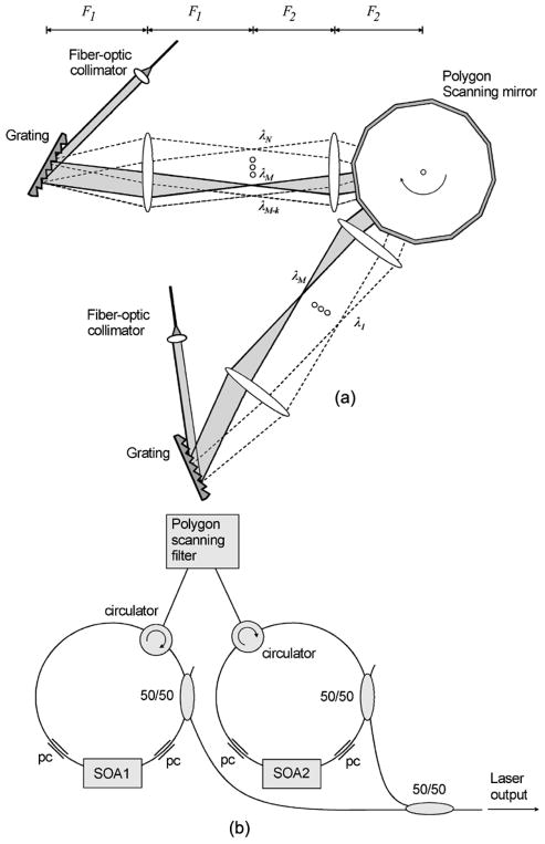
Fig. 2 shows a schematic of the laser. Two SOAs (Kamelian SOA-10-18-N-13R-FA and Philips CQF 882/e) with different center wavelengths performed as gain media in two independent laser cavities. A reflection-type wavelength scanning filter having two input–output ports was incorporated into the laser cavities. The wavelength scanning filter consisted of two identical polygon scanning filters [3] sharing one polygon mirror. The filters were configured such that at each point in time during the rotation of the polygon, the same wavelength component was returned to each SOA and both filters had the same free spectral range (FSR).
Fig. 2.
(a) Schematic of the polygon scanning filter. (b) Schematic of the wavelength-swept laser. PC: Polarization controller.
The parameters of the optical components in the experiment were selected so that the FSR of the filter was slightly wider than the combined gain bandwidth range of the two SOAs. Each filter comprised a blazed diffraction grating with 600 lines/mm, an afocal telescope with two achromatic lenses of F1 = 100 mm and F2 = 60 mm, and a shared polygon scanning mirror with 40 facets, θ = 9° and L = 3.9 mm, where θ denotes the facet-to-facet angle and L is the facet width. The optical components in each polygon scanning filter were carefully aligned to provide the same FSR for each filter. The measured FSR was 155.6 nm with less than 0.1-nm difference between the two. The measured full-width at half-maximum passband of both filters was 0.24 nm, which agreed well with the theoretical value of 0.23 nm. The two identically aligned filters sharing one polygon scanning mirror were synchronized such that the two lasers emitted the same wavelength during the interval when both cavities were lasing. Although for the purpose of prototyping it was most convenient to utilize separate diffraction gratings and telescopes, it would be straightforward to alternatively configure the filters to use one grating and telescope by vertically offsetting the input beams from the fiber-optic collimators. For the specific fiber-optic collimators used in this setup, the 1/e2 beam diameter on the polygon mirror facet was calculated to be 3.0 mm. We note that an optimal choice of optical components would match the beam diameter to the polygon facet width. In this case, we calculate that for the same FSR, the filter passband would be 0.18 nm [3]. Output coupling from each laser was obtained through a 50/50 coupler placed between the filter and the SOA in each laser resonator and the outputs were combined using an additional 50/50 coupler. Polarization in each cavity was carefully adjusted with a pair of intracavity polarization controllers to properly tailor the overall shape of the spectrum [3], [9].
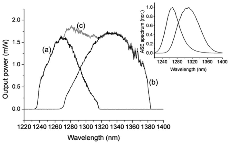
Fig. 3 shows the laser output spectrum measured with an optical spectrum analyzer in peak hold mode. The rotational rate of the polygon scanning mirror was 500 revolutions per second, providing a sweep repetition rate of 20 kHz. At the beginning of a scan period, only the shorter wavelength laser emitted light. As the filter scanned to the center portion of the tuning range, the longer wavelength laser exceeded threshold so that both lasers emitted the same wavelength. After the overlap region of the filter scan, only the longer wavelength laser produced light until the beginning of the subsequent scan. When the polygon mirror was held fixed, the center wavelength of the two lasers matched to within 0.05 nm over the entire wavelength sweep range. The edge-to-edge tuning range of the laser with the shorter center wavelength SOA (Kamelian) was 78 nm (56 nm at 3 dB) from 1238 to 1316 nm; that for the longer wavelength SOA (Philips) was 112 nm (91 nm at 3 dB) from 1271 to 1383 nm. The wavelength sweep of the combined laser output ranged over 145 nm edge-to-edge (132 nm at 3 dB) from 1238 to 1383 nm. The instantaneous linewidth was determined to be 0.26 nm at a tuning repetition rate of 20 kHz by measuring the coherence function of the laser output using a variable-delay Michelson interferometer. The peak and the average power were 1.8 and 1.35 mW, respectively.
Fig. 3.

Integrated spectrum of (a) the laser based on SOA1, (b) the laser based on SOA2, and (c) two synchronized lasers combined. Inset: Normalized ASE spectrum of each SOA.
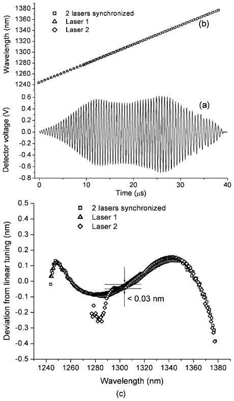
The time-varying laser center wavelength was determined by measuring periods of the interference fringe from a fixed-delay Michelson interferometer during a laser tuning cycle [Fig. 4(a)]. Linear wavelength scanning was obtained over the complete wavelength sweep range of the laser, as shown in Fig. 4(b). Fig. 4(c) depicts the deviation from linear tuning of the two lasers and the combined output. Over the whole wavelength sweep range, the deviation was −0.4 ~ 0.2 nm. The difference in instantaneous laser output wavelengths between the two lasers was less than 0.03 nm, indicating the output spectra of the two lasers were substantially overlapped with each other. However, when the spectra of the two laser outputs are overlapped, significant intensity noise can arise due to a coherent interference between the two. For applications where the coherent noise is problematic, the spectral overlap should be avoided by introducing a wavelength offset between the two outputs greater than individual instantaneous linewidth.
Fig. 4.
(a) Interferogram of the laser measured from a Michelson interferometer with a constant delay. (b) Time-varying laser center wavelength. (c) Laser center wavelength deviation from linear tuning.
The parallel configuration described in Fig. 1(b) was also investigated. Because of the additional cavity loss from the two 50/50 couplers as described earlier, the total wavelength tuning range was only 114 nm (edge-to-edge) which is comparable to that obtained with one SOA (Philips). As mentioned previously, properly designed WDM couplers would enhance the tuning range and reduce the coherent noise of this configuration, but we note that such couplers would be also desirable in the synchronized resonator design in terms of improving the combined output and reducing the coherent noise.
In conclusion, we have demonstrated a wide tuning range high-speed wavelength-swept semiconductor laser. The polygon mirror-based wavelength scanning filter provides linear wavelength tuning over the whole gain bandwidth range of multiple SOAs. With the combination of two semiconductor laser cavities, linear wavelength tuning over 145 nm around 1310 nm was obtained at the tuning repetition rate of 20 kHz.
Acknowledgments
This work was supported in part by a gift from Dr. and Mrs. J. S. Chen to the Optical Diagnostics Program of the Massachusetts General Hospital Wellman Center for Photomedicine.
References
- 1.Wysocki PF, Digonnet MJ, Kim BY. Broad-spectrum, wavelength-swept, erbium-doped fiber laser at 1.55 μm. Opt Lett. 1990;15:879–881. doi: 10.1364/ol.15.000879. [DOI] [PubMed] [Google Scholar]
- 2.Harvey KC, Myatt CJ. External-cavity diode laser using a grazing-incidence diffraction grating. Opt Lett. 1991;16:910–912. doi: 10.1364/ol.16.000910. [DOI] [PubMed] [Google Scholar]
- 3.Yun SH, Boudoux C, Tearney GJ, Bouma BE. High-speed wavelength-swept semiconductor laser with a polygon-scanner-based wavelength filter. Opt Lett. 2003;28:1981–1983. doi: 10.1364/ol.28.001981. [DOI] [PubMed] [Google Scholar]
- 4.Yun SH, Richardson DJ, Culverhouse DO, Kim BY. Wavelength-swept fiber laser with frequency shifted feedback and resonantly swept intracavity acoustooptic tunable filter. IEEE J Sel Topics Quantum Electron. 1997 Aug;3(8):1087–1096. [Google Scholar]
- 5.Eickhoff W, Ulrich R. Optical frequency domain reflectometry in single-mode fiber. Appl Phys Lett. 1981;39:693–695. [Google Scholar]
- 6.Golubovic B, Bouma BE, Tearney GJ, Fujimoto JG. Optical frequency domain reflectometry using rapid wavelength tuning of a Cr4+: forsterite laser. Opt Lett. 1997;22:1704–1706. doi: 10.1364/ol.22.001704. [DOI] [PubMed] [Google Scholar]
- 7.Lexer F, Hitzenberger CK, Fercher AF, Kulhavy M. Wavelength-tuning interferometry of intraocular distance. Appl Opt. 1997;36:6548–6553. doi: 10.1364/ao.36.006548. [DOI] [PubMed] [Google Scholar]
- 8.Chinn SR, Swanson E, Fujimoto JG. Optical coherence tomography using a frequency-tunable optical source. Opt Lett. 1997;22:340–342. doi: 10.1364/ol.22.000340. [DOI] [PubMed] [Google Scholar]
- 9.Yun SH, Boudoux C, Pierce MC, de Boer JF, Tearney GJ, Bouma BE. Extended-cavity semiconductor wavelength-swept laser for biomedical imaging. IEEE Photon Technol Lett. 2004 Jan;16(1):293–295. doi: 10.1109/LPT.2003.820096. [DOI] [PMC free article] [PubMed] [Google Scholar]
- 10.Yun SH, Tearney GJ, de Boer JF, Iftimia N, Bouma BE. High-speed optical frequency-domain imaging. Opt Express. 2003;11:2953–2963. doi: 10.1364/oe.11.002953. [DOI] [PMC free article] [PubMed] [Google Scholar]
- 11.Yun SH, Richardson DJ, Kim BY. Interrogation of fiber grating sensor arrays with a wavelength-swept fiber laser. Opt Lett. 1988;23:843–845. doi: 10.1364/ol.23.000843. [DOI] [PubMed] [Google Scholar]
- 12.Wippich M. Swept-wavelength testing advancements. Lightw Web Exclusive. 2002 Sep 9; [Google Scholar]
- 13.Akiyama T, Ekawa M, Sugawara M, Sudo H, Kawaguchi K, Kuramata A, Ebe H, Morito K, Imai H, Arakawa Y. OFC 2004. Los Angeles, CA: 2004. An ultrawaide-band (120 nm) semiconductor optical amplifier having extremely-high penalty-free output power of 23 dBm realized with quantum-dot active layers. Paper PDP12. [Google Scholar]
- 14.Pudo D, Chen LR, Giannone D, Zhang L, Bennion I. Actively mode-locked tunable dual-wavelength erbium-doped fiber laser. IEEE Photon Technol Lett. 2002 Feb;14(2):143–145. [Google Scholar]
- 15.Chen YF, Lan YP, Wang SC. Efficient high-power diode-end-pumped TEM00 Nd: YVO4 laser with a planar cavity. Opt Lett. 2000;25:1016–1018. doi: 10.1364/ol.25.001016. [DOI] [PubMed] [Google Scholar]
- 16.Schmitt JM, Lee SL, Yung KM. An optical coherence microscope with enhanced resolving power in thick tissue. Opt Commun. 1997;142:203–207. [Google Scholar]
- 17.Tripathi R, Nassif N, Nelson JS, Park BH, de Boer JF. Spectral shaping for nonGaussian source spectra in optical coherence tomography. Opt Lett. 2002;27:406–408. doi: 10.1364/ol.27.000406. [DOI] [PubMed] [Google Scholar]


