Abstract
We describe a strategy to construct three-dimensional (3D) containers with nanoporous walls by the self-assembly of lithographically patterned two-dimensional cruciforms with solder hinges. The first step involves fabricating two-dimensional (2D) cruciforms composed of six unlinked patterns: each pattern has an open window. The second step entails photolithographic patterning of solder hinges that connect the cruciform. The third step involves the deposition of polystyrene particles within the windows and the subsequent electrodeposition of metal in the voids between the polystyrene particles. Following the dissolution of the particles, the cruciforms are released from the substrate and heated above the melting point of the solder causing the cruciforms to spontaneously fold up into 3D cubic containers with nanoporous walls. We believe these 3D containers with nanoporous side walls are promising for molecular separations and cell-based therapies.
Keywords: Self-assembly, photolithography, colloid templating, nanoporous, cell encapsulation
Nanoporous membranes with tunable pore sizes have been fabricated by a variety of methods using inorganic, organic, and composite materials. Most of these membranes are constructed in 2D for applications in sensing and separations. However, as compared to 2D nanoporous membranes, 3D devices with nanoporous side-walls facilitate a higher exposed surface area (enabling greater interaction with the surrounding medium) and can encapsulate cells and other therapeutics for cell-based therapies1–4 and drug delivery.5 Present day, 3D structures with nanoporous walls are based on silicon (Si).1–4 These structures or capsules enclosing specific cells have been utilized to deliver therapeutics for a variety of diseases; however, they tend to be large, i.e., millimeter to centimeter scaled. Additionally, it is still challenging to pattern side-wall nanoporosity in 3D devices in a highly parallel manner while maintaining precise control over pore sizes and anisotropic patterning.
We recently developed a strategy6,7 to construct untethered cubic devices by the self-folding of lithographically patterned 2D cruciforms. The procedure involves the lithographic patterning of planar cruciforms with solder hinges on sacrificial layers deposited above Si wafer substrates. The cruciforms can be released from the surface, and upon heating above the melting point of the solder, they self-assemble into hollow cubic containers due to minimization of surface energy of the molten solder hinges. The containers can subsequently be coated with gold or platinum to render them bio-inert.
Here, we demonstrate that our assembly process enables any micro- or nanoporous membrane that can be patterned in 2D, to be structured and utilized in 3D. Fabricating nanopores on each face of the polyhedra in all three dimensions is critical to allow rapid and efficient biomolecular exchange between encapsulated contents and the external environment. Due to the challenges in patterning nanoscale features with optical lithography (due to diffraction), even in 2D, we have utilized colloidal templating8–18 along with optical lithographic patterning and self-assembly to construct the 3D nanoporous containers. The colloidal patterning enables patterning of nanopores; the optical lithographic patterning defines the 2D cruciform; and the self-assembly converts the porous 2D cruciform into the container.
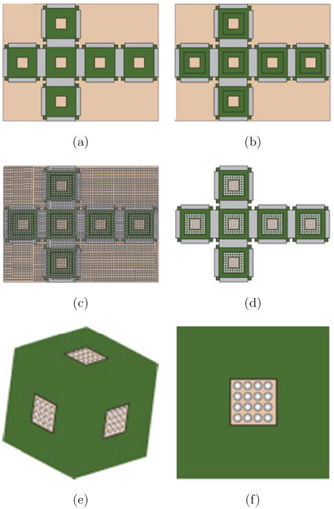
Briefly, as illustrated in Fig. 1, 2D cruciforms (Fig. 1(a)) were first lithographically patterned (in two steps) with square nickel (Ni) faces, 150 μm windows and solder hinges. In order to achieve this patterning, polymethyl methacrylate (PMMA) was spin-coated as a sacrificial layer onto a Si substrate to facilitate the subsequent release of the 2D cruciforms. A metallic chromium/copper (Cr/Cu) seed layer was then evaporated onto the sacrificial layer to create wafer-scale electrical contact for subsequent Ni face and Sn/Pb solder (Techni Solder Matte NF820 60/40) hinge electrodeposition. Then, two steps of lithography were utilized to pattern the 500 μm faces with 150 μm windows and solder hinges. A third-step of lithography was utilized to pattern 300 μm windows on each face (Fig. 1(b)) for particle templating. After colloidal deposition (Fig. 1(c)), Ni was again electrodeposited, filling the resulting voids between the assembled particle multilayers. Then, the photoresist and particles were dissolved using toluene. The 2D cruciform (Fig. 1(d)) was released from the Si wafer by dissolving the seed and sacrificial layers, and self-assembly (Fig. 1(e)) was carried out above the melting point of the solder (m.p. ∼ 183°C) in a high-boiling-point solvent.6
Fig. 1.

Schematic diagram depicting top views of the key steps in the fabrication of nanoporous containers. (a) two steps of lithography were used to define the nickel (Ni) faces (green regions), 150 μm windows, and solder hinges (grey regions). (b) A third-step of photolithography was used to define a larger 300 μm window for colloidal templating. (c) PS paricles were deposited all over the wafer and on the cruciforms. (d) Ni was electrodeposited; the PS particles were dissolved and the cruciform was released from the substrate by etching the seed and sacrificial layers. (e) the 3D container with nanoporous faces was self-assembled by heating above the melting point of the solder hinges. (f) A schematic diagram of a single outer face of the cubic container showing the patterned window and wall porosity (color online).
Fig. 2.

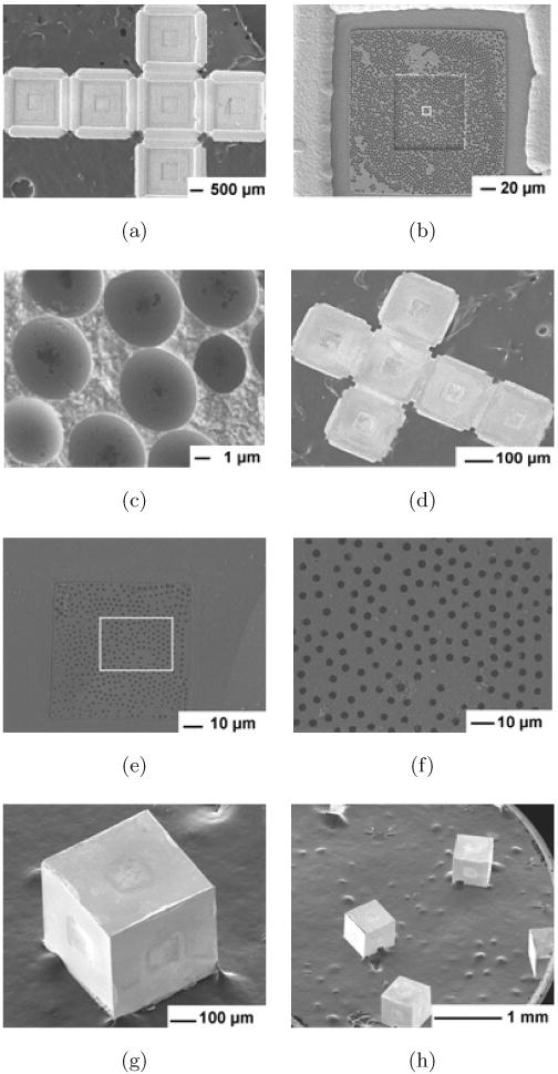
SEM images of microporous containers constructed by templating 6 μm PS particles. SEM image of the top view (which forms the inside of the faces of the container after self-assembly) of (a) the 2D cruciform after Ni electrodeposition and (b) of a single face with (c) zoomed-in detail of the square region marked in (b). SEM image of (d) the bottom side (which forms the outside of the face of the container after self-assembly) of the 2D cruciform after release from the substrate with progressively zoomed-in images of (e) a single face, and (f) the micropores marked in (e). SEM images of (g) a single and (h) many porous containers.
In order to demonstrate the versatility of the process, we fabricated containers with two pore sizes by templating 6 μm and 750 nm PS particles (Polysciences). These particles produced pore sizes of approximately 3 μm and 63 nm, respectively. Templating was achieved as follows: the particles were diluted with deionized water (1:4) and pipetted onto the entire wafer (Fig. 1(c)). The wafer was then placed in a high humidity chamber (for a period of two to four days depending on the particle size) to reduce the evaporation rate of water from the surface of the wafer. This low evaporation rate enabled a homogeneous distribution of PS particles all over the wafer. We then electrodeposited Ni and subsequently dissolved the particles. Electrode-position occurred only on exposed metallic regions within the 300 μm windows that were covered by PS particles. The overall Ni face thickness was approximately 8 and 4.8 μm when 6 μm and 750 nm PS particles were used, respectively.
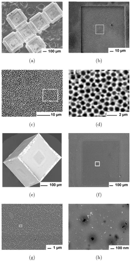
Figures 2(a)–2(c) show scanning electron microscopy (SEM) images of the top view of the 2D cruciform after dissolution of the 6 μm PS particles, seed and sacrificial layers. It is clear from Figs. 2(b)–2(c) that the Ni film with spherical micro-sized cup-shaped regions was selectively electrodeposited around the particles within the patterned window. It should be noted that the pore size on the outer side of the faces of the containers was always much smaller than the pores and spherical regions observed on the inside of the faces. The diameter of the spherical regions (∼ 5 μm) was related to the number of particle layers formed, elecrodepostion time and thickness, and the diameter of particle used (6 μm). Within each large spherical region there was a smaller hole that was the point of contact between particles within the multilayer. This hole represents the pore size formed by the colloidal templating. The average diameter of the pore on the bottom side (which forms the outside of the faces of the container after self-assembly) was 3 μm ± 300 nm. Upon heating, containers with these porous windows were assembled (Fig. 2(g)) in parallel, i.e., containers could be fabricated en masse (Fig. 2(h)). For smaller pore sizes, we templated smaller (750 nm) PS particles (Fig. 3). In this case, the diameter of the spherical regions (Fig. 3(d)) was 657 ± 40 nm, while the diameter of the pores on the outer faces of the container was 63 ± 30 nm (Fig. 3(h)). We estimate that the porosity within the window regions on the outside of the faces of the containers was in the range of 8 to 12% (micropores) when templated with the 6 μm particles and between 0.6 to 5% (nanopores) when templated with 750 nm particles. The overall size of the window can be readily increased or decreased by photolithography, depending on the desired overall porosity. It should also be noted that solder reflow enables the seams to be fused completely, therefore we do not anticipate any leakage or porosity at the seams (joints) of the containers. Nevertheless, additional characterization is needed to confirm this feature. We also note that self-assembled containers with solder joints have good mechanical strength and can be handled (by pipetting) without breakage.
Fig. 3.

SEM images of containers with approximately 63 nm sized pores, constructed by templating 750 nm PS particles. SEM image of (a) the top view (which forms the inside of the faces of the container after self-assembly) of the 2D cruciform after Ni electrodeposition, and (b) of a single face with (c)–(d) progressively zoomed-in detail of the region marked in (b). SEM image of (e) a nanoporous container after assembly and (f)–(h) progressively zoomed-in detail of the outer face of the container.
In summary, we have demonstrated a new strategy to fabricate containers with micro- and nanoscale wall porosity. The process is cost-effective and enables containers to be fabricated in a parallel wafer-scale manner. The pore size formed depends on the particle size used for templating, and can be controlled. Previously, we have shown that containers can be experimentally fabricated with sizes ranging from 15 μm to 2 mm and theoretically down to the nanoscale.6 Thus, it should now be possible to construct nanoporous containers over a large range of volumes for a variety of encapsulants. Another attractive feature of this process is that it is possible to construct containers with anisotropic porosity. Containers constructed with these materials have also passed standard toxicity tests and in vivo implantation.19 Hence, we envision the use of these containers as cell encapsulants in cell therapy and three-dimensional nanoporous membranes for biomolecular separations. As with other nanoporous membranes, biofouling remains a challenge, but can be reduced by coating the pores with anti-fouling molecular coatings.20 Finally, in this report, we have demonstrated the use of only one strategy (i.e., particle templating) to pattern the 2D membrane; however, the self-assembly concept allows any patterned 2D membrane (such as those patterned by anodization) to be structured and utilized in 3D.
Acknowledgments
This material is based upon work supported by the National Institutes of Health under Grant Number 1R21EB007487-01A1. Any opinions, findings, and conclusions or recommendations expressed in this material are those of the authors and do not necessarily reflect the views of the funding agency.
References
- 1.Adiga S, Curtiss L, Elam J, Pellin M, Shih CC, Shih CM, Lin S, Su Y, Gittard S, Zhang J, Narayan R. JOM. 2008;60:26. [Google Scholar]
- 2.Desai T, Hansford D, Kulinsky L, Nashat A, Rasi G, Tu J, Wang Y, Zhang M, Ferrari M. Biomed Microdev. 1999;2:11. [Google Scholar]
- 3.Heo K, Yoon J, Jin K, Jin S, Ree M. IEE Proc Nanobiotechnol. 2006;153:121. doi: 10.1049/ip-nbt:20050020. [DOI] [PubMed] [Google Scholar]
- 4.Rosenbloom A, Sipe D, Shishkin Y, Ke Y, Devaty R, Choyke W. Biomed Microdev. 2004;6:261. doi: 10.1023/B:BMMD.0000048558.91401.1d. [DOI] [PubMed] [Google Scholar]
- 5.LaVan DA, McGuire T, Langer R. Nat Biotechnol. 2003;21:1184. doi: 10.1038/nbt876. [DOI] [PubMed] [Google Scholar]
- 6.Leong T, Lester P, Koh T, Call E, Gracias DH. Langmuir. 2007;23:8747. doi: 10.1021/la700913m. [DOI] [PubMed] [Google Scholar]
- 7.Leong T, Gu Z, Koh T, Gracias DH. JACS. 2006;128:11337. doi: 10.1021/ja063100z. [DOI] [PubMed] [Google Scholar]
- 8.Imahof A, Pine DJ. Nature. 1997;389:948. [Google Scholar]
- 9.Takahara YK, Ikeda S, Tachi K, Sakata T, Hasegawa T, Mori H, Matsumura M, Ohtami B. Chem Commun. 2005:4205. doi: 10.1039/b507123b. [DOI] [PubMed] [Google Scholar]
- 10.Bartlett PN, Birkin PR, Ghanem MA. Chem Commun. 2000:1671. [Google Scholar]
- 11.Jiang P, Bertone JF, Colvin VL. Science. 2001;291:453. doi: 10.1126/science.291.5503.453. [DOI] [PubMed] [Google Scholar]
- 12.Velev OD, Lenhoff AM, Kaler EW. Science. 2000;287:2240. doi: 10.1126/science.287.5461.2240. [DOI] [PubMed] [Google Scholar]
- 13.Iskandar F, Iwaki T, Toda T, Okuyama K. Nano Lett. 2005;5:1525. doi: 10.1021/nl050863w. [DOI] [PubMed] [Google Scholar]
- 14.Lou Q, Liu Z, Li L, Xie S, Kong J, Zhao D. Adv Mater. 2001;13:286. [Google Scholar]
- 15.Chai GS, Shin IS, Yu J. Adv Mater. 2004;16:2057. [Google Scholar]
- 16.Gates B, Yin Y, Xia Y. Chem Mater. 1999;11:2827. [Google Scholar]
- 17.Eagleton TS, Searson PC. Chem Mater. 2004;16:5027. [Google Scholar]
- 18.Yi G, Moon JH, Yang SM. Chem Mater. 2001;13:2613. [Google Scholar]
- 19.Randall CL, Leong TG, Bassik N, Gracias DH. Adv Drug Delivery Rev. 2007;59:1547. doi: 10.1016/j.addr.2007.08.024. [DOI] [PubMed] [Google Scholar]
- 20.Dai ZW, Wan LS, Xu ZK. J Membr Sci. 2008;325:479. [Google Scholar]


