Abstract
Beating heart intracardiac procedures promise significant benefits for patients, however, the fast motion of the heart poses serious challenges to surgeons. We present a new 3D ultrasound-guided motion (3DUS) compensation system that synchronizes instrument motion with the heart. The system utilizes the fact that the motion of some intracardiac structures, including the mitral valve annulus, is largely constrained to translation along one axis. This allows the development of a real-time 3DUS tissue tracker which we integrate with a 1 degree-of-freedom actuated surgical instrument, real-time 3DUS instrument tracker, and predictive filter to devise a system with synchronization accuracy of 1.8 mm RMSE. User studies involving the deployment of surgical anchors in a simulated mitral annuloplasty procedure demonstrate that the system increases success rates by over 100%. Furthermore, it enables more careful anchor deployment by reducing forces to the tissue by 50% while allowing instruments to remain in contact with the tissue for longer periods.
1 Introduction
Beating heart intracardiac repairs are now feasible with the use of real-time 3D ultrasound (3DUS) guidance [1]. These procedures avoid the need for cardiopulmonary bypass, which has a number of adverse effects including increased stroke risk and cognitive impairment [2]. Operating on the beating heart has the added advantage of allowing the surgeon to evaluate the status of the repair while the heart continues to function. Although beating heart procedures have many clear benefits, heart motion can make the safe manipulation of its tissues extremely challenging. This is particularly the case for the mitral valve, which is comprised of fast-moving and delicate tissues.
A promising solution to these problems is to employ a robotic motion compensation system to synchronize instrument motion with the heart. This approach has been studied extensively for coronary artery bypass graft procedures using multiple degree-of-freedom (DOF) robots and exploiting near periodicity in heart motion to synchronize with the external surface of the heart [3][4]. Operating on the mitral valve, though, provides additional challenges from working inside the heart. First, the restricted confines make using a multi-DOF robot difficult. Second, 3DUS must be used for guidance because it is currently the only real-time volumetric imaging technique that can image tissue through blood. Its use introduces time delays [5] and can make tracking of the tissue target difficult due to poor shape definition [1].
In this work, we present a 3DUS-guided motion compensation system that overcomes these challenges to beating heart intracardiac procedures. The design of the system is guided by the clinical observation that the rapid motion of the annulus is dominated by translation along a single axis between the left atrium and left ventricle [6]. This allows the use of a simplified 1 DOF motion compensation system that can be used for surgical procedures like the anchor driving found in mitral annuloplasty. In the following we describe this system and its components, then validate its performance in a user study.
2 Motion Compensation System
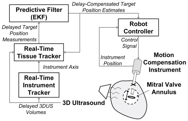
In previous work we developed a real-time 3DUS instrument tracker [5], motion compensation instrument [6], and quasiperiodic predictive filter [7] for beating heart intracardiac surgery. Here we develop a real-time 3DUS tissue tracking technique and integrate these technologies into a system for 3DUS-guided motion compensation (Fig. 1). The resulting system enables beating heart procedures on intracardiac structures that undergo rapid translational motions primarily along one axis, like the mitral valve annulus [6]. The system comprises an actuated 1 DOF instrument commanded by a predictive filter that is in turn fed time-delayed, noisy measurements from a real-time 3DUS tissue segmentation algorithm. The filter used to command the actuator, an extended Kalman filter (EKF), accurately estimates and predicts the annulus trajectory by exploiting quasiperioidicity in its motion. In addition to being used to feed-forward the trajectory of the cardiac target to the instrument controller for motion synchronization, it is fed back to the tissue tracker to assist in detecting the target.
Fig. 1.
Motion compensation system.
2.1 Motion Compensation Instrument
The motion compensation instrument (MCI) is a handheld anchor deployment device that actively cancels the dominant 1D motion component of the mitral valve annulus (Fig. 2A). It incorporates a voice coil linear motor (NCC10-15-023-1X, H2W Technologies, Valencia, CA, USA) for actuation of the anchor deployment stage up to speeds and accelerations of 1490 mm/s and 103000 mm/s2. The instrument is controlled with a slightly underdamped response by a 1 kHz PID servo loop and has a −3 dB point of 35.0 Hz (−40 dB/dec roll off rate). The resulting instrument is capable of following the fast motion of the mitral annulus with an effective delay of 10 ms, as depicted in Fig. 2B. A detailed description of the MCI design is given in [6].
Fig. 2.
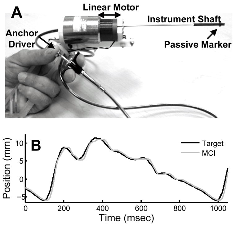
(A) MCI hardware prototype. (B) MCI tracking recorded mitral valve annulus motion.
2.2 Quasiperiodic Predictive Filter: Extended Kalman Filter
The intrinsic time delays in 3DUS make direct visual servoing of the MCI potentially dangerous. We estimate delays of ≈70 ms in the acquisition, transmission, and computation times associated with 3DUS [5] - sufficient time for the mitral valve annulus to traverse the majority of its path at end systole [6]. Left uncompensated, these delays would lead to collisions between the instrument and annulus that would result in tissue damage. To avoid this outcome, we exploit the near periodicity of the mitral valve trajectory to predict its path and hence compensate for time delay.
Prior research in motion compensated coronary artery bypass graft has investigated prediction using an adaptive filter bank [4], an estimator based on Takens theorem [8], and a vector autoregressive least squares estimator [9]. In this work, we employ an extended Kalman filter (EKF) with an explicity quasiperiodic model, which is effective for 3DUS-guided mitral valve motion compensation [7]. To model quasiperiodic heart motion, we consider the following m-order time-varying Fourier series with an offset
| (1) |
where y(t) is the target position in ultrasound coordinates, c(t) is the offset, ri(t) are the harmonic amplitudes, and , with heart rate ω(t) and harmonic phases φi(t). This parameterization was introduced in [10] and shown to be a robust model for mitral annulus tracking with m = 8 harmonics [7].
Defining the state vector x(t) ≜ [c(t),ri(t),ω(t),θi(t)]T, i ∈ (1, …, m) and assuming that c(t), ri(t), ω(t), and φi(t) evolve through a random walk, the state space model for this system is
where h(x(t)) ≜ y(t) from (1),
is zero mean Gaussian noise, and μ(t) ~  (0, Q) is the random step of the states assumed to be drawn from a zero mean multivariate normal distribution with covariance matrix Q.
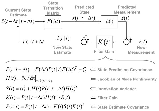
Prediction with this model requires estimation of x(t); a nonlinear estimation problem owing to the measurement function, h(x(t)). We employ the EKF, a nonlinear filtering method that approximates the Kalman filter through linearization about the state estimate x̂(t − Δt|t − Δt). The EKF is computed in real-time using the recursion given in Fig. 3. Details may be found in [7].
Fig. 3.
Extended Kalman filter recursion.
2.3 Real-Time Tissue Tracking
Automatic, real-time segmentation of a tissue target in 3DUS is challenging due to poor shape definition and the number of computations required to process volumes at 28 Hz (the 3DUS sampling rate). In this work we achieve real-time tissue tracking in 3DUS by making use of the instrument to designate a tissue target in the 3DUS volumes, essentially by pointing at it. Tracking is then reduced to detecting the tissue that is along the instrument axis.
This approach first requires locating the instrument in 3DUS. We accomplish this with a GPU-based Radon transform algorithm that finds the instrument axis in real-time 3DUS [5]. When the instrument is stationary and not in contact with the tissue, both are readily detected by peaks in an intensity-based objective function that is calculated on a 2D image slice through the instrument shaft. An example of this is shown in Figs. 4A and C, where a priori knowledge of the 3DUS probe placement relative to the instrument allows the identification of the left-most peak in the objective as the passive marker on the instrument. The peak immediately following it to the right is the tissue target.
Fig. 4.
Example ultrasound slices along instrument shaft when instrument is not in contact with target (A) and when it is in contact with target (B). The corresponding intensity-based objective functions are shown in (C) and (D), with the EKF-predicted target location shown in (D). The x axis is parallel to instrument axis (white dash).
Complications in the segmentation of the passive marker can arise when the instrument moves to compensate target motion or comes into contact with the target. Specularities on the shaft can be confused with the passive marker and it can be difficult to distinguish the instrument tip when it may in fact be embedded in the tissue (Figs. 4B and D). These challenges are overcome by using the EKF to predict the location of the target in the current frame, in an analogous manner to gating in radar target tracking. The peak in the objective that is nearest to the predicted location is taken as the target peak, thereby obviating the need to further segment the instrument marker.
3 Performance in a Surgical Task
The accuracy and benefits of the proposed motion compensation system were assessed through a study of user performance in an in vitro beating heart surgical task. Ten subjects (seven male, three female, ages 20–34) were instructed to use the MCI to drive surgical anchors (similar to staples, deployed from the tip of the instrument shaft) into a tissue phantom that simulated the motion of the mitral valve annulus in a water tank. The MCI either provided motion compensation through the system described in the preceding section or the MCI was set to act as a solid, noncompensating instrument.
3.1 Experimental Setup
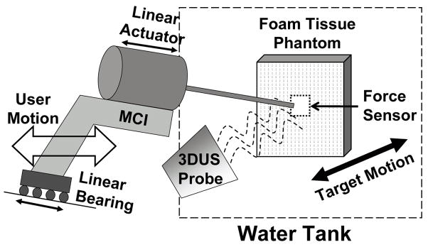
The user trials were conducted in conditions that mimic those expected in a beating heart mitral valve annuloplasty procedure. Fig. 5 depicts the setup. Valve motion was simulated by a cam follower mechanism that replicates the dominant 1D motion component of the human mitral valve (Fig. 2B), as determined in [6]. A tissue phantom of 2 cm thick polyethylene foam was affixed to a load cell (Kistler, Spartanburg, SC, USA) that measured the forces applied by the MCI during the task, then mounted to the cam and positioned in a water tank. The cam simulated a heart beat of 60 beats per minute. The MCI was aligned at roughly 15 deg to the motion axis of the target and contrained to move in 1 DOF by a linear bearing guide rail. Subjects viewed the task through the monitor of the 3DUS machine (SONOS 7500, Philips Medical, Andover, MA, USA), which was set up to image the target and instrument simultaneously. A potentiometer measured target position for off-line assessment of system accuracy.
Fig. 5.
Experimental setup for user trials
The motion compensation system used a dual CPU AMD Opteron 285 2.6 GHz PC with 4 GB of RAM to process the ultrasound data, control the MCI, and record the force readings from the load cell. The 3DUS machine streamed volumes to the PC over a 1 Gb LAN using TCP/IP. A program written in C++ retrieved the ultrasound volumes and loaded them onto a GPU (7800GT, nVidia Corp, Santa Clara, CA) for real-time instrument axis detection. Subsequent tissue tracking, predictive filtering, and control algorithms were implemented in C++ on the CPU.
3.2 Testing Protocol
The subjects were instructed to deploy anchors into the moving tissue phantom with the MCI in a series of trials. They were informed that the dual criteria for a successful trial were that the anchor be securely deployed in the target and that the forces applied to the target by the MCI during the task not exceed 15 N (the puncture force as determined in pilot studies on excised porcine mitral valve annulus). The subjects were taught to use the MCI’s anchor driver mechanism and trained to recognize the “feeling” of forces up to 15 N when pushing the MCI into a stationary target. When the subjects became confident in their sense of the forces applied, they were given six practice anchoring trials with the moving target: three with motion compensation and three with a solid instrument. After training, the subjects proceeded to perform the task in ten trials (five with motion compensation and five with a solid instrument) in randomized order. The outcome of each stapling attempt and the amount of force applied was shared with the subject directly after each trial.
3.3 Results
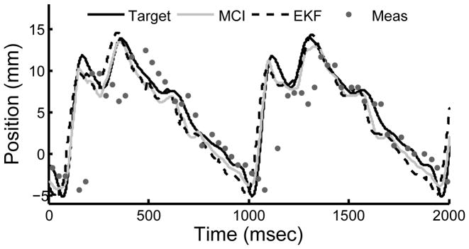
The motion compensation system provided instrument synchronization to the target with 1.8 mm RMS error. A representative example from a user trial is shown in Fig. 6. Position measurements from the tissue tracker had RMS errors of 2.5 mm and were delayed by 68 ms. Both error and time delay were mitigated by the EKF, which had RMS prediction errors of 1.7 mm.
Fig. 6.
Example of MCI tracking the mitral annulus target. Measurements from the tissue tracker and EKF predictions are shown.
Motion compensated anchor driving provided a mean failure rate that was roughly 60% less than that observed for a solid instrument (Fig. 7A). A statistically significant difference between the means (26.0±7.3% for motion compensation and 68.0±5.3% for a solid instrument, mean ± standard error) was apparent using a two-sided t-test (p = 0.0002). It should be noted that a subset of four subjects obtained 0% failure rates with motion compensation and 70.0 ± 12.9% without. The three engineers participating in the study belonged to this subset.
Fig. 7.
Mean failure rates (A) and mean continuous contact time (B) with motion compensation and with a solid instrument. Error bars indicate standard error.
Motion compensation also enabled the subjects to place the instrument in continuous contact with the target for nearly three times longer than with a solid instrument (Fig. 7B). On average, subjects kept constant contact on the target for 7.7 ± 0.6 sec with motion compensation and 2.6 ± 0.2 sec without. This difference between the means is statistically significant (p < 0.0001). The range of continuous contact times observed over all motion compensation trials was 2.0 – 17.5 sec while the range for the solid instrument was 0.7 – 7.9 sec.
The forces applied to the target were reduced for trials using motion compensation. Fig. 8 shows a histogram of force samples for all trials for the motion compensated and solid instrument cases. The 95th percentile of forces for the solid instrument (10.2 N) is nearly twice that seen for motion compensation (5.8 N).
Fig. 8.
Histogram of applied forces over all user trials. 95th percentiles are shown.
4 Discussion and Conclusions
These results demonstrate that the 3D ultrasound-guided motion compensation system described here provides substantial performance gains for surgical tasks on beating mitral valve targets. By exploiting the predominantly 1 DOF motion of the mitral valve, we were able to develop novel solutions to actuating an instrument within the confines of the heart and tracking tissue targets in real-time 3D ultrasound. A quasiperiodic predictive filter enabled compensation for the time delays in the system so that the instrument could be actuated to track fast-moving tissue without lag, as evidenced in our in vitro experiments.
To the knowledge of the authors, this is the first demonstration of a fully integrated surgical motion compensation system based on real-time volumetric image data that can interact with the beating heart. Using the system, subjects achieved success rates for a surgical anchor deployment task that were more than double those achieved with a non-compensated instrument. Furthermore, the system permitted more careful placement of the anchors by reducing the forces applied and prolonging the amount of continuous contact between the instrument and the target.
While motion compensated anchor driving had relatively low failure rates in our study, we anticipate that it can be driven to nearly zero with additional user training and a small modification to the instrument. The flawless performance of users with technology experience (e.g., engineers) suggests that the other users could benefit from more practice. Indeed, several users were confused by ultrasound visualization and impaired by the inertial forces resulting from the actuator’s moving mass, which could be difficult to distinguish from contact forces. This led to cases where the user would not push the instrument firmly into contact with the target. Modification of the instrument to include a counterbalancing mass will mitigate the loss in haptic feedback due to inertial effects. Further research is underway to evaluate the efficacy and usability of this motion compensating system in in vivo beating heart mitral annulus repair.
Acknowledgments
This work is supported by the US National Institutes of Health under grant NIH R01 HL073647-01.
References
- 1.Cannon J, et al. Real-time three-dimensional ultrasound for guiding surgical tasks. Computer Aided Surgery. 2003;8(2):82–90. doi: 10.3109/10929080309146042. [DOI] [PubMed] [Google Scholar]
- 2.Murkin J, et al. Beating heart surgery: why expect less central nervous system morbidity? Annals of Thoracic Surgery. 1999;68:1498–1501. doi: 10.1016/s0003-4975(99)00953-4. [DOI] [PubMed] [Google Scholar]
- 3.Nakamura Y, Kishi K, Kawakami H. Heartbeat synchronization for robotic cardiac surgery. Proc. ICRA; Seoul Korea. May 2001; pp. 2014–2019. [Google Scholar]
- 4.Ginhoux R, et al. Active filtering of physiological motion in robotized surgery using predictive control. IEEE Transactions on Robotics. 2006;21(1):67–79. [Google Scholar]
- 5.Novotny P, et al. GPU based real-time instrument tracking with three-dimensional ultrasound. Medical Image Analysis. 2007;11:458–464. doi: 10.1016/j.media.2007.06.009. [DOI] [PMC free article] [PubMed] [Google Scholar]
- 6.Kettler D, et al. An active motion compensation instrument for beating heart mitral valve surgery. Proc. IEEE IROS; San Diego USA. Oct 2007. [Google Scholar]
- 7.Yuen S, Novotny P, Howe R. Quasiperiodic predictive filtering for robot-assisted beating heart surgery. Proc. IEEE ICRA; Pasadena USA. May 2008. [Google Scholar]
- 8.Ortmaier T, et al. Motion estimation in beating heart surgery. IEEE Transactions on Biomedical Engineering. 2005 Oct;52(10):1729–1740. doi: 10.1109/TBME.2005.855716. [DOI] [PubMed] [Google Scholar]
- 9.Franke T, Bebek O, Cavusoglu C. Improved prediction of heart motion using an adaptive filter for robot assisted beating heart surgery. Proc. IEEE IROS; San Diego USA. Oct–Nov 2007; pp. 509–515. [Google Scholar]
- 10.Parker P, Anderson B. Frequency tracking of nonsinusoidal periodic signals in noise. Signal Processing. 1990;20:127–152. [Google Scholar]


