Abstract
Motivated by a developmental gas embolotherapy technique for selective occlusion of blood flow to tumors, we examined the transport of a pressure-driven semi-infinite bubble through a liquid-filled bifurcating channel. Homogeneity of bubble splitting as the bubble passes through a vessel bifurcation affects the degree to which the vascular network near the tumor can be uniformly occluded. The homogeneity of bubble splitting was found to increase with bubble driving pressure and to decrease with increased bifurcation angle. Viscous losses at the bifurcation were observed to affect the bubble speed significantly. The potential for oscillating bubble interfaces to induce flow recirculation and impart high stresses on the vessel endothelium was also observed.
INTRODUCTION
This work is primarily motivated by a novel concept of gas embolotherapy to treat tumors.1, 2, 3, 4, 5, 6, 7, 8, 9, 10, 11, 12 In this potential treatment modality, transvascular perfluorocarbon (PFC) droplets (6 μm in diameter) are selectively vaporized using high intensity ultrasound [acoustic droplet vaporization (ADV)] at a desired location near or in the tumor microcirculation to form substantially larger gas bubbles (∼150 times volume expansion) which then occlude blood flow and induce tumor infarction. ADV in small vessels has the potential to induce a range of bioeffects, but vaporizing droplets too far from the tumor may lead to undesired collateral infarction of healthy tissue. Consequently, understanding the transport of bubbles, which are long compared to microvessel diameters, is essential to designing treatment strategies. We anticipate that the following sequence of events occurs after ADV in order for a bubble to occlude blood flow. (a) The bubble, which initially does not contact the vessel wall, is transported along by the blood flow. These bubbles are typically long compared to the vessel diameter (2–10 times the vessel diameter), especially near their ultimate lodging location. (b) After traveling through constrictions, bifurcations, or due to other mechanisms such as gravity or chemical effects, the bubble comes close enough to the vessel wall that it may contact the endothelium and form a contact line which is dominated by surface tension forces. In this step, the bubble may continue to slide along the vessel wall or may become immobilized immediately. (c) The bubble becomes immobilized or lodged when the driving pressure cannot overcome the surface tension resisting the motion of the bubble.
The homogeneity of bubble delivery is expected to determine the uniformity of tumor infarction. Previous studies have used bench top experiments to investigate the splitting and lodging behavior of bubbles as they travel through bifurcations at arterial, arteriolar, and capillary levels.3, 4, 5 Theoretical quasisteady models were presented to explain bubble splitting and lodging,3, 4 but these models do not provide information regarding the stress and velocity fields as the bubbles travel through bifurcations. In previous work, we examined the dynamics of rapidly expanding bubbles during ADV and the associated flow field and wall stresses, in rigid and flexible tubes, using a cut-cell finite-volume method.11, 12 In other work, we studied sticking and sliding of a small (compared to vessel diameter) bubble along a microvessel wall using the boundary element method (BEM).6, 13, 14
Previous experiments have shown that a bubble can either travel through a bifurcation without contacting the wall or move in a “stick and slip” or continuous motion while contacting the wall.3 In our microchannel experiments we observed that bubbles usually contacted the wall, especially at low pressures, and we investigated a hysteresis region in which the bubble did not split evenly even with no effect of gravity.4 We concluded that at low pressures or low bubble speeds the film thickness disappears and the bubble can contact the wall. Previous studies have demonstrated that a film develops between the bubble and the channel wall, but this film decreases in thickness as the bubble speed or capillary number decreases.15, 16, 17
Transport of microbubbles is also relevant to air embolism18, 19, 20, 21 where bubble entrapment is undesirable. Advancements in microfluidic devices necessitate an improved understanding of the dynamics of bubbles traveling through bifurcations since bifurcations are used in microchannel mixing devices where bubble entrapment becomes an important issue. Recently bubbles in nano- and microfluidic circuits have attracted interest for a variety of applications,22 including removal of bubbles from channels,23 inducing and controlling flow,24, 25, 26, 27 and in facilitating femtosecond laser nanomachining.28 Previous fundamental fluid mechanics studies have considered the time-dependent movement of a semi-infinite bubble in a channel with film thickness29 and the steady movement of a semi-infinite bubble contacting the channel walls.30 Others have investigated the transport of small droplets through bifurcations.31 However, the literature contains very little work on long bubbles moving through bifurcations.
Consequently, this study considered the transport of a pressure-driven semi-infinite bubble which contacts the parent channel walls of a bifurcation as an initial model of long microbubble transport through microvessel bifurcations. We use the BEM to model a wall-contacting bubble traveling through a bifurcation in a two-dimensional channel. This simplified model will provide information about stresses and velocities as the bubbles slide along the vessel wall. Using the BEM will allow us to study a contacting bubble with faster computing times and a precise location and shape of the bubble interface, which is important in calculation of pressures, stresses, and velocities in two phase flows. Even though this model does not consider a finite bubble and three-dimensional effects, which may be important, it provides valuable information about the stresses and velocities near the contact line and allows us to compare computational work to previous experimental and theoretical models. Our aim is to better understand the bubble splitting behavior, the corresponding velocity and pressure fields in the liquid surrounding the bubble, and the shear stress along the wall.
MODEL
Governing equations
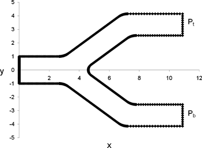
The model presented here considers the time-dependent motion of a semi-infinite bubble through a geometrically symmetric two-dimensional bifurcating channel (Fig. 1). The liquid surrounding the bubble is incompressible and Newtonian. Since the Reynolds numbers in the microcirculation are low (Re⪡1), Stokes flow is considered. The governing equations are the continuity and Stokes equations. The dimensionless forms are
| (1) |
| (2) |
where and p are the velocity and pressure, respectively. Nondimensionalization has been performed using L*=half width of the parent channel as the characteristic length scale (Fig. 1), U*=γ*∕μ* as the velocity scale (a common choice for interfacial flows, where γ* is the surface tension and μ* is the dynamic viscosity), and P*=γ*∕L* as the pressure scale. Bo=rga2∕σ is the Bond number, where g is the acceleration due to gravity, and is the unit vector in the direction of gravity. Time t is nondimensionalized by L*∕U*.
Figure 1.
Channel geometry and example of a boundary mesh. The bubble enters the bifurcation through the parent channel on the left and moves to the right. Pbub is the driving pressure of the bubble, Pb and Pt are the pressure at the bottom and top outlets, respectively.
Initial and boundary conditions
The bubble interface is initially at the parent tube entrance (Fig. 1). The bubble contacts the channel walls and is driven by a constant dimensionless bubble pressure Pbub. The top and bottom daughter channels have dimensionless outlet pressures of Pt and Pb, respectively, which may have different values.
The velocity of the two moving contact lines is computed using Tanner’s law32, 33 as follows:
| (3) |
where θD is the dynamic contact angle (varies with time) between the bubble surface and channel wall at the contact line, while θS is the static contact angle (an “equilibrium” value corresponding to a stationary bubble). Note that with our choice of velocity scale the relative magnitudes of viscous and surface tension forces express themselves as a “contact line capillary number” in the dimensionless contact line velocity ucl. It was observed that choosing θS very close or the same as the dimensionless pressure ensures that the contact line moves with the bubble meniscus. This guideline was followed in all our simulations since this closely represents our experimental observations. As we move away from the contact lines, the velocity on the channel walls linearly decreases to zero over a “slip length” l, i.e., the no-slip boundary condition, to avoid singularities at the contact lines. The slip velocity within the slip length32 is
| (4) |
where x is defined as the distance along the solid boundary from the contact line. Thus, the contact line moves at speed ucl and no-slip applies at the wall at distances greater than the slip length away from the contact line. The stress boundary condition at the bubble interface is given by
| (5) |
where is the nondimensional modified stresses exerted by the two fluids, κ is the curvature of the interface, and is the normal vector pointing into the liquid.
Once the flow field is determined with these boundary conditions, the following kinematic boundary condition is used to advance the interface shape in time:
| (6) |
The kinematic boundary condition implies that at any given point, the interface moves normal to itself with the local normal fluid velocity. Once the interface is advanced in time, we solve for the flow field for the new bubble shape with the same boundary conditions, and the algorithm is repeated to step the interface in time.
Numerical method
The solution of linear, elliptic, homogeneous, partial differential equations may be represented by boundary integrals involving the unknown function and its derivatives. For two-dimensional Stokes flow,
| (7) |
where C is the selected flow boundary, is the modified stress, is the modified stress tensor, is the normal pointing into the domain, and ckj is the tensor due to stress jump at the boundaries (δkj∕2 for smooth boundaries). Gij and Tijk are the two-dimensional Stokeslet and the associated stress field, respectively, defined as
| (8) |
| (9) |
This formulation allows us to use the BEM.34, 35, 36 We use quadratic elements to compute the integrals in Eq. 7. A ten-point regular Gaussian quadrature is used if x0 does not lie on the element. If x0 does lie on the element being evaluated, we use a ten-point logarithmic quadrature to evaluate the portions of the integral that involve the logarithmic singularity. This results in a matrix equation, which we solve for the unknown stress or velocity components at each node by Gauss elimination with partial pivoting. By using Tanner’s law, described in Sec. 2B, we avoid stress singularities at the contact line. An example of schematic of the discretized boundary is shown in Fig. 1.
The curvature of the bubble interface κ was computed using cubic splines. Equation 6 was used to step the bubble interface node points in time using either a forward Euler or Adams–Bashforth scheme. Once all components of stress and velocity are determined on the boundary at a particular time step, velocity and stress at any interior point can be determined using the version of Eq. 7 for x0 not on the boundary in which ckj corresponds to the identity matrix. At select time steps, the velocity and pressure fields in the liquid were computed by meshing the interior domain using a constrained Delaunay mesh generator.37
RESULTS AND DISCUSSION
Computational parameters and numerical considerations
Simulations were conducted using our in house BEM code for a range of physiologically relevant dimensionless parameter values for arterioles and capillaries. Based on the surface tension of a PFC or air bubble with the surrounding blood, the dimensionless driving pressures in arterioles and capillaries can range from 7 to 1 depending on the vessel size, which ranges from 5 to 50 μm in diameter. In the model presented here, the driving pressure is equal to the pressure inside the bubble because we model a semi-infinite bubble. This driving pressure will be equivalent to the difference in pressure between the rear and front meniscus, which will be the pressure difference driving the bubble through a vessel or a bifurcating vessel, and the pressure difference in the bubble interface will determine the meniscus shape. The values for the parameters used were the same from previous work.3 Bubble and daughter channel outlet pressures were varied, along with the bifurcation angle (angle between the daughter channels) and contact line parameters, to investigate the interface evolution, bubble splitting behavior, and velocity and pressure fields in the surrounding fluid. The bifurcation angles were selected to approximate the typical range of physiological values, 78°–110°. These were the same angles considered in our experimental work.3, 4 Since this study mainly focused on situations where the bubble is close to lodging and Bo is small (10−4–10−6) in arterioles and capillaries, gravity effect was not considered. It is possible to keep Bo if gravitational effects are important as it may be in some regions of the vasculature. Asymmetry was introduced by varying the daughter tube outlet pressures.
The convergence of the code was investigated by varying the number of boundary nodes and time step size (Δt) to achieve graphical convergence of the bubble interface shape following splitting and to maintain stress and velocity tolerances in the range from 10−10 to 10−12. The final geometry had a total of 700 nodes of which 120 were used along the bubble interface. The straight regions of the channel wall had less densely spaced nodes compared to the curved regions. A heavy concentration of nodes was needed in regions where the daughter tubes start and in the carina of the bifurcation. For calculations in the domain interior, different resolutions were used depending on the shape of the bubble at a specific time step. Some cases required more nodes in front of the bubble because of the presence of recirculation regions. The mesh ranged from 8000 to 19 000 nodes. We could use this high a density of interior nodes as the flow-field computation was relatively fast for a specific time step (<5 min). Calculating the bubble evolution and flow field took approximately 24–36 h on one processor of a multiprocessor Sun Fire V880 equipped with 8 Gbytes of random access memory (Sun Microsystems, Santa Clara, CA), and depended on driving pressure Δt and bifurcation geometry.
Splitting behavior
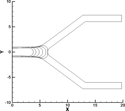
This section focuses on the splitting behavior of bubbles as they traverse through the bifurcation. The first computational model developed considered a bubble that did not contact the walls. Figure 2 shows a model that begins with a thin film between the bubble and the parent tube walls. However, as the bubble begins to split, it is observed that the film thickness between the bubble and the channel wall decreases significantly on the sides of the bifurcation as well as near the carina. A series of simulations were performed with different driving pressures and mesh densities to eliminate the possibility of numerical error. All the solutions seem to suggest that the bubble actually contacts the wall either before it begins to split in the bifurcation or after the splitting starts in the daughter channels. This was later corroborated with microchannel experiments.4 Accordingly, we changed the model and started our simulations with the bubble contacting the parent tube walls, thus forming a three phase contact line that can slide along the channel wall. One possible mechanism of bubble lodging is the surface tension forces at the contact lines being large enough to counteract the pressure difference driving the bubble motion. In the present BEM model we focus on the splitting behavior of bubbles contacting the wall and the velocities and stresses close to the three phase contact line.
Figure 2.
Bubble evolution for the original BEM model of a bubble with a film thickness between. The parameters for this case are Pbub=2, Bo=0, and Pt =Pb=0. The bubble evolution shows that the bubble gets very close to the channel walls on the sides as it begins to split and at the carina of the bifurcation.
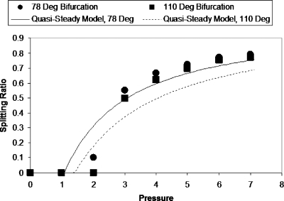
Asymmetry is created by specifying different pressures at the daughter tube outlets. This is similar to the physiological behavior at the arteriolar and capillary levels, where Bo is very small and changes in daughter branch pressures dominate the bubble dynamics at vascular bifurcations. Figure 3 shows the splitting ratio for two geometrically different bifurcations (bifurcation angles of 78° and 110°) with Pt=1 and Pb=0 over a range of driving bubble pressures. The splitting ratio is defined as the ratio of the bubble length in lower daughter channel to the bubble length in upper daughter channel, where the bubble lengths are measured along the centerlines of the daughter channels. Since this model considers a semi-infinite bubble we measure the bubble lengths once any one of them reaches the straight section of the daughter channel. The results show that as the driving bubble pressure increases the splitting ratio increases. We observe that there is a critical pressure at which the bubble does not split and the entire bubble enters the channel with less pressure. This is similar to the effect of capillary number on bubble splitting observed in previously published bench top experiments in which a critical capillary number below which splitting does not occur was identified.3 Splitting ratios predicted by our previous quasisteady one-dimensional model,3 modified to reflect this flow scenario, are plotted for the two bifurcation angles for comparison with the BEM results. Although the quasisteady one-dimensional model is a substantial simplification and does not provide details about the flow very close to the bubble, it does predict the splitting ratio reasonably well. The results show that the splitting ratio is lower for the larger bifurcation angle. It was observed that bubbles moving at the same flow conditions traveled faster in the bifurcation with angle 78°.
Figure 3.
Slitting ratio vs bubble pressure with Pt=1. The bifurcation with the smaller angle had larger splitting ratios for all pressures investigated. The splitting ratio increases with pressure and there is a critical pressure for which the bubble does not split and enters the branch with less pressure resistance. The graph also shows the splitting ratio values predicted by our previous quasisteady model modified to account for these flow conditions.
To investigate this further, a dimensionless flow rate per unit depth into the page Q is calculated at the daughter tube outlets. This is done by numerical integration of the velocity at the outlets cross section,
| (10) |
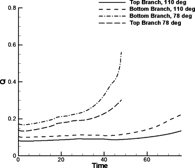
Figure 4 shows Q versus t for two bubbles moving with the same flow conditions, Pbub=6 and Pt=1, through the two bifurcations with different angles. The flow rate in both daughter branches is lower for a bifurcation angle of 110°. These results, as well as the results from previous experimental work,4 suggest that the losses from the wider angle bifurcation make significant changes to the motion of bubbles.
Figure 4.
Flow rates for Pbub=6 and Pt=1 for two different bifurcating angles. The terminations of the graphs correspond to the time it takes the bubble to reach the straight section of the daughter branches. The bubble moving in the bifurcation with angle of 110° moves slower and thus takes longer to reach the straight section.
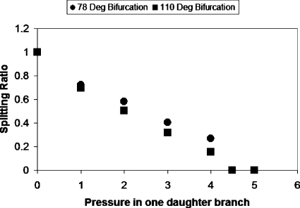
As shown in Fig. 4, there are “wiggles” or small fluctuations in Q as time progresses. During our simulations we varied the time steps in order to discard numerical error from the time stepping method used here. The wiggles in Q as time progresses are due to fluctuations in the contact angle as the meniscuses travel through the bifurcation. The contact angle was observed to vary slightly and was not constant as it slipped through the bifurcation. These fluctuations in the outlet flow rate are mainly due to a variation in the speed of the contact line, similar to a small stick and slip behavior of the contact line. Figure 5 shows the splitting ratio with a driving bubble pressure of 5 for various values Pt (Pb is maintained at zero). As expected, increasing the top daughter channel outlet pressure decreases the splitting ratio. The splitting ratios for the bifurcation with the wider angle again are consistently smaller than the bifurcation with the smaller angle.
Figure 5.
Graph of splitting ratio vs pressure in top daughter branch. The splitting ratio decreases with increasing pressure in the top daughter branch. The bifurcation with larger angle has lower splitting ratio at each daughter channel pressure.
One can speculate that increasing the bifurcation angle will change the behavior of the contact lines both in the front meniscus as well as in the rear meniscus of a bubble as it moves through a bifurcation. Thus, the splitting and lodging behavior of bubbles will depend significantly on the bifurcation angle. This is an important parameter for microchannel design to avoid or, depending on the application, promote bubble entrapment or manipulation of the three phase contact line.
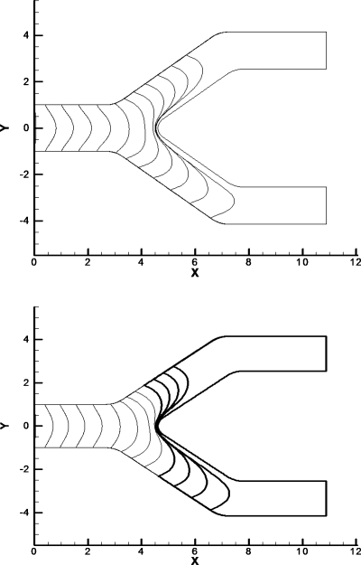
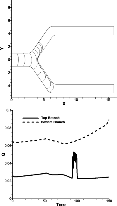
Figure 6 shows examples of bubble interface evolution as a bubble splits in the bifurcation. The net viscous resistance downstream of the bubble decreases as the bubble gets closer to the outlets of the daughter branches. This decrease in viscous resistance will allow the bubble to increase in speed. From Fig. 4 it is observed that the flow rate increases at a high rate when the bubble gets closer to the outlets. This will create an instability in bubble speed, since the longer portion of the bubble will experience less viscous resistance and speed up while the smaller will have lower speeds. This is more noticeable with longer daughter channels. Figure 7 shows the flow rate and interface evolution for a bubble moving through a bifurcation of angle 110° but with longer straight daughter channels. The flow rate for the bottom branch is increasing significantly faster than the flow rate in the top branch. This will cause a splitting instability similar to that observed by Baroud et al.38 in an experimental study for airway reopening in which a semi-infinite plug moved through a bifurcation and to that observed in our previous experiments with finite bubbles.4 Although we did not conduct a stability analysis for Pt=Pb, we note that perturbing the bubble length in a daughter branch does lead to uneven splitting consistent with this instability.
Figure 6.
Bubble evolution for a bifurcating angle of 78°. (Top) This is a bubble evolution with parameters Pbub=6 and Pt=1. (Bottom) This is a bubble evolution with parameters Pbub=4 and Pt=1. The bubble lengths evolve at different rates since the bubble interface in one branch moves faster than the one in the other branch. The branch with less pressure has a longer bubble.
Figure 7.
Bubble evolution and Q for a bifurcation angle of 110°. The parameters for this bifurcation are pressure of 6 driving the bubble and pressure of 2.5 in the top branch. (Top) The bubble favors the bottom branch because it has less opposing pressure than the top branch. (Bottom) Looking at Q vs t we observed that while the flow rate is increasing in the lower branch the top branch remains with constant flow rate. The spike at flow rate at time 91–102 is due to an instability in contact line behavior.
The spike in the upper daughter tube from t=91 to 102 (Fig. 7) is due to contact angle instability. During this time interval, the contact line speed changes from positive to negative. We suspect that if the bubble had a finite length it would probably reverse and go into the lower branch during this time interval or remain static for a period of time. After this time interval the contact line stabilizes and the flow rate is approximately constant. This situation is discussed in more detail below based on velocity and pressure fields. This splitting instability will most likely regulate itself as more bubbles lodge in the microcirculation of tumors, thus increasing the resistance of flow and allowing bubbles to reach previously unoccluded regions.
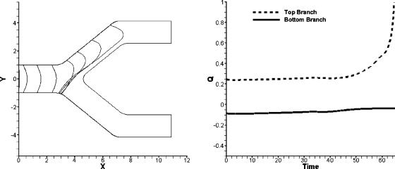
In previous experiments,3, 4 we observed bubbles which began to split but then one of the menisci reversed and the entire bubble eventually entered only one daughter branch of the bifurcation. Values close to the critical driving pressure at which bubbles do not split (Fig. 3) were investigated further, since bubble reversal usually occurred at values close to critical Ca in our previous experiments. The same bubble reversal as the experiments was not expected to occur with a semi-infinite bubble because the conditions for this occurrence are more applicable for a finite bubble. Bubbles will not exhibit reversal until the rear meniscus reaches the carina of the bifurcation and the surface tension prevents the split of the bubble interface. This never happens in the semi-infinite bubble, thus there is no force to reverse the bubble to the other branch. Even though bubbles that began to split did not return even at parameters close to the critical pressure, it was observed that, at daughter pressures higher than the critical pressures in which the bubble went entirely into one branch, the lagging meniscus did reverse while the bubble portion in the branch with lower outlet pressure accelerated. Figure 8 shows the bubble interface evolution with meniscus reversal and the flow rate for the two daughter branches. The beginning of the bubble reversal corresponds to the dramatic increase in flow rate for the top branch.
Figure 8.
Bubble evolution and flow rate for a bubble with parameters Pbub=7 and Pb=8. The left figure shows the bubble evolution and the reversal of the contact line. The right figure shows the flow rates in each daughter channel.
Velocity and pressure field in the surrounding fluid
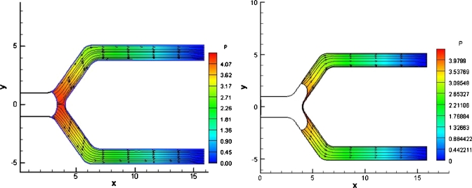
This section will further examine the dynamics of the bubble for some specific flow situations using the velocity and pressure fields of the core fluid in the domain interior. There is a stagnation point in the center of the bifurcation carina for the symmetric outlet pressure case, Pt=Pb (Fig. 9). The pressure is highest at the stagnation point and decreases as one moves away from the center of the carina of the bifurcation. We also observe that pressure increases near the contact line. Experiments by Suzuki and Eckmann39, 40 have shown that bubbles can damage endothelial cells, depending on the time for which bubbles contact the vessel wall, and that adding surfactants minimizes the damage bubbles cause to the endothelial cells. The pressure increase near the contact line could be another contributing fact to the damaging effect of bubbles that travel through the vessels.
Figure 9.
Pressure contours and streamlines for symmetric splitting. The driving bubble pressure is 5. (Left) A stagnation point can be observed in the center of the bifurcation and the flow field looks laminar and symmetric. The pressure is higher near the carina of the bifurcation and near the contact lines.
In the symmetric case all the streamlines are parallel without any recirculation regions. In the cases were Pt and Pb are different the bubble does not split evenly, and in cases where the driving pressure is close or equal to the critical pressure for splitting recirculation regions can be observed. We pay special attention to these cases since these yield results that are significant in relation to the bubble reversal phenomena observed experimentally.3, 4
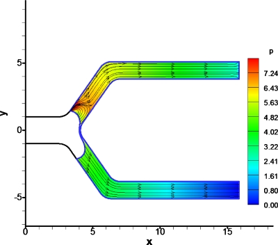
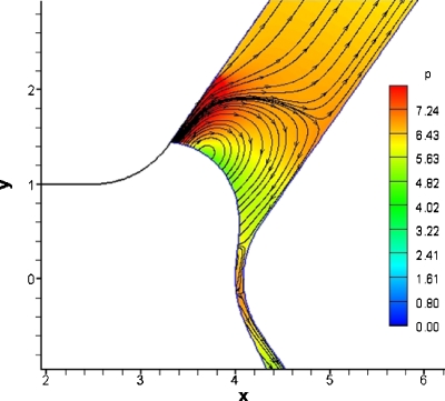
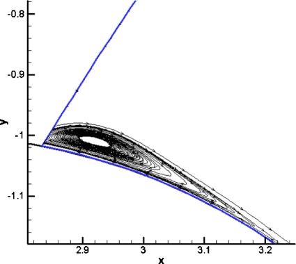
Figure 7 shows an instability in flow rate and contact angle that could indicate the onset of bubble reversal if it were of finite length. We calculated the velocity and pressure fields in the domain interior at t=96, which is inside the range where the flow rate instability occurs (Fig. 10). Figure 11 shows a magnified view of the contact line in the top branch. We observe a recirculation region in front of the meniscus in the upper daughter branch which has a higher outlet pressure. This vortex formation is caused by the instability of the contact line at this time step. From these results we can speculate that bubble reversal might happen if the bubble were finite since a reversal of the bubble will probably cause a similar vortex due to the change of direction of the meniscus. The vortex observed in Figs. 1011 disappears after the contact line stabilizes. Figure 12 shows the same bubble at a later time of t=102 in which the vortex disappears and the pressures near the contact line of the top branch are lower. Figure 2 shows that the pressures between the bubble and the channel wall in the lower daughter branch are high but there is no vortex in this region.
Figure 10.
Pressure and streamlines for t=96. The parameters for this time are Pbub=6 and Pt=2.5. This time corresponds to the unstable behavior of flow rate observed in Fig. 7. The flow is uniform in most of the bifurcation expected in front of the meniscus in the branch with higher pressure which exhibits recirculation.
Figure 11.
Enlarged view of region near the contact line, Pbub=6 and Pt=2.5. We can observe the vortex clearly in front of the bubble and high pressure near the contact line. There is also a small vortex near the carina of the bifurcation, which also has slightly higher pressures than the rest of the flow field.
Figure 12.
Pressure and streamlines for t=102. The vortex disappears and the pressures near the contact line in the branch with higher pressure are lower than at t=96.
The extent of the high pressure region and the size of the vortex near the contact line were investigated with different values of slip length. Slip length was varied arbitrarily from 0.1 to 0.6. The extent of the high pressure region and the size of the vortex increased less than 5% with slip length, but a vortex and a high pressure region was always observed regardless of the slip length value. The pressures exerted by this recirculation region close to the contact line are higher than Pbub−Pt. This suggests that the recirculation region close to the contact line increases the pressure at the vessel wall, which could potentially induce bioeffects in the endothelium.
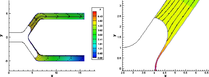
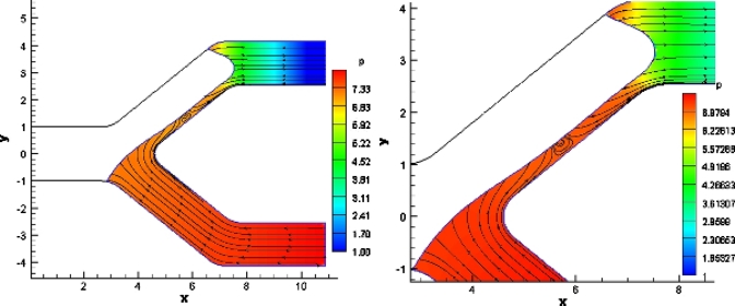
A vortex was also created near the contact line for the parameters Pbub=7 and Pb=8 in which contact line reversal was observed (Fig. 8). Figure 13 shows a small vortex near the contact line at t=55. This vortex is small because the contact line is stopping. Figure 14 shows the pressure contours and streamlines at t=60.4. The streamlines in the lower branch are heading toward the bubble indicating flow reversal, which makes sense since the pressure in the lower branch is higher than the pressure driving the bubble. A vortex is present between the bubble interface and the wall in the upper daughter branch (Fig. 14). This is due to the flow from the lower branch moving toward the upper branch and by some squeezing of the bubble to the wall of the bifurcation. The wall stresses resulting from these vortices may potentially injure the vessel endothelium. On the other hand, these recirculation regions might be beneficial to the mixing of fluids in some microfluidic channel applications.
Figure 13.
Streamline plot of a small vortex in front of a contact line. This is a vortex that is diminishing as the contact line moves backward. Parameters: Pbub=7 and Pb=8.
Figure 14.
Pressure contours and streamlines for Pbub=7 and Pb=8, t=60.4. (Left) The overall flow field. (Right) Magnified view of the vortex in the daughter channel.
Wall shear stress
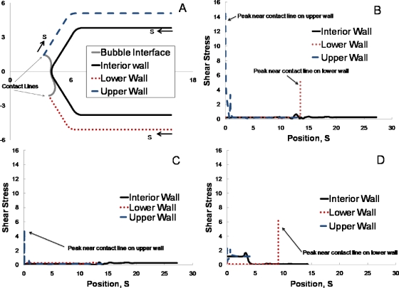
To specifically examine the potential for endothelial cell injury due to shear stress at the vessel wall in addition to pressure, we computed shear stress along the channel wall. Shear stress is plotted as a function of position S along the interior, upper, and lower channel walls in Fig. 15. Figure 15a shows the convention used to measure S for each of these, which corresponds to moving clockwise along the boundary. The wall shear stresses are shown in Figs. 15b, 15c, and Fig. 15d corresponds to the configurations shown in Figs. 101214, respectively. For all of these, the shear stress along the upper and lower walls is highest near the contact lines. Along the interior wall, the shear stress is maximum near the carina of the bifurcation. In Fig. 15b, there is also a local maximum in shear stress along the upper wall near the recirculation region that occurs in front of the bubble nose there (see Fig. 10). This suggests that the oscillating bubble interface and the recirculation region it induces have the potential to impart high stresses on the endothelium for sustained time period during the oscillatory behavior. In Fig. 15d, the shear stress along the interior wall is higher in the upper branch of the bifurcation, downstream from the small recirculation region that occurs between the bubble and the wall in the upper branch (Fig. 14), than is the shear stress in the lower branch. This corresponds to the higher flow in the upper branch compared to the lower branch. The upper branch receives most of the bubble, with little flow into the lower branch (Fig. 14). Correspondingly, the interior wall along the lower branch has a lower shear stress. The lower wall does have a high shear stress near the contact line, as in the other scenarios. In general, the maximum shear stress is the same order as the maximum pressure. The shear stress gradients are high near the bubble contact lines. The stress information provided by this study will guide experiments, where it is challenging to measure stress and stress gradients, to further examine the potential for moving bubbles to induce bioeffects on the endothelium.
Figure 15.
Shear stress along the channel wall. (a) Position S along the wall for the three sections of the wall section, e.g., interior wall, lower wall, and upper wall. S is measured in a clockwise direction for each of these sections. Shear stress vs S is shown for the three wall sections for (b) t=96, Pbub=6, and Pt=2.5 (corresponds to Fig. 10), (c) t=102, Pbub=6, and Pt=2.5 (as in Fig. 12), and (d) t=60.4, Pbub=7, and Pb=8 (as in Fig. 14).
Limitations
Although the current model represents an important first step in computationally modeling the transport of long bubbles through bifurcations, it does have some limitations. It is a two-dimensional model. As the simulations start, the bubble contacts the top and the bottom walls of the parent tube. Extrapolating to the three-dimensional situation, one will expect the bubble to contact the whole circumference of a circular channel. However, as the bubble travels into the daughter tubes, it only contacts one side of the daughter tubes and not both, meaning that in a three-dimensional situation, the bubble no longer contacts the entire circumference of the channel. This might not be the case in all splitting scenarios, even though we have observed partial contact of bubbles as they pass through bifurcations in previous experiments.4 This model could also treat tapered channels or variations in diameter, this type of geometrical situations would be very applicable for the adherence of bubbles in vasculature and will change the motion of the bubble. The motion of the bubble and its adherence is governed by the differences in pressure at each meniscus and the surface tension forces that interact with the fluid and the vessel wall. Changing the geometry of the vessel or channel will affect the shape and motion of the bubble and might create different adherence situations. This model can be extended to consider multiple bifurcations and finite length bubbles, as in our previous experimental studies,4, 5 and we plan to do so in future studies. Computation time will probably be more extensive, but significantly faster than if using other methods such as finite volume or finite element methods. Likewise, this model could be expanded in future work to consider transport of bubbles in tumor vasculature in addition to vessels feeding the tumor.
CONCLUSIONS
The work presented here used a boundary element model to calculate the interface shape and flow field for a semi-infinite bubble contacting the parent channel moving through a bifurcation. It has been shown that the splitting ratio increases with increasing driving bubble pressure while it decreases as the bifurcation angle is increased. Viscous losses at the bifurcation were observed to affect the bubble speed significantly. Bubble reversal and splitting instability observed in our previously reported studies3, 4 were also investigated. Bubble reversal was not clearly observed, but meniscus reversal and creation of recirculation regions due to changes in the velocity field and instabilities were observed, suggesting that if the bubble were finite, reversal or stagnation of one meniscus could be possible. The model presented here also allows us to calculate the velocity profiles, pressures, and stresses associated with a bubble traveling through a bifurcation. It was observed that the pressure and wall shear stresses are higher at the carina of the bifurcation and near the contact line. The cases where recirculation was observed also had high levels of pressure and wall shear stress near the contact line. The results from pressure and wall shear stress will give insight into the forces and stresses cells might experience if bubbles are sliding over the endothelium and will guide experiments to examine possible bioeffects induced by bubble motion. The finding of recirculation regions near the contact line, even in Stokes flow, is relevant to the design of microfluidic cell culture devices that use multiphase flow and to microdevices in which mixing is desired. This first study of semi-infinite bubble transport through channel bifurcations provides new physical insights regarding the behavior of long bubbles in gas embolotherapy, as well as microfluidic and other physiologic situations involving bubbles.
ACKNOWLEDGMENTS
This work was funded by the National Institute of Health (Grant No. R01 EB006476).
References
- Bull J. L., “Cardiovascular bubble dynamics,” Crit. Rev. Biomed. Eng. 33, 299 (2005). 10.1615/CritRevBiomedEng.v33.i4.10 [DOI] [PubMed] [Google Scholar]
- Bull J. L., “The application of microbubbles for targeted drug delivery,” Expert Opinion on Drug Delivery 4, 475 (2007). 10.1517/17425247.4.5.475 [DOI] [PubMed] [Google Scholar]
- Calderon A. J., Fowlkes J. B., and Bull J. L., “Bubble splitting in bifurcating tubes: A model study of cardiovascular gas emboli transport,” J. Appl. Physiol. 99, 479 (2005). 10.1152/japplphysiol.00656.2004 [DOI] [PubMed] [Google Scholar]
- Calderón A. J., Heo Y. S., Huh D., Futai N., Takayama S., Fowlkes J. B., and Bull J. L., “Microfluidic model of bubble lodging in microvessel bifurcations,” Appl. Phys. Lett. 89, 244103 (2006). 10.1063/1.2402898 [DOI] [Google Scholar]
- Eshpuniyani B., Fowlkes J. B., and Bull J. L., “A bench top experimental model of bubble transport in multiple arteriole bifurcations,” Int. J. Heat Fluid Flow 26, 865 (2005). 10.1016/j.ijheatfluidflow.2005.10.002 [DOI] [Google Scholar]
- Eshpuniyani B., Fowlkes J. B., and Bull J. L., “A boundary element model of microbubble sticking and sliding in the microcirculation,” Int. J. Heat Mass Transfer 51, 5700 (2008). 10.1016/j.ijheatmasstransfer.2008.04.050 [DOI] [PMC free article] [PubMed] [Google Scholar]
- Kripfgans O. D., Fabiilli M. L., Carson P. L., and Fowlkes J. B., “On the acoustic vaporization of micrometer-sized droplets,” J. Acoust. Soc. Am. 116, 272 (2004). 10.1121/1.1755236 [DOI] [PubMed] [Google Scholar]
- Kripfgans O. D., Fowlkes J. B., Miller D. L., Eldevik O. P., and Carson P. L., “Acoustic droplet vaporization for therapeutic and diagnostic applications,” Ultrasound Med. Biol. 26, 1177 (2000). 10.1016/S0301-5629(00)00262-3 [DOI] [PubMed] [Google Scholar]
- Kripfgans O. D., Fowlkes J. B., Woydt M., Eldevik O. P., and Carson P. L., “In vivo droplet vaporization for occlusion therapy and phase aberration correction,” IEEE Trans. Ultrason. Ferroelectr. Freq. Control 49, 726 (2002). 10.1109/TUFFC.2002.1009331 [DOI] [PubMed] [Google Scholar]
- Kripfgans O. D., Orifici C. M., Carson P. L., Ives K. A., Eldevik O. P., and Fowlkes J. B., “Acoustic droplet vaporization for temporal and spatial control of tissue occlusion: A kidney study,” IEEE Trans. Ultrason. Ferroelectr. Freq. Control 52, 1101 (2005). 10.1109/TUFFC.2005.1503996 [DOI] [PubMed] [Google Scholar]
- Ye T. and Bull J. L., “Direct numerical simulations of micro-bubble expansion in gas embolotherapy,” J. Biomech. Eng. 126, 745 (2004). 10.1115/1.1824131 [DOI] [PubMed] [Google Scholar]
- Ye T. and Bull J. L., “Microbubble expansion in a flexible tube,” J. Biomech. Eng. 128, 554 (2006). 10.1115/1.2206200 [DOI] [PubMed] [Google Scholar]
- Calderon A. J., “A multiphase flow study of bubbles traveling through bifurcations for a novel gas embolotherapy application,” Ph.D. thesis, University of Michigan, Ann Arbor, MI, 2006. [Google Scholar]
- Eshpuniyani B. and Bull J. L., in Modelling in Medicine and Biology VI, edited by Ursino M., Brebbia C. A., Pontrelli G., and Magosso E. (WIT, Southampton, UK, 2005), p. 331. [Google Scholar]
- Bretherton F. P., “The motion of long bubbles in tubes,” J. Fluid Mech. 10, 166 (1961). 10.1017/S0022112061000160 [DOI] [Google Scholar]
- Gaver D. P., Halpern D., Jensen O. E., and Grotberg J. B., “The steady motion of a semi-infinite bubble through a flexible-walled channel,” J. Fluid Mech. 319, 25 (1996). 10.1017/S0022112096007240 [DOI] [Google Scholar]
- Ratulowski J. and Chang H. -C., “Transport of gas bubbles in capillaries,” Phys. Fluids A 1, 1642 (1989). 10.1063/1.857530 [DOI] [Google Scholar]
- Chang H. K., Delaunois L., Boileau R., and Martin R. R., “Redistribution of pulmonary blood-flow during experimental air-embolism,” J. Appl. Physiol. 51, 211 (1981). [DOI] [PubMed] [Google Scholar]
- Chang H. K., Weber M. E., Thomson J., and Martin R. R., “Hydrodynamic features of pulmonary air embolism: A model study,” J. Appl. Physiol. 51, 1002 (1981). [DOI] [PubMed] [Google Scholar]
- Eckmann D. M., Branger A. B., and Cavanagh D. P., “Gas embolism,” N. Engl. J. Med. 342, 2000 (2000). 10.1056/NEJM200006293422617 [DOI] [PubMed] [Google Scholar]
- Muth C. M. and Shank E. S., “Primary care: Gas embolism,” N. Engl. J. Med. 342, 476 (2000). 10.1056/NEJM200002173420706 [DOI] [PubMed] [Google Scholar]
- Günther A. and Jensen K. F., “Multiphase microfluidics: From flow characteristics to chemical and materials synthesis,” Lab Chip 6, 1487 (2006). 10.1039/b609851g [DOI] [PubMed] [Google Scholar]
- Chang F. M., Sheng Y. J., Cheng S. L., and Tsao H. K., “Tiny bubble removal by gas flow through porous superhydrophobic surfaces: Ostwald ripening,” Appl. Phys. Lett. 92, 264102 (2008). 10.1063/1.2953703 [DOI] [Google Scholar]
- Dijkink R. and Ohl C. D., “Laser-induced cavitation based micropump,” Lab Chip 8, 1676 (2008). 10.1039/b806912c [DOI] [PubMed] [Google Scholar]
- Wu T. H., Gao L. Y., Chen Y., Wei K., and Chiou P. Y., “Pulsed laser triggered high speed microfluidic switch,” Appl. Phys. Lett. 93, 144102 (2008). 10.1063/1.2998395 [DOI] [Google Scholar]
- Yin Z. Z. and Prosperetti A., “A microfluidic ‘blinking bubble’ pump,” J. Micromech. Microeng. 15, 643 (2005). 10.1088/0960-1317/15/3/028 [DOI] [Google Scholar]
- Zwaan E., Le Gac S., Tsuji K., and Ohl C. D., “Controlled cavitation in microfluidic systems,” Phys. Rev. Lett. 98, 254501 (2007). 10.1103/PhysRevLett.98.254501 [DOI] [PubMed] [Google Scholar]
- Lee S., Bull J. L., and Hunt A. J., “Acoustic limitations on the efficiency of machining by femtosecond laser-induced optical breakdown,” Appl. Phys. Lett. 91, 023111 (2007). 10.1063/1.2752990 [DOI] [Google Scholar]
- Halpern D. and Gaver D. P., “Boundary element analysis of the time-dependent motion of a semi-infinite bubble in a channel,” J. Comput. Phys. 115, 366 (1994). 10.1006/jcph.1994.1202 [DOI] [Google Scholar]
- Huh C. and Mason S. G., “The steady movement of a liquid meniscus in a capillary tube,” J. Fluid Mech. 81, 401 (1977). 10.1017/S0022112077002134 [DOI] [Google Scholar]
- Manga M., “Dynamics of drops in branched tubes,” J. Fluid Mech. 315, 105 (1996). 10.1017/S0022112096002352 [DOI] [Google Scholar]
- Greenspan H. P., “Motion of a small viscous droplet that wets a surface,” J. Fluid Mech. 84, 125 (1978). 10.1017/S0022112078000075 [DOI] [Google Scholar]
- Powell C. A., Savage M. D., and Guthrie J. T., “Computational simulation of the printing of Newtonian liquid from a trapezoidal cavity,” Int. J. Numer. Methods Heat Fluid Flow 12, 338 (2002). 10.1108/09615530210433251 [DOI] [Google Scholar]
- Pozrikidis C., Boundary Integral and Singularity Methods for Linearized Viscous Flow (Cambridge University Press, Cambridge, England, 1992). 10.1017/CBO9780511624124 [DOI] [Google Scholar]
- Brebbia C. A. and Dominguez J., Boundary Elements: An Introductory Course (WIT, Southampton, UK, 1992). [Google Scholar]
- Bull J. L., Hunt A. J., and Meyhofer E., “A theoretical model of a molecular-motor-powered pump,” Biomed. Microdevices 7, 21 (2005). 10.1007/s10544-005-6168-6 [DOI] [PubMed] [Google Scholar]
- Karamete B. K., Tokdemir T., and Ger M., “Unstructured grid generation and a simple triangulation algorithm for arbitrary 2-D geometries using object oriented programming,” Int. J. Numer. Methods Eng. 40, 251 (1997). [DOI] [Google Scholar]
- Baroud C. N., Tsikata S., and Heil M., “The propagation of low-viscosity fingers into fluid-filled branching networks,” J. Fluid Mech. 546, 285 (2006). 10.1017/S0022112005007287 [DOI] [Google Scholar]
- Suzuki A., Armstead S. C., and Eckmann D. M., “Surfactant reduction in embolism bubble adhesion and endothelial damage,” Anesthesiology 101, 97 (2004). 10.1097/00000542-200407000-00016 [DOI] [PubMed] [Google Scholar]
- Suzuki A. and Eckmann D. M., “Embolism bubble adhesion force in excised perfused microvessels,” Anesthesiology 99, 400 (2003). 10.1097/00000542-200308000-00022 [DOI] [PubMed] [Google Scholar]


