Abstract
Background
The growing pandemic of diabetes mellitus places a stringent social and economic burden on the society. A tight glycemic control circumvents the detrimental effects, but the prerogative is the development of new more effective tools capable of longterm tracking of blood glucose (BG) in vivo. Such discontinuous sensor technologies will benefit from an unprecedented marked potential as well as reducing the current life expectancy gap of eight years as part of a therapeutic regime.
Method
A sensor technology based on osmotic pressure incorporates a reversible competitive affinity assay performing glucose-specific recognition. An absolute change in particles generates a pressure that is proportional to the glucose concentration. An integrated pressure transducer and components developed from the silicon micro- and nanofabrication industry translate this pressure into BG data.
Results
An in vitro model based on a 3.6 × 8.7 mm large pill-shaped implant is equipped with a nanoporous membrane holding 4–6 nm large pores. The affinity assay offers a dynamic range of 36–720 mg/dl with a resolution of ±16 mg/dl. An integrated 1 × 1 mm2 large control chip samples the sensor signals for data processing and transmission back to the reader at a total power consumption of 76 µW.
Conclusions
Current studies have demonstrated the design, layout, and performance of a prototype osmotic sensor in vitro using an affinity assay solution for up to four weeks. The small physical size conforms to an injectable device, forming the basis of a conceptual monitor that offers a tight glycemic control of BG.
Keywords: CGM, injectable, microtechnology, nanotechnology, osmotic, pressure
Introduction
The onset of the enzyme sensor revolutionized the metabolic control of blood glucose (BG), which previously relied on qualitative urinary blood measurements1 or reflectance meters confined to hospitals.2 Clark and Lyons’ near 50-year-old sensor technology3 enabled the development of portable blood glucose meters (BGM) in which immobilized glucose-specific enzymes interact with electrochemical transducers on a disposable sensor strip. Current detection of BG relies on the same fundamental technology that suffers from limited temperature tolerance,4 oxygen dependency,5 co-existing electroactive compounds,6–8 mass transport control,9 degradation of enzyme activity,10 electrode fouling,11 altitude sensitivity,12 and changing hematocrit level.13 Although remedies have been sought to rectify parts of the challenges mentioned earlier,14,15 the current accuracy of BGMs suffers from a poor performance span of ±5–15%16,17 with 1 in 10 results deviating from the current International Organization for Standardization (ISO) norm.18 Standard protocols sampling blood from the fingertip provide an incomplete picture of the BG related to the number of samplings performed.
Alternative technologies seek to develop indirect pain-free methods ex vivo that bypass the sampling of blood. The most potent optical measurements are based on the adsorption of infrared light,19–21 Raman spectroscopy,22 polarimetry,23 fluorescence particles,24 synthetic films,25 and optical coherence tomography.26 Skin autofluorescence tracks the contents of advanced glycation endproducts in skin and is used to detect diabetes.27 Impedance spectroscopy measures changes in the electrical resistance in the skin as a function of glucose,28 whereas iontophoresis performs transdermal sampling of glucose by the aid of an electrical current.29–30 The ex vivo methods suffer from poor accuracies, individual turbidity variations, pH sensitivity, errors due to motion, moisture, temperature, blood pressure, pulse, and volumetric changes due to osmosis. Implantable sensors based on infrared light,31 fluorescent detection signals,32,33 or viscosity34,35 present promising concepts by performing direct measurements in vivo. This is still a novel field and commercially viable devices have not been realized due to the challenges imposed on their optical detection methods36 or device complexity. In vivo-type measurements for continuous glucose monitoring (CGM) are currently based on transdermal cannulas connected to electrochemical sensors from an external reader.37,38 The lifetime is dependent on enzyme stability, and continuous use requires frequent daily recalibrations39 before it stops working after a few days.40 The combination of size, complexity, low sensitivity, and motion impairment does not permit long-term automatic continuous-surveillance devices to be made.
Osmotic BG-sensing represents a novel sensing technology that contrasts prior art by being inherently simple and extremely power-conservative—a prerogative enabling a sensor system with the aid of micro- and nanotechnology. It does not consume reagents or generate any (toxic) waste products that may perturb the accuracy and sensitivity of the measurement. Chemically inert materials secure long lifetimes for a module small enough for insertion under the skin without the aid of surgery, causing no disruption to active life from its portable and unobtrusive nature.
This article presents work on the implantable osmotic CGM device invented by Lifecare AS (Bergen, Norway) and their national and international research partners.41–43 The results highlight efforts in developing ultrathin nano-porous membranes, a sensor control system, an inductive power supply, and a reader; packaging the implant; and monitoring the immune system response based on a serum model. Initial tests showing the sensitivity toward changing glucose concentrations as well as stability with time will be shown.
Methods
CGM Design
Implant
The CGM consists of a microfabricated pill-shaped implant and an external reader. The materials are referred to in Table 1. The sensing principle of the implant is based on the macromolecular complex that is formed between lectin, concanavalin A (Con A), and dextran (a long-chained polysaccharide) at low glucose concentrations. The Con A possesses an affinity toward glucose, and the equilibrium is perturbed by glucose binding to the lectin, triggering a dissociation of dextran that is proportional to the increase in glucose. The net particle change of free dextran gives rise to an osmotic pressure as a result from water diffusing down its own concentration gradient through a nanoporous (semipermeable) membrane that separates the affinity assay from the external environment (Equation 1):
| (1) |
The pressure, Π (bar), is expressed as the concentration of dissolved components; c (solute); adjusted for the van’t Hoff factor, i; the universal gas constant, R (0.08314 L·bar·mol-1·K-1); and absolute temperature, T. This process is reversible and the selectivity of the affinity assay makes the sensor less susceptible to interference from other metabolic agents such as lactate, amino acids, and triglycerides that are present in blood.
Reader
The data processing and presentation is performed by an external reader. The inductive powering and telemetry interface between the reader and the implant takes advantage of the magnetic component of the radiation spectrum that attenuates less in physiological media and secures a short transmission distance preventing eavesdropping by a third party. The implant resides as a passive device that is activated when a measurement is made, and will reside in subcutaneous adipose tissue within 7 mm of the skin surface.
Membrane
The in vitro prototype was based on anodic aluminum oxide (AAO) membranes of 1 µm film thickness offering a porosity of 15% and a pore size of 4–6 nm corresponding to a molecular weight cut-off (MWCO) of approximately 50 kDa (Synkera Technologies Inc., Longmont, CO). This retained the affinity assay components (80–108 kDa), whereas glucose (180 Da) flowed freely through the membrane. Thin film silicon (Si) membranes targeting an improved porosity and reduced film thickness were designed in house, based on protocols from the Si microfabrication industry.
Test & Validation
All materials, chemicals, and reagents used were purchased from Sigma-Aldrich Inc. (St. Louis, MO) unless otherwise stated (Table 1). Con A type IV and dextran 80 were dissolved in 10 mM Trizma buffer at a concentration of 8% (3 mM) and 4% (0.5 mM) respectively. The buffer contained calcium chloride (CaCl2) and manganese chloride (MnCl2) (both 10 mM) used to activate the sugar-binding properties of Con A; sodium choloride (NaCl) (150 mM), which balanced out the osmotic pressure of the solution; and glucose (40 mM), which reduced the viscosity during mixing.The solution was adjusted to pH 7.4 by administering sodium hydroxide (50 mM) at a rate of 10 ml/min with a peristaltic pump (Watson-Marlow, Wilmington, MA). Test solutions of glucose were then dissolved in 10 mM Trizma (containing 10 mM CaCl2, 10 mM MnCl2, and 150 mM NaCl) at concentrations of 2, 5, 10, 20, 30, and 40 mM (corresponding to 36, 90, 180, 360, 540, and 720 mg/dl), and used to calibrate the affinity assay at ambient room temperature. Each measurement was performed over 24 hours, and repeated three times. Albumin (1 mM) was used to investigate the stability with time over a period of one week in order to pinpoint pressure variations with respect to confluence, temperature, and barometric pressure. The sensor was calibrated using an external pneumatic source.
Table 1.
Materials and Technical Data of the Continuous Glucose Monitor
| Materials | ||
| Transducer | 2 × 2 mm2, diff, 1 bar | MS761, Intersema, CH |
| Membrane | 2 × 2 mm2SiO2/Si diea AAO in prototypes | In-house thin film Synkera Ltd., US |
| Carrier | Type 951 LTCC | |
| Sealant | Type 353ND4 (epoxy) 3140 (silicone) | Epotek, US Dow Corning, US |
| Encapsulation | Araldite 2020 (epoxy) | Huntsman, US |
| SMC capacitors | Ceramic type 0402 | Farnell, US |
| Diblock copolymer | PS-P2VPa | Polymer Standards, DE |
| Affinity assay | Con A type IV, C-2010 Dextran 80, O-0892 Trizma buffer, T-7693 | Sigma-Aldrich, US Sigma-Aldrich, US Sigma-Aldrich, US |
| Albumin | Bovine serum, A-9418 | Sigma-Aldrich, US |
| Implant | ||
| Length × diameter | 8.7 × 3.6 mm | |
| Weight | 0.15 g, buoyancy less than water | |
| System controller | 48 pad ASICa, 1 × 1 mm2, 90 nm STM CMOSa, 1.7 μW | |
| Sensors | (1) Osmotic pressure (2) Temperature (integrated) | |
| Membrane area | 1 × 1 mm2 | |
| Chamber volume | 0.72 μl | |
| Maximum pressure | 1 bar (1000 hPa) above ambient | |
| Dynamic range | 36–720 mg/dl (glucose) | |
| Sensitivity | 2.3 mg/dl | |
| Resolution | ±16 mg/dl | |
| Time constant, τ (63% of signal change) | 40 minutes @ ∼Δ 55 mg/dl (36–90 mg/dl) 2.5 hours @ ∼Δ 685 mg/dl (36–720 mg/dl) | |
| Antenna | Spiral coil, 4 layer, 3 × 7.3 mm2, 1.22 μH, Q factor = 11 | |
| Communication | Load modulated NFC | |
| Power supply | Inductive coupled, 76–625 μW, 2.5 VDCat 13.56 MHz | |
| Power consumption | 76 μW | |
| Service lifetime | 4 weeks | |
| Reader | ||
| Transmission frequency | 13.56 MHz | |
| Transmission distance | <7 mm | |
| Power transfer efficiency | 0.6% @ 7 mm | |
| Power supply | 3.2–4.5 VDC, 3 × SR/LR44, 175 mAh | |
| Antenna | Coil, 2 × 3 layer, 19 mm, 0.56 μH, Q factor = 22 | |
| Power consumption | 1) 50–110.0 mW (transmission) 2) 10 μW (standby) | |
| Sampling interval | 5 seconds every 5 minutes | |
| Battery lifetime | 2 weeks | |
| SiO2, silicon dioxide; PS-P2VP, polystyrene-block-poly(2-vinylpyridine); ASIC, application-specific integrated circuit; STM, STMicroelectronics; CMOS, complementary metal-oxide semiconductor; Q, quality; NFC, near field communication | ||
The implant materials were subject to human serum studies in order to assess their biocompatible properties using the complement system as a model.44 The sample was incubated with human serum at 37 °C for 30 minutes. The plates (materials) were then washed with phosphate buffered saline with Tween 20 prior to measuring the deposition of C5b-9 terminal complement complex (TCC) on the surface of the materials. The specificity of TCC deposition on the material surface was estimated using an isotype control antibody, immunoglobulin G2a.
Results
CGM Design
Implant
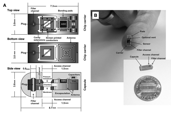
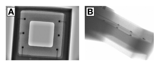
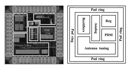
The osmotic pressure sensor (Figure 1) is built into a carrier of low temperature cofired ceramic (LTCC) consisting of 13 (90–130 µm thick) layers of a glass-ceramic composite. Conductors and vias are screen printed onto individual layers with gold paste to form the electrical circuitry, prior to laser cutting or punching to form the desired microchannels and cavities. The layers are then stacked on top of each other and laminated at 1200 psi prior to sintering at 850 °C for seven hours in a cofiring process. The 2 × 2 mm2 large pressure transducer is mounted face down by thermocompression flip-chip bonding (325 °C for 10 s, at 2.8 N) and sealed to the carrier with epoxy resin sealant (Epotek 353ND4) cured at 100 °C for 10 minutes (Figure 2). Cavity extensions in all four corners of the recess assist the minute dispensing of sealant. Likewise, a 2 × 2 mm2 large membrane chip incorporating a nanoporous membrane of 1 × 1 mm2 was attached face down on the reverse side and sealed to the carrier using the same sealant. The 0.5 mm deep and 1.2 × 1.2 mm2 large reference chamber was filled with the affinity assay solution once the sensor assembly was completed. Access was made through an integrated 80 × 80 µm2 microchannel, and liquid translocation was facilitated by vacuuming through the membrane. Fluid access was permitted through a separate filler channel, subsequently sealed with a plug once the filling was completed. The application-specific integrated circuit (ASIC) that powered the sensor and sampled the signal for data processing was fabricated as a 48-pin 1 × 1 mm2 large Si die following the STM 90-nm complementary metal oxide semiconductor process (STMicroelectronics, Geneva, Switzerland) (Figure 3) with circuits running in the subthreshold regime.44 Three 0.4 mm × 0.2 mm surface mount device capacitors were needed for the powering and telemetry interface. The antenna was integrated in the LTCC substrate from the reverse side as a four-layer spiral coil with a maximum extent of 3 × 7.3 mm2, thus offering a self inductance of 1.22 µH and a Q (quality) factor of 11. The assembled device was encapsulated by a low-viscosity epoxy resin (Araldite 2020), which cured at room temperature for 48 hours to a hard chemically resistant polymer. The access and filler channels were drilled out after curing. Small polypropylene cups attached with 3140 silicone rubber protected the surface from the resin, and were subsequently removed after drilling. The completed implant measured 3.6 × 8.7 mm, weighted 0.15 g, and had a total power consumption of 76 µW at 2.5 VDC.
Figure 1.
Computer-aided design depicting the architecture of the sensor implant (A). The sensor chip, incorporating a differential pressure transducer located at the front, followed by the ASIC (including temperature compensation) and components of the inductive powering and telemetry interface. The membrane and the inductive coil antenna are assembled on the reverse side. The whole unit is encapsulated in epoxy resin (Araldite 2020), with a filler channel enabling injection of the aqueous osmotic active solution prior to operation. (B) Assembled prototype carrier and capsule. An optional venting channel assisted filling in early versions.
Figure 2.
X-ray image of the pressure transducer attached face down on the LTCC by flip-chip thermocompression bonding, as seen from above (A) and at an angle (B). This inspection offers the only means to assess the quality of the bond by looking for open circuits and poor connections (visible as thin white lines).
Figure 3.
Layout plot of the 1 × 1 mm2ASIC control chip (left), and the associated explanatory diagram (right). The sensor data was sampled and converted for transmission on a serial digital wireless link using a pulse density modulation. The low sampling rate (one per five minutes) combined with the low power allowance inspired the use of time domain encoding in which the intervals between digital signals were used to encode analog data without the need for a full analog to digital conversion.
Reader
The external reader incorporated the active end of a 13.56 MHz powering and telemetry interface (transmitter) with a six-turn antenna of 19 mm diameter offering an inductance of 0.56 µH and a Q factor of 22. The transmitter powers the ASIC and the sensor, which in turn sends back a coded signal proportional to the osmotic pressure through a process known as load modulation. The reader calculates the osmotic pressure as a voltage signal and translates this data into the accompanying BG value. The induced field strength fades rapidly with the distance from the transmitter antenna. When the transmitter power level is matched to the power consumption of the implant at a distance of 7 mm, the induced field at 5 cm is 0.25 A/m, which is 30 times lower than the maximum limit of ISO 14443 compliant radio-frequency identification devices. Equipped with a microcontroller, the reader can be shut down between the power transfer cycles and reactivated by a micropower timer (10 µW). The power transfer efficiency was measured to 0.6% at a distance of 7 mm, whereas the attenuation in physiological media was 15%. The interference from near field communication mobile phones running at the same operating frequency was negligible if the distance to the implant was more than 10 cm. The readout was presented as a hexadecimal display with 256 increments (8 bit) offering a resolution of 2.3 mg/dl.
Membrane
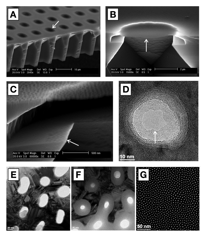
Membranes of 1 × 1 mm2area, 100 nm thickness, equipped with pores of 5 nm (MWCO of 50 kDa), a pore density of 40%, a pressure tolerance of 1 bar, and chemical inertness in physiological media,45will reduce the current diffusion barrier by a factor of 100, yielding a subsequent decrease in the response time. The fabrication protocol has been described in prior art,46realizing a thin film membrane of 30 nm silicon nitride clad on both side by 15 nm amorphous silicon (aSi). The 5 µm circular suspended membrane elements (6400 in total) were engineered to sustain a pressure of 10 bar (Figure 4A and 4B), whereas the support beams would sustain a lower pressure. Visual inspection could thus discriminate a defect membrane from working ones, by permitting the 1 × 1 mm2 structure to fail before the individual elements. The membrane was made porous (Figure 4C) by first depositing a 25 nm sacrificial layer of silicon dioxide (SiO2) prior to casting a mask layer of polystyrene-block-poly(2-vinylpyridine) (PS-P2VP) diblock copolymer in a block ratio of 25 kDa PS and 27 kDa P2VP dissolved in m-xylene (0.5% w/w) at a spin speed of 5000 rpm. The resulting PS micelles were opened up with ethanol, and pores were etched into the SiO2 by a fluorine gas. Subsequent etching through the underlying thin film membrane with a chlorine gas removed the sacrificial SiO2 layer. Direct inspection through a transmission electron microscope visualized a tapered etching profile where the entry hole of 30 nm diameter reduced to an exit hole of approximately 15 nm (Figure 4D). The pores were shrunk further by oxidizing the two layers of aSi to SiO2 in a furnace at 850 °C for 60 minutes (Figure 4E and 4F). Recent work has demonstrated membranes down to the 5 nm level (Figure 4G).
Figure 4.
Scanning electron microscope image showing the membrane support structure (A) with 5 µm suspended (free standing) membrane elements (arrow). (B) Cross section of individual element (arrow) showing the porous nature of the membrane (C) visible through the indentations left on the nearby silicon shelf (arrow) due to the etching gas penetrating the membrane. Nanopore (D) visible through a transmission electron microscope. Pore shrinking protocol illustrating the oxidation of larger pores (E) triggering a size reduction of more than 50% (F), down to the current limit of 5 nm (G).
Test & Validation
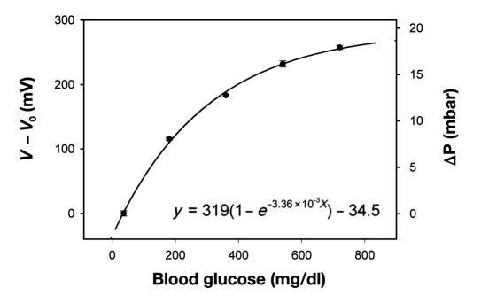
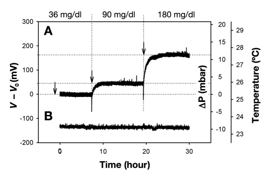
Performance was tested out on a discrete sensor with a direct communication link. Pneumatic calibration identified the relationship between applied pressure and the voltage signal [∫mBar(mV) = mV/14.42, R2= 0.99]. The affinity assay displays an exponential rise in osmotic pressure as a function of glucose (Figure 5). The sensitivity decreases as the solutions become more saturated at increasing glucose concentrations, suggesting that the osmotic sensor should be particularly suitable to detect hypo- and hyperglycemic events (Figure 6). The noise band (6 σ) of 20 mV determines the average resolution (±3 σ) to ±16 mg/dl between 36 and 180 mg/dl. The absolute response time depends on the incremental concentration changes and ranged from 3 hours (Δ55 mg/dl)to 12 hours (Δ685 mg/dl). The time constant τ (63% of absolute signal) was measured to be 40 minutes and 2.5 hours respectively. The current device would at best be able to detect an average level of the blood sugar, or trends predicting if the blood sugar is on the rise or decrease. This sensor is still very much a research object, and thus would need to be improved in order to detect the absolute glucose level at any given moment. Our target is a response time of 1 minute.
Figure 5.
Calibration curve showing the affinity assay response to changing glucose concentrations from 36 to 720 mg/dl (n = 3) at room temperature. The sensor was cycled between 40 mM – 2 mM – 40 mM – 2 mM – 40 mM – 2 mM, in order to obtain three consecutive measurements, and where the 2 mM was consequently replaced with 10, 20, 30, and 40 mM in one continuous trial. The small error bars shows that any hysteresis effects are negligible. The corresponding osmotic pressure was calculated from sensor calibration using an external pneumatic source.
Figure 6.
Sensor response (A) to changing glucose values within the normal physiological range spanning subhypoglycemia at 36 mg/dl, normal blood glucose of 90 mg/dl, to hyperglycemia at 180 mg/dl. The negative spikes associated with the transition from lower to higher glucose levels can be ascribed to the inherent diffusion barrier poised by the membrane delaying the permeation of glucose into the sensor. Temperature (B) was maintained at a stable ambient of 23.4 °C.
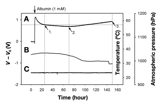
Investigations of the sensor drift circumvented the affinity assay by using albumin (65 kDa) of comparable size to Con A and dextran as a model compound (Figure 7). A small leakage was observed during the first 10 hours (Figure 7A) before the pressure stabilized to a steady drift of -0.13 mbar/h followed by a steady increase of 0.22 mbar/h thereafter. The differential nature of the pressure transducer made it impervious toward atmospheric pressure variations (Figure 7B) whereas on board electronics compensated for any temperature fluctuations (Figure 7C).
Figure 7.
Sensor response (A) using albumin (1 mM) as a model compound over a period of one week. Following an exponential decay believed to be the loss of albumin through the sensor sealant, the signal maintains a steady drift (arrow 1) until halfway through the measurement period (arrow 2), followed by a positive drift until the end of the experiment. The drift can be ascribed to the minute diffusion of water into the epoxy resin used as the sealant of the pressure transducer, hence causing it to swell and thereby exerting pressure/strain on the transducer chip. The signal was impervious to ambient atmospheric pressure (B) and temperature variations (C).
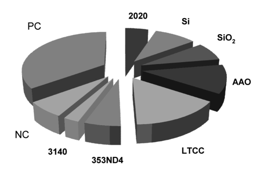
Serum studies (Figure 8) revealed that Araldite 2020 exhibited a comparable response to the negative control (NC) of PS. Two of the three membrane materials, Si and AAO, exhibited a more positive response than the NC (SiO2comparable), suggesting that additional passivation may be required to prevent unwanted immunological reactions. The carrier materials of DuPont 951 (LTCC), exhibited a larger response than the NC, but will be masked by the encapsulation. The United States Pharmacopeia class IV tested Epotek 353ND4 exhibited a comparable response to the NC, whereas the silicone 3140 had a lower response. No nonspecific complement activity was recorded.
Figure 8.
TCC deposition (% of total) on the surface of material candidates of the CGM implant (n = 20). Three of the seven materials exhibited a larger response than the negative control (NC) suggesting that the immunological response would require modulation prior to implantation of these target materials. None of the materials exhibited a larger response than the heat-aggregated immunoglobulin G used as a positive control (PC).
Discussion
Poor ventilation of reactants and (waste) products remains a challenge in developing thin film membranes with pores below 15 nm. A reduced etching rate in the pores triggers an increase in etching time that places a strain on the mask, which eventually breaks down and damages the membrane below. Premature termination of the etching process saves the membrane, at the expense of the pores not penetrating throughout. Future work will focus on inherently porous materials, as well as thinning down the existing AAO membranes.
The osmotic pressure generated by the albumin and the affinity assay was three times higher than the predicted values at an ambient temperature of 23.4 °C (Equation 1). Minute leakages in the sensor may result in a pressure drop through the narrow 1/16-inch polytetrafluoroethylene pneumatic tubes feeding air into the sensor through a 25G (0.5 mm) needle. Thus, the sensor output would be recorded at a lower pressure than the manometer reading. Using the 75 mbar signal from the albumin as a reference (1 mM computes to 24.6 mbar at 23.4 °C), the osmotic pressure of the affinity assay would reduce to 5.6 mbar, comparable to 50% of the available dextran (0.228 mM) being dissociated in the presence of 720 mg/dl glucose. Future work will enable direct hydrostatic pressure calibrations using noncompressible liquid media. The initial confluence of albumin was most likely a result of a leaky seal that with time (10+ hours) became clogged with albumin, preventing any further leakage.
Changes in the affinity assay response with time may explain the larger signal at 180 mg/dl glucose (Figure 6B)compared to the calibration graph (Figure 5). The calibration commenced three weeks prior to sensor measurements, and further investigations will track the time-dependent drift of the affinity assay. The response time of more than three hours is chiefly ascribed to the diffusion barrier posed by the membrane, since the 0.5 mm deep reference chamber should equilibrate molecular species within two minutes (diffusion coefficient = 10-9m2/s).47
Challenges imposed in solving the host response dynamics with synthetic implants have been the focus of considerable efforts due to the adverse inflammatory responses that are evident following implantation.48–50 The initial study on complement activity corroborates this challenge (Figure 8), and future work will seek to narrow the application from challenges surrounding a general implant to key immune system interactions between the tissue and the membrane. The materials were chosen due to their inherent chemical stability that would resist harsh sterilization effects such as autoclaving, ethanol, or plasma radiation, as well as corrosion resistance in the body. This was our primary concern. Secondary was the choice of nonpoisonous materials that best implemented the functional needs of the sensor. If the materials chosen in a functional sensor cannot be replaced, then the natural step is to modify the surface of the material to better conform to a desired immune response. Experimental polymeric coatings51,52 and the sustained release of antiinflammatory agents combined with tunable, stimuli-responsive materials53,54 should act favorably in maintaining such a reduced inflammatory response. Cytotoxicity will be investigated using standard models.55,56 The small dimensions of the device will significantly reduce the trauma imposed at the implantation site and thereby promote the regeneration of damaged microvasculature reconstituting original architecture without the formation (or the reduced formation) of scar tissue. This is an ongoing iterative process, and a thorough assessment of the biocompatible materials in vitro forms the basis of a full additional manuscript that cannot be incorporated into the present one.
Conclusions
Current studies have demonstrated the design, layout, and performance of the osmotic sensor in vitro using an affinity assay solution for up to four weeks. The observed drift in the affinity assay sensitivity and sensor signal with time will be assessed in order to improve device performance. Investigations on the immune system response suggest that surfaces of silicon and ceramic materials may require additional modifications to prevent adverse inflammatory responses in vivo. The small physical size conforms to a device that can be inserted under the skin by injection, and thereby forms the basis of a conceptual monitor offering a tight glycemic control of blood glucose.
Acknowledgements
The authors are indebted to the technical staff and colleagues at Vestfold University College, University of Oslo, Centre Suisse d’Electronique et Microtechnique SA, and VTT Technical Research Centre of Finland, in order to realize this work. The authors would like to thank Dr. Simon Kuenzi for valuable discussions on the affinity assay, Stein Kristiansen at the Norwegian Meteorological Institute for ambient atmospheric pressure data, and Synkera Technologies Inc. for use of their prototype membranes.
Abbreviations
- aSi
amorphous silicon
- AAO
anodic aluminum oxide
- ASIC
application-specific integrated circuit
- BG
blood glucose
- BGM
blood glucose meter
- CaCl2
calcium chloride
- CGM
continuous glucose monitoring
- Con A
concanavalin A
- ISO
International Organization for Standardization
- LTCC
low temperature cofired ceramic
- MnCl2
manganese chloride
- MWCO
molecular weight cut-off
- NaCl
sodium chloride
- NC
negative control
- Q
quality
- Si
silicon
- SiO2
silicon dioxide
- TCC
terminal complement complex
- σ
standard deviation
References
- 1.Dufaitre-Patouraux L, Vague P, Lassmann-Vague V. History, accuracy and precision of SMBG devices. Diabetes Metab. 2003;29(2):S7–S14. [PubMed] [Google Scholar]
- 2.Clemens AH. USA: Miles Laboratories, Inc.; 1971. Reflectance meter. In: patent US, vol. 3,604,815. [Google Scholar]
- 3.Clark LC, Jr, Lyons C. Electrode systems for continous monitoring in cardiovascular surgery. Ann N Y Acad Sci. 1962;102:29–45. doi: 10.1111/j.1749-6632.1962.tb13623.x. [DOI] [PubMed] [Google Scholar]
- 4.Fjield T, Higgins MJ. USA: Edwards Lifesciences Corporation; 2009. Monitoring and compensating for temperature-related error in an electrochemical sensor. In: Edited by patent US. [Google Scholar]
- 5.Kurahashi K, Maruta H, Usuda Y, Ohtsuka M. Influence of blood sample oxygen tension on blood glucose concentration measured using an enzyme-electrode method. Crit Care Med. 1997;25(2):231–235. doi: 10.1097/00003246-199702000-00006. [DOI] [PubMed] [Google Scholar]
- 6.Endo H, Yonemori Y, Hibi K, Ren H, Hayashi T, Tsugawa W, Sode K. Wireless enzyme sensor system for real-time monitoring of blood glucose levels in fish. Biosens Bioelectron. 2009;24(5):1417–1423. doi: 10.1016/j.bios.2008.08.038. [DOI] [PubMed] [Google Scholar]
- 7.Heller A, Feldman B. Electrochemical glucose sensors and their applications in diabetes management. Chem Rev. 2008;108(7):2482–2505. doi: 10.1021/cr068069y. [DOI] [PubMed] [Google Scholar]
- 8.Emr SA, Yacynych AM. Use of polymer films in amperometric biosensors. Electroanalysis. 1995;7(10):913–923. [Google Scholar]
- 9.Reach G, Wilson GS. Can continuous glucose monitoring be used for the treatment of diabetes. Anal Chem. 1992;64(6):381A–386A. doi: 10.1021/ac00030a001. [DOI] [PubMed] [Google Scholar]
- 10.Valdes TI, Moussy F. In vitro and in vivo degradation of glucose oxidase enzyme used for an implantable glucose biosensor. Diabetes Technol Ther. 2000;2(3):367–376. doi: 10.1089/15209150050194233. [DOI] [PubMed] [Google Scholar]
- 11.Tang Z, Louie RF, Lee JH, Lee DM, Miller EE, Kost GJ. Oxygen effects on glucose meter measurements with glucose dehydrogenase- and oxidase-based test strips for point-of-care testing. Crit Care Med. 2001;29(5):1062–1070. doi: 10.1097/00003246-200105000-00038. [DOI] [PubMed] [Google Scholar]
- 12.Bilen H, Kilicaslan A, Akcay G, Albayrak F. Performance of glucose dehydrogenase (GDH) based and glucose oxidase (GOX) based blood glucose meter systems at moderately high altitude. J Med Eng Technol. 2007;31(2):152–156. doi: 10.1080/03091900600861590. [DOI] [PubMed] [Google Scholar]
- 13.Forrow NJ, Bayliff SW. A commercial whole blood glucose biosensor with a low sensitivity to hematocrit based on an impregnated porous carbon electrode. Biosens Bioelectron. 2005;21(4):581–587. doi: 10.1016/j.bios.2004.12.011. [DOI] [PubMed] [Google Scholar]
- 14.Wang J. Glucose Biosensors: 40 years of advances and challenges. Electroanalysis. 2001;13(12):983–988. [Google Scholar]
- 15.Wang J. In vivo glucose monitoring: towards ‘Sense and Act’ feedback-loop individualized medical systems. Talanta. 2008;75:636–641. doi: 10.1016/j.talanta.2007.10.023. [DOI] [PubMed] [Google Scholar]
- 16.Yamazaki T, Kojima K, Sode K. Extended-range glucose sensor employing engineered glucose dehydrogenases. Anal Chem. 2000;72(19):4689–4693. doi: 10.1021/ac000151k. [DOI] [PubMed] [Google Scholar]
- 17.Weinstein RL, Schwartz SL, Brazg RL, Bugler JR, Peyser TA, McGarraugh GV. Accuracy of the 5-Day FreeStyle Navigator Continuous Glucose Monitoring Systemml: comparison with frequent laboratory reference measurements. Diabetes Care. 2007;30(5):1125–1130. doi: 10.2337/dc06-1602. [DOI] [PubMed] [Google Scholar]
- 18.Hoedemaekers CW, Klein Gunnewiek JM, Prinsen MA, Willems JL, Van der Hoeven JG. Accuracy of bedside glucose measurement from three glucometers in critically ill patients. Crit Care Med. 2008;36(11):3062–3066. doi: 10.1097/CCM.0b013e318186ffe6. [DOI] [PubMed] [Google Scholar]
- 19.Koschinsky T, Heinemann L. Sensors for glucose monitoring: technical and clinical aspects. Diabetes Metab Res Rev. 2001;17(2):113–123. doi: 10.1002/dmrr.188. [DOI] [PubMed] [Google Scholar]
- 20.Kajiwara K, Uemura T, Kishikawa H, Nishida K, Hashiguchi Y, Uehara M, Sakakida M, Ichinose K, Shichiri M. Noninvasive measurement of blood glucose concentrations by analysing Fourier transform infra-red absorbance spectra through oral mucosa. Med Biol Eng Comput. 1993;31(Suppl):S17–S22. doi: 10.1007/BF02446645. [DOI] [PubMed] [Google Scholar]
- 21.Burmeister JJ, Chung H, Arnold MA. Phantoms for noninvasive blood glucose sensing with near infrared transmission spectroscopy. Photochem Photobiol. 1998;67(1):50–55. [PubMed] [Google Scholar]
- 22.Enejder AM, Scecina TG, Oh J, Hunter M, Shih W, Sasic S, Horowitz V, Feld MS. Raman spectroscopy for noninvasive glucose measurements. J Biomed Opt. 2005;10(3):031114. doi: 10.1117/1.1920212. [DOI] [PubMed] [Google Scholar]
- 23.Ansari RR, Böckle S, Rovati L. New optical scheme for a polarimetric-based glucose sensor. J Biomed Opt. 2004;9(1):103–115. doi: 10.1117/1.1626664. [DOI] [PubMed] [Google Scholar]
- 24.Badugu R, Lakowicz JR, Geddes CD. Fluorescence sensors for monosaccharides based on the 6-methylquinolinium nucleus and boronic acid moiety: potential application to ophthalmic diagnostics. Talanta. 2005;65(3):762–768. doi: 10.1016/j.talanta.2004.08.003. [DOI] [PMC free article] [PubMed] [Google Scholar]
- 25.Pringsheim E, Terpetschnig E, Piletsky SA, Wolfbeis OS. A poly-aniline with near-infrared optical response to saccharides. Adv Mat. 1999;11(10):865. [Google Scholar]
- 26.Larin KV, Eledrisi MS, Motamedi M, Esenaliev RO. Noninvasive blood glucose monitoring with optical coherence tomography: a pilot study in human subjects. Diabetes Care. 2002;25(12):2263–2267. doi: 10.2337/diacare.25.12.2263. [DOI] [PubMed] [Google Scholar]
- 27.Ediger M, Maynard JD. Noninvasive optical detection of impaired glucose tolerance: a comparison against FPG and A1C. Rev of Endocrinology. 2007 Jun;:62–64. [Google Scholar]
- 28.Caduff A, Hirt E, Feldman Y, Ali Z, Heinemann L. First human experiments with a novel non-invasive, non-optical continuous glucose monitoring system. Biosens Bioelectron. 2003;19(3):209–217. doi: 10.1016/s0956-5663(03)00196-9. [DOI] [PubMed] [Google Scholar]
- 29.Sieg A, Guy RH, Delgado-Charro MB. Electroosmosis in transdermal iontophoresis: implications for noninvasive and calibration-free glucose monitoring. Biophys J. 2004;87(5):3344–3350. doi: 10.1529/biophysj.104.044792. [DOI] [PMC free article] [PubMed] [Google Scholar]
- 30.Tamada JA, Bohannon NJ, Potts RO. Measurement in glucose in diabetic subjects using noninvasive transdermal extraction. Nat Med. 1995;1(11):1198–1201. doi: 10.1038/nm1195-1198. [DOI] [PubMed] [Google Scholar]
- 31.Yu YZ, Crothall KD, Jahn L, Destefano M. Laser diode applications in a continuous blood glucose sensor. SPIE proceedings series. 2003;4996:268–274. [Google Scholar]
- 32.Colvin AE, O’Connor CJ, DeHennis AD. USA: Sensors for Medicine and Science, Inc.; 2007. Optical-based sensing devices. In: US patent 7,308,292. [Google Scholar]
- 33.Ballerstadt R, Schultz JS. A fluorescence affinity hollow fiber sensor for continuous transdermal glucose monitoring. Anal Chem. 2000;72(17):4185–4192. doi: 10.1021/ac000215r. [DOI] [PubMed] [Google Scholar]
- 34.Beyer U, Fleischer A, Kage A, Haueter U, Ehwald R. Calibration of the viscometric glucose sensor before its use in physiological liquids—compensation for the colloid-osmotic effect. Biosens Bioelectron. 2003;18(11):1391–1397. doi: 10.1016/s0956-5663(03)00067-8. [DOI] [PubMed] [Google Scholar]
- 35.Kuenzi S. Lausanne: EPFL; 2007. Implantable glucose sensor: an approach based on a rotating microviscometer combined with a sensitive liquid containing dextran and concanavalin A. [Ph.D. Thesis] [Google Scholar]
- 36.Colvin AE, Zerwekh PS, Lesho JC, Lynn RW, Lorenz CR, O’Connor CJ, Walters SJ. USA: Sensors for Medicine and Science, Inc.; 2008. System and method for attenuating the effect of ambient light on an optical sensor. In: US patent 7,405,387. [Google Scholar]
- 37.Medtronic Inc. Guardian® REAL-Time Continuous Glucose Monitoring System. http://www.minimed.com/. Accessed June 15, 2010.
- 38.DexCom, Inc. Seven Plus User Guide available from www.dexcom.com. Accessed June 15, 2010.
- 39.Pickup JC, Hussain F, Evans ND, Sachedina N. In vivo glucose monitoring: the clinical reality and the promise. Biosens Bioelectron. 2005;20(10):1897–1902. doi: 10.1016/j.bios.2004.08.016. [DOI] [PubMed] [Google Scholar]
- 40.Wisniewski N, Reichert M. Methods for reducing biosensor membrane biofouling. Colloids Surf B Biointerfaces. 2000;18(3-4):197–219. doi: 10.1016/s0927-7765(99)00148-4. [DOI] [PubMed] [Google Scholar]
- 41.Johannessen EA. Apparatus and method for measuring augmented osmotic pressure in a reference cavity. In: Lifecare, editor. Norway: World Intellectual Property Organisation; 2009. [Google Scholar]
- 42.Ellingsen O, Kulseng B, Kristiansen H. Sensor in vivo measurement of osmotic changes. In: Lifecare, editor. Norway: 2007. In: US patent. Edited by. vol. US 7,276,028. [Google Scholar]
- 43.Ellingsen O. Methods for monitoring the level of an osmotically active component in body fluid and device to carry out said method. In: Lifecare, editor. Norway: Lifecare AS; 2001. In: US patent. Edited by. vol. US 6,224,550. [Google Scholar]
- 44.Mollnes TE, Jokiranta TS, Truedsson L, Nilsson B, de Cordoba SR, Kirschfink M. Complement analysis in the 21st century. Mol Immunol. 2007;44(16):3838–3849. doi: 10.1016/j.molimm.2007.06.150. [DOI] [PubMed] [Google Scholar]
- 45.Edell DJ, Van Toi V, McNeil VM, Clark LD. Factors influencing the biocompatibility of insertable silicon microshafts in cerebral cortex. IEEE Trans Biomed Eng. 1992;39:635–643. doi: 10.1109/10.141202. [DOI] [PubMed] [Google Scholar]
- 46.Hoogerwerf A, Overstolz T. World Intellectual Property Organisation. Norway: Lifecare AS; 2007. Fabrication of reinforced nanoporous membranes. [Google Scholar]
- 47.Lide DR. CRC Handbook of Chemistry and Physics. 79 ed. BocaRaton, Florida: CRC-Press; 1998. [Google Scholar]
- 48.Norton LW, Koschwanez HE, Wisniewski NA, Klitzman B, Reichert WM. Vascular endothelial growth factor and dexamethasone release from nonfouling sensor coatings affect the foreign body response. J Biomed Mater Res A. 2007;81(4):858–869. doi: 10.1002/jbm.a.31088. [DOI] [PMC free article] [PubMed] [Google Scholar]
- 49.Van Bilsen PH, Popa ER, Brouwer LA, Vincent J, Taylor CE, de Leij LF, Hendriks M, van Luyn MJ. Ongoing foreign body reaction to subcutaneous implanted (heparin) modified Dacron in rats. J Biomed Mater Res A. 2004;68(3):423–427. doi: 10.1002/jbm.a.20069. [DOI] [PubMed] [Google Scholar]
- 50.DeFife KM, Shive MS, Hagen KM, Clapper DL, Anderson JM. Effects of photochemically immobilized polymer coatings on protein adsorption, cell adhesion, and the foreign body reaction to silicone rubber. J Biomed Mater Res. 1999;44(3):298–307. doi: 10.1002/(sici)1097-4636(19990305)44:3<298::aid-jbm8>3.0.co;2-n. [DOI] [PubMed] [Google Scholar]
- 51.Mundargi RC, Babu VR, Rangaswamy V, Patel P, Aminabhavi TM. Nano/micro technologies for delivering macromolecular therapeutics using poly(D,L-lactide-co-glycolide) and its derivatives. J Control Release. 2008;125(3):193–209. doi: 10.1016/j.jconrel.2007.09.013. [DOI] [PubMed] [Google Scholar]
- 52.Luten J, van Nostruin CF, De Smedt SC, Hennink WE. Biodegradable polymers as non-viral carriers for plasmid DNA delivery. J Control Release. 2008;126(2):97–110. doi: 10.1016/j.jconrel.2007.10.028. [DOI] [PubMed] [Google Scholar]
- 53.Kopecek J. Hydrogel biomaterials: a smart future? Biomaterials. 2007;28(34):5185–5192. doi: 10.1016/j.biomaterials.2007.07.044. [DOI] [PMC free article] [PubMed] [Google Scholar]
- 54.Nath N, Chilkoti A. Creating “Smart” surfaces using stimuli responsive polymers. Adv Mater. 2002;14(17):1243–1247. [Google Scholar]
- 55.Koschwanez HE, Reichert WM. In vitro, in vivo and post explantation testing of glucose-detecting biosensors: current methods and recommendations. Biomaterials. 2007;28(25):3687–3703. doi: 10.1016/j.biomaterials.2007.03.034. [DOI] [PMC free article] [PubMed] [Google Scholar]
- 56.Zhang YN, Bindra DS, Barrau MB, Wilson GS. Application of cell culture toxicity tests to the development of implantable biosensors. Biosens Bioelectron. 1991;6(8):653–661. doi: 10.1016/0956-5663(91)87018-7. [DOI] [PubMed] [Google Scholar]


