Abstract
This paper presents a novel miniature uniaxial force sensor for use within a beating heart during mitral valve annuloplasty. The sensor measures 5.5 mm in diameter and 12 mm in length and provides a hollow core to pass instrumentation. A soft elastomer flexure design maintains a waterproof seal. Fiber optic transduction eliminates electrical circuitry within the heart, and acetal components minimize ultrasound-imaging artifacts. Calibration uses a nonlinear viscoelastic method, and in vitro tests demonstrate a 0–4-N force range with rms errors of 0.13 N (<3.2%). In vivo tests provide the first endocardial measurements of tissue-minimally invasive surgery instrument interaction forces in a beating heart.
Index Terms: Beating heart surgery, force feedback, minimally invasive surgery (MIS), mitral valve annuloplasty, optical force sensor
I. Introduction
MINIMALLY invasive surgery (MIS) techniques are becoming increasingly popular because they offer lower risks and faster recovery times for the patient. However, surgeons lose the critical sense of touch during MIS because instruments are passed through ports that mask the surgeon's feel of the internal operating environment. The need for force sensing in beating heart surgery is particularly important as the continuous movement of the heart as well as the pressurization of the heart chambers greatly reduces the sensory feedback a surgeon receives using conventional tools.
Recently, a number of sensors have been developed to address the issue of force feedback in MIS [1]–[7]. Researchers have focused on flexure designs for miniature force sensors due to the well-known characteristics of beam deflection as a function of force. However, there are several limitations with such designs for beating heart applications. The customary use of electrically driven strain gauge transducers is problematic due to the potential for interference from the electrically active cardiac environment and due to safety concerns from the introduction of electrical currents into the heart. In addition, flexure-based configurations typically require relatively complex geometries to produce significant strains in the axial direction and to minimize the potential for damage due from overloading.
This paper presents the design of a novel miniature uniaxial force sensor for MIS. The design is focused on the requirements of beating heart surgery and therefore requires excellent robustness and environmental isolation due to the dynamic movement and pressures within the heart. The proposed design avoids metal flexures in favor of an elastomer element, which ensures a waterproof seal, simplifies construction, and enhances robustness. The design also features a hollow core through which surgical instrumentation may be passed. Electrical passivity is maintained through the use of fiber optic sensing. We characterize the sensor in vitro, with subsequent in vivo validation in a beating heart mitral valve annuloplasty procedure.
II. Sensor Design
A. Force Sensing in Beating Heart Annuloplasty
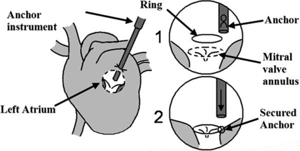
Mitral valve annuloplasty restores the function of defective mitral valves by reshaping the mitral annulus (the tissue perimeter around the valve) using a stiff ring. This ring can either be sutured or secured with metal anchors, the latter having been shown to produce promising results in atrial septal defect repair [8] (Fig. 1). The surgical instruments for anchor deployment are thin rigid tubes that are inserted into the left atrium through a purse-string suture on the exterior heart wall. The end of the instrument is then pressed against the annulus with a force of approximately 1.5 N to deploy an anchor to secure the ring, but less than about 4 N to avoid injuring delicate tissue. This proves to be difficult to accomplish manually due to the movement of the annulus with the beating of the heart. Therefore, the procedure requires an accurate force sensor that is robust to intracardiac conditions.
Fig. 1.
Proposed beating heart mitral valve annuloplasty procedure.
This application imposes following design constraints.
Waterproof: A waterproof seal is required in order to keep blood from the pressurized heart chamber from entering the sensor. Success involving force sensing with rubber materials has been shown in the past [9], and is incorporated in the proposed force sensor design to address this issue.
Electrical passivity: Surgical instrumentation must be electrically passive to avoid disrupting normal electrical activity in the heart. Optical fibers present a promising solution by eliminating the need for electrical signals in the force sensor. Miniature optical force sensors have been developed recently [3]–[6] but they rely on metal flexures for force transduction.
Miniaturization and location: The sensor must be located at the instrument tip to avoid the effect of friction and ancillary forces from the incision and purse string suture. For use within the heart, size must be minimized. A further constraint is that anchors must pass through the force sensor. Due to the largely uniaxial motion of the mitral valve annulus [10], only a single axis of force sensing is required, which aids miniaturization.
Material constraints: Beating heart procedures use 3-D ultrasound for guiding instrumentation inside the beating heart [10], [11]. Metals tend to create artifacts in ultrasound images, so polymers are preferred for clear imaging.
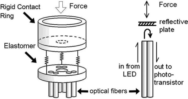
Fig. 2 presents the configuration and operating principle of the sensor. It uses three pairs of fiber optic cables, with each pair comprising a light-transmitting fiber and a light-receiving fiber, coupled to LED and phototransistor circuits, respectively [6]. A white plate 4 mm from the fibers reflects light from the emitting fiber to the receiving fiber, so the intensity of the light returned varies with the distance between the plate and fiber ends. Three pairs of optical fibers are placed in a triangle formation to minimize sensitivity to rotation of the reflective plate from off axis loads or uneven tissue contact. A solid elastomer element between the reflective plate and the optical fibers converts force to displacement, avoiding air gaps in the sensing element.
Fig. 2.
Left: configuration of sensor components. Right: force at the tip pushes the reflective plate closer, increasing the reflected light intensity.
B. Design
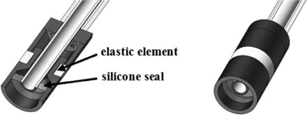
To ensure that the sensor is completely waterproof, the force sensor tip is sealed using a silicone seal between the sensor and the instrument shaft (Fig. 3). To minimize the effects of the seal during deformations of the elastic element, the silicone seal is cured as a thin film to reduce tension forces during axial deformation. The entire sensor surrounds a 2.1-mm hollow stainless steel tube through which instrumentation may pass.
Fig. 3.
Cross-section view.
C. Prototype
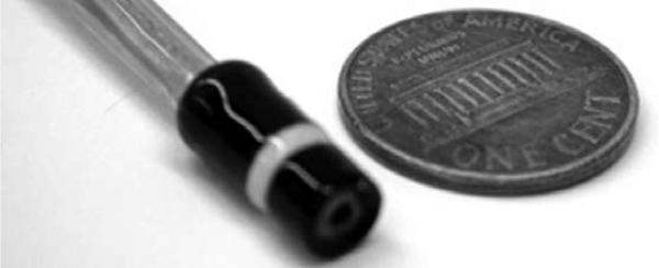
Fig. 4 shows the prototype device. The external diameter and length of the force sensor are 5.5 mm and 12 mm, respectively. Rigid components are made of acetal to lower interference in ultrasound images. The elastic component is a soft silicone rubber (Polysiloxane, Durometer 35), chosen for its low stiffness and low hysteresis. Deformation in the silicone rubber is limited to 500 μm under the maximum 4 N load.
Fig. 4.
Prototype sensor.
A plastic optical fiber with a 0.486/0.500-mm core/cladding diameter and a numerical aperture of 0.5 was used. LED and phototransistor modules (E3X-DA-N series, OMRON Industrial Automation, Schaumburg, IL, USA) measured the intensity of light. Voltage signals were filtered with a 1-kHz RC low-pass filter to reduce high-frequency noise.
III. Calibration
A nonlinear viscoelastic calibration for the force sensor is required, since the silicone rubber elastic element has nonlinear deflection characteristics and hysteresis. The time-independent response was empirically determined to be well characterized by a quadratic fit. To account for hysteresis of the silicone rubber dynamic response, a damping term was also included, resulting in the response equation
| (1) |
where F is the estimated force, Vfiber i is the voltage from the ith fiber, K1, K2 K3 are 1 × 3 gain matrices, and B is a constant bias. Since the fiber voltages are zeroed before each use of the force sensor, B is small. The derivatives dVfiber i /dt were calculated by differencing adjacent Vfiber i samples. Due to nonlinear terms, the K matrices vary between sensors of the same design, and individual calibration for each sensor is required.
To characterize the full range of the sensor, 0–4-N sinusoidal force chirps (up to 6 Hz) were applied to the fiber optic force sensor by a calibrated sensor (Mini40 force/torque sensor, ATI Industrial Automation, Apex, NC, USA). The calibration takes approximately 10 min and was performed in 37 °C water to duplicate in vivo conditions. Both sensors were sampled at 500 Hz. To attenuate high-frequency noise, a 250-Hz first-order low-pass Butterworth filter was applied to the voltage signals Vfiber_i and a 62.5-Hz first-order low-pass Butterworth filter was applied to the derivative terms.
The least squares estimates of the calibration are
| (2) |
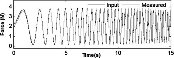
Fig. 5 shows the calibrated force plotted with the input force. The amplitude and phase of the signals match well, with a correlation coefficient (R2) of 0.9889, indicating good tracking from 0 to 6 Hz. Summary performance characteristics are as follows:
0.126-N rms error (<3.2% of force range);
0–4-N minimum force range;
0–6-Hz minimum frequency range.
Fig. 5.
Input force and sensor response for linear force chirp from 0 to 6 Hz.
To characterize the effect of radial (or shear) forces on the sensor, shear forces were applied. Steady state error was <0.3 N for up to 3 N of radial force. However, in annuloplasty, the shear forces are expected to be minimal since the annulus follows a nearly linear motion without significant lateral translation [10].
IV. Experimental Validation
A. In Vitro Triangle Wave Force Load Testing
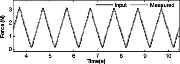
To confirm performance under a large dynamic range in amplitude and frequency, a triangle wave force input was applied. Fig. 6 shows the force input and sensor output with a 1-s period. The sensor accurately measured the signal with a 0.102-N rms error (< 3.2% of signal amplitude) and a correlation coefficient (R2) of 0.9867.
Fig. 6.
Triangle wave force trajectory (measured force versus applied force).
B. In Vivo Force Testing
In vivo tests were performed on healthy Yorkshire pigs, following an experimental protocol approved by the Institutional Animal Care and Use Committee. The force sensor was mounted on a 14-gauge needle and inserted into the beating heart through a purse-string suture in the left atrial appendage.
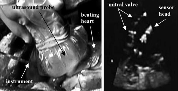
Visual feedback was provided to the surgeon by 3-D ultrasound (SONOS 7500, Philips Healthcare, Andover, MA, USA). Fig. 7 depicts the ultrasound appearance of the force sensor.
Fig. 7.
(Left) In vivo force sensing setup; Ultrasound probe is pressed against the beating porcine heart, and the force sensor is inserted in the left atrium. (Right) Ultrasound image of the mitral valve and force sensor inside the heart.
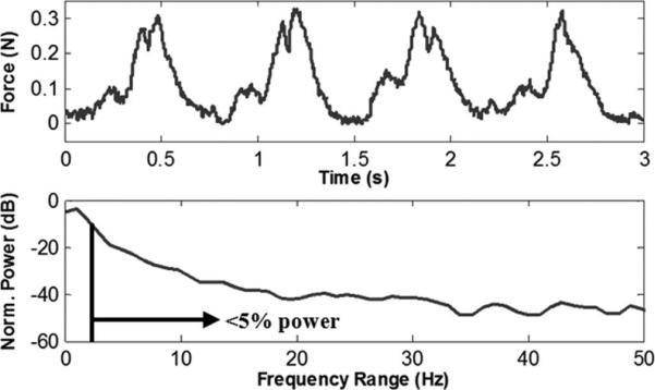
The instrument was held in contact with the mitral valve annulus to measure the forces of the instrument against the beating heart tissue (Fig. 8). The normalized power spectral density of the force signal showed that 95% of the power was below 2.9 Hz, with higher frequencies comprising only 5%, consistent with the design specification of a 6-Hz bandwidth.
Fig. 8.
Interaction forces between surgical instrument and mitral valve annulus during regular heartbeat, and power spectral density of the heartbeat forces.
C. In Vivo Tests in Beating Heart Anchor Deployment
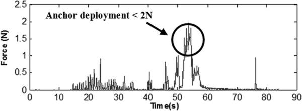
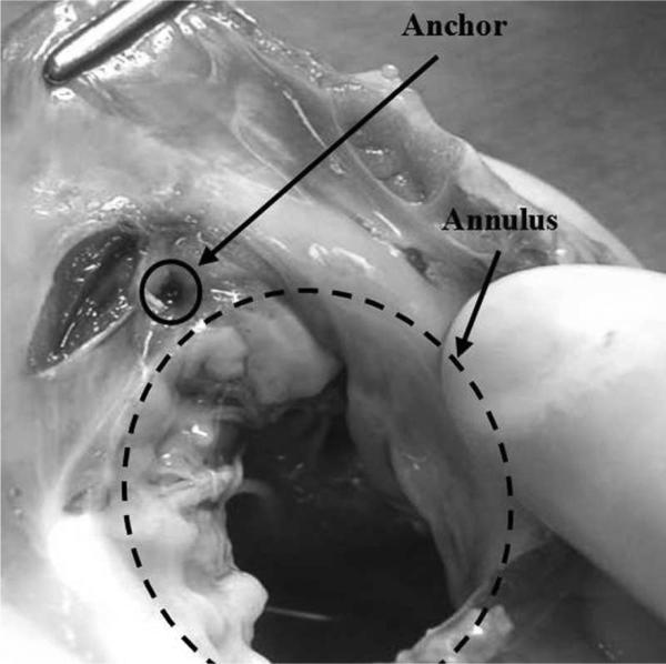
In a subsequent experiment, tests were performed on anchor deployment around the mitral annulus following our proposed beating heart mitral valve annuloplasty procedure. The force sensor was mounted on a 14-gauge needle containing deployable anchors and was inserted through the purse-string suture. The surgeon contacted the mitral valve annulus guided by 3-D ultrasound visual feedback and a real-time force display (a sliding bar indicating instantaneous force) from the fiber optic force sensor. The surgeon maintained a force near 1.5 N and deployed the anchors. Forces during anchor deployment did not exceed 2 N (Fig. 9). Post mortem examination showed that the anchor was successfully secured into the mitral valve annulus (Fig. 10).
Fig. 9.
Anchor deployment forces.
Fig. 10.
Excised annulus showing successful anchor deployment.
V. Discussion and Conclusion
In vitro and in vivo results indicate that the miniature sensor is capable of accurate force sensing inside the beating heart. In contrast with previous sensors [1]–[7], this design features an elastomer deflection element in place of metal flexures to create a waterproof unit. A viscoelastic calibration procedure provided good compensation for the inherent time-dependent and nonlinear response of the polymer material. To our knowledge, this is the first report of measurement of the interaction forces between an MIS instrument and internal heart structures during a beating heart procedure. Passive forces for a stationary instrument ranged from 0 to 0.3 N, while anchor deployment generated about 1.5 N forces; PSD analysis showed that 95% of power was at frequencies below 2.9 Hz. This suggests that a 0–4-N force range and 6-Hz bandwidth meets the requirements for task execution within the heart.
The integration of the sensor into a surgical instrument enabled successful anchor deployment into the moving annulus under 3-D ultrasound guidance. The surgeon found the force display intuitive and immediately relied on it during the procedure to control the applied force.
It should be noted that the sensor can only measure forces the surgeon applies along the axis of the instrument. In the current configuration, high shear forces will cause the inner components of the sensor to rub together and friction will affect the signal. However, in the target procedure, the essentially linear motion of the mitral valve annulus is likely to produce only minimal shear forces. The present design trades off multiaxis sensing capabilities in favor of simple and robust construction. The sensor can withstand loads over 10 N without damage, and dropping and inadvertent contacts during procedures do not cause damage. The use of polymer materials and straightforward construction may allow manufacturing using inexpensive molding techniques, which would make the sensor disposable after a single procedure.
The transmitted intensity can be sensitive to optical fiber bending. Losses become significant when bend radius falls below a few centimeters. During surgery, the fiber cables were kept fairly straight and rigid and fiber bending only contributed to roughly 3% in variations of the signal. Using single-mode multiclad optical fibers and stiffening the cabling can be implemented to further reduce bending effects.
Preliminary work suggests that it is possible to use the current optical fiber configuration to estimate the orientation of the reflective plate by comparing the relative output from each fiber. This would allow estimation of the direction of the applied force, thus creating a triaxial force sensor, which could be useful in other MIS applications. Development of a multiaxis sensor will require redesign of the internal sensor components to avoid friction and minimize sensor size while maintaining waterproof construction despite significant lateral deflections.
Another important consideration is the elastic element material properties. As with any force sensor, the elastic element (in this case silicone rubber) is subject to hysteresis and temperature effects. At frequencies above 6 Hz, the signal quality degrades. To better capture higher frequencies, the elastic element will need to be stiffer, lowering the resolution of the sensor. Thermal effects are minimal here due to the constant temperature environment within the beating heart.
This paper has demonstrated the viability of a miniature uniaxial optical force sensor for minimally invasive beating heart surgery. The sensor measures 5.5 mm in diameter, is made of ultrasound-friendly materials, and is completely waterproof and electrically passive; it also allows instrumentation to be passed through a central channel. In vitro characterization tests demonstrated a range of 0 to 4 N with less than 3% error and a bandwidth of 0–6 Hz. This sensor provided in vivo tissue force measurements in the interior of a beating heart. These measurements were displayed in real-time during surgery to permit the surgeon to determine the correct anchor deployment forces in beating heart mitral valve annuloplasty. Future work will involve exploring its potential uses in other forms of MIS, as well as expanding its sensing capabilities to measure triaxial forces.
Acknowledgment
The authors would like to thank N. Vasilyev, M.D., for his medical and technical assistance.
This work was supported in part by the U.S. National Institutes of Health under Grant NIH R01HL073647-01.
References
- 1.Valdastri P, Harada K, Menciassi A, Beccai L, Stefanini C, Fujie M, Dario P. Integration of a miniaturized triaxial force sensor in a minimally invasive surgical tool. IEEE Trans. Biomed. Eng. 2006 Nov.53(11):2397–2400. doi: 10.1109/TBME.2006.883618. [DOI] [PubMed] [Google Scholar]
- 2.Seibold U, Kuebler B, Hirzinger G. Prototype of instrument for minimally invasive surgery with 6-axis force sensing capability. Proc. IEEE Int. Conf. Robot. Autom. 2005:496–501. [Google Scholar]
- 3.Hirose S, Yoneda K. Development of optical 7-axial force sensor and its signal calibration considering non-linear interference. Proc. IEEE Int. Conf. Robot. Autom. 1990:46–53. [Google Scholar]
- 4.Puangmali P, Liu H, Althoefer K, Seneviratne LD. Optical fiber sensor for soft tissue investigation during minimally invasive surgery. Proc. IEEE Int. Conf. Robot. Autom. 2008:2934–2939. [Google Scholar]
- 5.Clijnen J, Reynaerts D, Van Brussel H. Development of a miniature optical tri-axial force sensor. Proc. SPIE Int. Soc. Opt. Eng. 2002;4946:129–136. [Google Scholar]
- 6.Peirs J, Clijnen J, Reynaerts D, Van Brussel H, Herijgers P, Corteville B, Boone S. A micro optical force sensor for force feedback during minimally invasive robotic surgery. Sens. Actuators A. 2004;115:447–445. [Google Scholar]
- 7.Berkelman PJ, Whitcomb LL, Taylor RH, Jensen PA. A miniature microsurgical instrument tip force sensor for enhanced force feedback during robot-assisted manipulation. IEEE Trans. Robot. Autom. 2003 Oct.19(5):917–921. [Google Scholar]
- 8.Reade CC, Bower CE, Bailey BM, Maziarz DM, Masroor S, Kypson AP, Nifong LW, Chitwood WR. Robotic mitral valve annuloplasty with double-arm nitinol U-Clips. Ann. Thoracic Surg. 2005;79(4):1372–1377. doi: 10.1016/j.athoracsur.2004.02.072. [DOI] [PubMed] [Google Scholar]
- 9.Ohka M, Mitsuya Y, Higashioka I, Kabeshita H. An experimental optical three-axis tactile sensor for micro-robots. Robotica. 2005;23:457–465. [Google Scholar]
- 10.Yuen SG, Kettler DT, Novotny PM, Plowes RD, Howe RD. Robotic motion compensation for beating heart intracardiac surgery. Int. J. Robot. Res. 2009;28:1355–1372. doi: 10.1177/0278364909104065. [DOI] [PMC free article] [PubMed] [Google Scholar]
- 11.Novotny PM, Stoll JA, Vasilyev NV, del Nido PJ, Dupont PE, Zickler TE, Howe RD. GPU based real-time instrument tracking with three-dimensional ultrasound. Med. Image Anal. 2007;11:458–464. doi: 10.1016/j.media.2007.06.009. [DOI] [PMC free article] [PubMed] [Google Scholar]


