

Abstract
The periodontal ligament (PDL) is a highly vascularized soft connective tissue. Previous studies suggest that the viscous component of the mechanical response may be explained by the deformation-induced collapse and expansion of internal voids (i.e. chiefly blood vessels) interacting with liquids (i.e. blood and interstitial fluids) flowing through the pores. In the present work we propose a methodology by means of which the morphology of the PDL vascular plexus can be monitored at different levels of compressive and tensile strains. To this end, 4-mm-diameter cylindrical specimens, comprising layers of bone, PDL and dentin covered by cementum, were strained at stretch ratios ranging from λ = 0.6 to λ = 1.4 and scanned using synchrotron radiation-based computer tomography. It was concluded that: (1) the PDL vascular network is layered in two distinct planes of blood vessels (BVs): an inner layer (close to the tooth), in which the BVs run in apico-coronal direction, and an outer layer (close to the alveolar bone), in which the BVs distribution is more diffuse; (2) during tension and compression, the porosity tissue is kept fairly constant; (3) mechanical straining induces important changes in BV diameters, possibly modifying the permeability of the PDL and thus contributing to the viscous component of the viscoelastic response observed under compressive forces.
Keywords: three-dimensional vascular network, morphology, periodontal ligament, synchrotron radiation-based tomography
Introduction
The present study is part of a research line addressing the mechanical response of the periodontal ligament (PDL). This specialized connective tissue interfaces the roots of the teeth with the supporting bone of the jaw (Ramfjord & Ash, 1979). Its primary function is to stabilize the teeth in their sockets and to serve as shock absorber during mastication. On a more subtle level, the PDL generates the eruptive forces of the teeth, provides afferent input during function (Beertsen et al. 1997) and reacts to external loads by augmenting tooth mobility or by causing the teeth to drift within the supporting bone (Hohlt & Roberts, 1994).
The tissue structure is complex and comprises both a solid and a liquid compartment sandwiched between two hard surfaces (tooth and bone). Compared to other ligaments, the PDL is highly vascularized – the blood vessels (BV) occupying 4–47% of the tissue volume (Blaushild et al. 1992; Sims et al. 1996). Biomechanically this translates into a conceptual framework consisting of a biphasic medium made of a porous matrix (fibers and ground substance) and a fluid filling the pores, that is, the blood vessels and interstitial voids (Bergomi et al. 2009b, 2010). In a few studies, this tissue was indeed visualized and modeled as a mixture of solid and fluid phases (van Driel et al. 2000; Natali et al. 2002).
Formerly published models of the mechanical behavior of soft tissues within poroelastic frameworks, such as intervertebral disks (Argoubi & Shirazi-Adl, 1996; Williams et al. 2007) or cartilage (Mansour & Mow, 1976; Mow et al. 1980), suggested that the tissue permeability was a function of the applied strain – a contention which might be justified when considering the collapse of the porous network upon mechanical loading.
Most studies on the three-dimensional morphology of the PDL vascular network were based on the corrosion cast technique using equine (Staszyk & Gasse, 2005; Masset et al. 2006a,b;), rat (Tsukada et al. 2000) or canine (Matsuo & Takahashi, 2002) tissue samples. The plexus was first ‘frozen’ by injecting self-polymerizing resin into the BVs. Then the soft tissue compartment was digested, leaving the vascular network down to single capillaries clearly visible. This technique provided high quality scanning electron microscopy images but, evidently, did not allow a monitoring of the BV network under functional loading.
The objective of the present study, therefore, was to investigate the micro-structural changes of the PDL under mechanical loading. More specifically, the aim was to develop an experimental methodology aimed at assessing the changes in BV volume and morphology during externally applied load.
Materials and methods
Principle of experiment
Five PDL samples (hereafter referred to as ‘S1 to S5’) were scanned with high-resolution synchrotron radiation-based tomography. Projection images were obtained by X-ray absorption techniques. To investigate the changes in PDL morphology during deformation, each sample was imaged at nine different states of strain [one control (no strain), four states of increasing compression and four of increasing tension]. The reconstructed images were then segmented to assess the respective volumes of the different tissue components.
Specimen preparation
Cylindrical specimens were extracted from bovine mandibular first molars. To this effect, previously described procedures were followed (Bergomi et al. 2009a). Briefly, blocks including first molar teeth and their surrounding bone were isolated from the mandibles of 3–6-year-old, freshly slaughtered bovines. The clinical crowns were sectioned and the orientation of the roots inside the bone was determined by inserting 0.5 mm steel wires into the pulp canals. Then a 4 mm (inner diameter) diamond-coated trephine drill aimed at the wires was used to extract cylindrical samples comprising layers of bone, PDL and dentin covered by cementum. For each block, specimens were obtained from 12 possible locations (distal ‘d’, mesial ‘m’, lingual ‘l’ or buccal ‘b’ aspect of the distal ‘d’ or mesial ‘m’ root, and at the coronal ‘I’ or apical ‘II’ vertical levels). Only samples whose PDL layer was oriented perpendicular to the long axis of the cylinder were deemed acceptable and stored in hermetic vials at −21 °C. All cutting procedures were conducted under profuse irrigation with saline (9 g L−1 NaCl). During transfer to the tomographic microscope facilities, the vials were placed in a container refrigerated to −5 °C. Several specimens were analyzed with the device. Due to a variety of causes (gripping failure, X-ray beam instability, faulty stretching), only five specimens were usable for analysis.
The specifics of each sample, that is, its origin (animal A, animal B), side of the jaw (left, right), the mesiodistal and buccolingual location and the level (coronal, apical) of the extraction site are listed in Table 1 and indicated in the diagram illustrating a transverse section of the mesial and distal roots of the bovine first molar.
Table 1.
Locations of extraction sites for the five specimens. Animal (A or B), side of the jaw (left L or right R), location around the tooth (distal d, mesial m, lingual l or buccal b aspect of the distal d or mesial m root) and depth level (coronal I or apical II). The locations are also indicated in the diagram.
 |
On the day of testing, the specimens were thawed to room temperature and their mineralized ends (cementum–dentin and bone) were secured to stainless steel holders (Fig. 1) with dental composite cement (Panavia F2.0, Kuraray, Japan). When the cement was fully polymerized (after 3 min), the specimens were mounted in a custom-made tensile-compressive testing device and placed on the rotary table of the tomographic microscope. The PDL tissue was kept moist at all times using an eyedropper and saline.
Fig. 1.

Bonding of the specimen onto the upper and lower holders.
Testing device
Three-dimensional images of PDL tissue at different strain levels were generated using the beamline for tomographic microscopy and coherent radiology experiments (TOMCAT) at the Swiss Light Source (SLS), Paul Scherrer Institut, Villigen, Switzerland (Stampanoni et al. 2007). To strain the samples while loaded in the TOMCAT, a micro-compressive device (MCD) for dynamic image-guided failure assessment (DIGFA), originally built at the Institute for Biomechanics, ETH Zürich, Zürich, Switzerland (Meier et al. 2008), was adapted for PDL samples. The MCD was initially designed for compression tests on hard tissues and was modified for the present study to allow both tensile and compressive tests on soft tissue samples. To this end, dedicated specimen holders were designed (parts 2 and 4 in Fig. 2A) and a new gripping mechanism was fabricated (part 1 in Fig. 2A). Both were included in the MCD. After the samples were adhesively fastened to the holders on the bonding jig (Fig. 1), the inner carbon fiber (CF) reinforced plastic tube (part 3 in Fig. 2A) was fitted over the specimen-holder assemblage. This CF plastic tube functioned both as an in situ glide bearing and as a container for the isotonic salt solution so that the moisture of the sample was maintained during the experiment. The clip (part 1 in Fig. 2A) was screw-fastened to the bottom of the load cell, which was mounted in series with the displacement-controlled motor of the MCD. The base-specimen assembly (parts 2 to 5 in Fig. 2A) was affixed to the rotary table of the TOMCAT. The combined motor assembly, load cell and clip were aligned on the specimen holder via the outer CF plastic tube (Fig. 2A). Coupling was obtained by lowering the clip onto the upper holder. The clipping procedure required a compressive force of about 18 N and was controlled by observing the real-time X-ray images of the clip and holder assemblage and by monitoring the output readings of the load cell.
Fig. 2.

Design (A) and 3D view (B) of the new tension-compression system fitted into the micro-compressive device (MCD) for dynamic image-guided failure assessments (DIGFA) (Meier et al. 2008). The clip is connected to the load cell of the MCD. Coupling is achieved by a controlled thrust of the clip onto the upper holder.
Mechanical loading
Zero state
The clipping procedure caused some compression of the PDL tissue. Therefore, prior to starting the experiment, the original (i.e. the zero state), non-compressed configuration of the specimen had to be re-established. For this purpose, a technique described by Sanctuary et al. (2005) was applied. It consisted in loading the samples in tension and in compression until a force of +10 N, respectively −10 N, was registered on the load cell. The ‘zero state’ was set as the midpoint between the displacements at +10 N and at −10 N. Then, the mean width  of the PDL space as assessed from X-ray projections (Fig. 3) was averaged from five equally distributed measurements of the gap separating the bone and the tooth surfaces.
Fig. 3.

The average width  of the PDL space was assessed from X-ray image projections.
  was averaged from five equally distributed measurements (indicated by dotted lines) of the gap separating the bone and the tooth surfaces.
Load profile
After the zero position was established, the specimens were preconditioned for 40 cycles with tensile-compressive displacement ramps at an amplitude of 0.25· and at a frequency of 1.0 Hz. Preconditioning expelled the air bubbles and debris included during extraction of the specimens (Bergomi et al. 2009b) (for a video recording of the preconditioning process, view http://lmaf.epfl.ch/attributs/Video/VideoPDL.wmv).
The stretch ratio  was defined as
  , where d(t) was taken as the displacement imposed by the MCD.
  was incremented from
  to
to  , in steps of 0.1.
Synchrotron radiation-based computed tomography
The TOMCAT synchrotron radiation-based computed tomography scans (SRCT) were obtained at 20 keV and a nominal resolution of 3.7 μm. The samples were first compressed to  , and then rotated over 180° in steps of 0.18°. Images were recorded with an exposure time of 140 ms at each of the 1001 individual steps. After measurement, the stretch ratio was automatically incremented to the next level (i.e.
  ). Before a new series of images was taken, the samples were allowed to relax for 4 min. The automatic procedure was repeated until
  reached 1.4. The entire process, including all stretching steps, image acquisition and relaxation, lasted 1 h and 20 min per specimen. Considering thawing (20 min), cementing (10 min) and mounting into the testing machine (5 min), each specimen was tested within 2 h. Reconstructed images (Fig. 4; 2048 × 2048 pixels) were obtained by applying standard filtered backprojection to the projection images (Fig. 3; 2048 × 813 pixels), so that 813 slices were obtained per sample and stretch ratio level.
Fig. 4.

Typical reconstructed slice of PDL tissue. Portions of dentin (light gray), BV (dark gray) and PDL matrix (gray) are visible. The image was obtained using SR CT at 20 keV and at a nominal resolution of 3.7 μm.
Data analysis
The variability in size (diameter) and density (BV surface per PDL unit area) of PDL blood vessels is quite high and depends on the animal and the site of specimen extraction (Bosshardt et al. 2008). As a consequence, any differences expressed in terms of mean BV volumes as computed by averaging the data obtained from several specimens tested at different levels of straining would be blurred by large standard deviations. Therefore, rather than inter-specimen comparisons, the present study was conducted using intra-specimen analyses (Bergomi et al. 2009b). Each specimen was subjected to the range of stretch ratios and the morphology of the vascular network was determined at each state of deformation. This information was then compared with the structural arrangements obtained at other stretch ratios within the same specimen. Pertinent data could thus be generated from a comparatively small population of samples.
Segmentation
The reconstructed images (Fig. 4) were segmented using the open source software itk-snap (http://www.itksnap.org), which was customized for semi-automatic analysis. Image post-processing consisted in selecting a volume of interest (VOI), that is, a box containing bone, PDL and tooth, and in a downscaling of 20% (i.e. resulting in a voxel size of 18.5 × 18.5 × 3.7 μm = 1266.3 μm3). A curvature diffusion filter (number of iterations = 5, time step = 0.0625, conductance = 3) was then applied to the VOI. Due to the fuzziness of the borderline separating the external milieu (i.e. the saline solution) from the PDL tissue (essentially due to reconstruction artifacts), the largest cylinder that was fully inscribed within the boundaries of the hard tissues was selected for analysis. The final segmentation was generated using threshold region growing, hand painting and hole filling techniques. Gray level ranges corresponding to the different structures (i.e. bone, tooth, BV and PDL matrix) were determined on the reconstructed images (Fig. 4). As the segmentation tools (i.e. thresholding and hand painting) were operator-dependent, it was of importance to evaluate the method error. To determine the variability introduced by the process, the procedure was performed four times on one single state of deformation for all five samples.
Quantitative morphology
For each strain level, porosity was computed as the vascular volume divided by the total volume of the PDL (i.e. BV plus matrix). To determine the lengths and diameters of the BVs, 3D meshes were exported in stl format. Measurements were conducted using an open source stl viewer (MiniMagics, http://www.materialise.com). The length of a blood vessel was taken as the sum of the linear segments of its axis. Spacing was taken as the average distance separating the axis of one BV from the axis of the nearby vessels. Branching was taken as any separations of a BV in two ‘subvessels’. The angles of the branches were also measured. Having determined the total length and the total volume of the PDL tissue, the mean linear density (total BV length/volume of PDL) and the mean diameter of the vessels could be computed. Connectivity was defined as the mean distance between branchings. It was calculated by dividing the total length of the BV by the number of branchings. The BV diameters were also measured on the 3D images.
Results
Mean values and standard deviations of the gray level intensities used to identify each tissue (i.e. bone, tooth, blood vessels and PDL matrix) are reported in Fig. 5A for each specimen (S1 to S5). Figure 5B shows a typical three-dimensional image obtained after segmentation.
Fig. 5.

Gray levels (A) of the different tissues of the five specimens. 3D visualization (B) of sample S2: green, bone; red, tooth; blue, bv; cyan, matrix (not shown in B).
The top layer of Fig. 5B is the alveolar bone (green), the dense layer at the bottom (red) is the cementum–dentin and the intermediary mesh in blue is the vascular network. Table 2 lists the means and standard deviations (SD) of the number of voxels obtained during the segmentation procedure of the BV network. The percent variability (i.e. SD/mean*100) introduced by the operator does not exceed 5.4% (for sample S5, which also presented the most complex vascular pattern, see Table 2 and Fig. 6I,J).
Table 2.
Variability of the segmentation process due to the use of operator-dependent tools.
| Specimen | BV (voxels) mean ± SD | Variability (%SD) |
|---|---|---|
| S1 | 5679 ± 48 | 0.84 |
| S2 | 7559 ± 202 | 2.68 |
| S3 | 10608 ± 187 | 1.76 |
| S4 | 900 ± 6 | 0.66 |
| S5 | 5416 ± 293 | 5.40 |
Fig. 6.

Bone-side (A,C,E,G,I) and tooth-side (B,D,F,H,J) views of the vascular network of specimens S1–S5. Whereas no general configuration could be evidenced for the outer layer (bone-side, in light green), the inner layer (tooth-side, in orange) presented a well-oriented BV network.
Descriptive morphology
Tooth and bone structures
Dentin and cementum (red) were dense, with occasional soft tissue inclusions. Their boundary with the PDL was quite smooth. The alveolar bone (green) was porous, often showing perforations through which blood vessels entered the PDL. The PDL-bone boundary was ragged, indicating a high level of bone remodeling.
Vascular plexus of the PDL
When viewed in three dimensions, the vascular network comprised two distinct layers of blood vessels. To assist in differentiating the layers, the uniform blue color used in Fig. 5B was turned into light green or orange (Fig. 6):
The outer layer (close to the bone side – light green) was mostly unstructured. The three-dimensional arrangement of the vessels presented no preferential orientation. The BV diameters were highly variable, ranging from capillary-sized to large, reservoir-like structures.
The inner layer (close to the tooth – orange) was arranged in a well-structured pattern, with regularly spaced, unidirectionally oriented BVs. These BVs were typically arranged in planes. When compared to the outer layer BVs, their diameters were small to medium in size.
The two layers were linked by small to medium-sized blood vessels. These connections were roughly perpendicular to the tooth surface. Figure 6 shows the bone-side view (A,C,E,G,I) and the tooth-side view (B,D,F,H,J) of the vascular network of all five specimens in the unstrained state. This pattern was observed in four of the five samples (the inner network of sample S5 was less structured than samples S1–S4).
Quantitative morphology
BV volume and porosity as a function of stretch ratio
Figure 7 shows a 2D segmented transverse section of specimen S2 at stretch ratio levels  (Fig. 7A),
  (Fig. 7B) and
  (Fig. 7C), respectively. The arrow indicates the same location of a BV in the three strained states. The evolution of the vascular volume (in voxels, 1vx = 1266.3 μm3) of the five samples is shown in Fig. 8A. Changes were more pronounced between the unstrained (
 ) and the compressed (
 ) condition relative to those observed between the unstrained and the taut (
 ) state. The evolution of porosity is reported in Fig. 8B. The inter-specimen differences were high (the specimens presented initial porosities of 15–32% (Fig. 8B, dotted line). However, within single specimens the porosity appeared as relatively constant over the selected strain range.
Fig. 7.

Segmented transversal sections of specimen S2 in the compressed (A,  ), the unstrained (B,
  ) and the taut (C,
  ) states. The arrow points at the same BV in the three configurations.
Fig. 8.
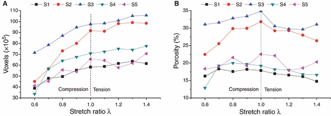
Evolution of BV volume (A) and porosity (B) as a function of stretch ratio for the five samples.
Morphometric parameters of the PDL vascular plexus
The pattern of the inner vascular layer was well structured. It was thus possible to calculate the lengths and spacings between vessels, as well as the number and angles of their branchings. The morphology of the outer vascular layer (i.e. close to the bone) only just lent itself to the direct measurements of lengths, spacings, number of connections or angles. Still, an estimate of BV diameters could be obtained from the 3D images. Linear densities were calculated by dividing the volume of the BV outer network by the mean cross-sectional area of the vessels. The values of these parameters for the two vascular layers are shown in Table 3. Figure 9 depicts the frequency distributions of BV diameters of the outer and inner plexus as measured on the 3D meshes. The mean values listed in Table 3 are shown by dotted lines.
Table 3.
Morphometric description of the two-layered BV plexus. Spacing, connectivity and angle were not defined for the outer layer.
| Layer | Linear density (mm mm−3) | Diameter (μm) | Spacing (μm) | Connectivity (mm per number) | Angle (°) |
|---|---|---|---|---|---|
| Inner | 9.6 ± 2.7 | 60 ± 11 | 248 ± 27 | 1.90 ± 0.24 | 35.8 ± 9.3 |
| Outer | 12 ± 5.9 | 126 ± 35 | – | – | – |
Fig. 9.

Frequency distributions for the outer (A) and inner (B) BV network. Dotted line: arithmetic mean.
Discussion
Previous work on bovine PDL demonstrated marked inter-specimen differences in both morphological and mechanical characteristics (Shibata et al. 2006; Bergomi et al. 2009b). Indeed, the PDL widths, the orientation of collagen fibers within the tissue, the bone-PDL-tooth boundary profiles, the sizes, positions and densities of the blood vessels notably varied between specimens (Bosshardt et al. 2008), thus precluding the depiction of an all-encompassing morphological pattern for this tissue. This biovariability is essentially caused by the ongoing remodeling of the bony structures and the rapid turnover of the soft tissue (van den Bos & Tonino, 1984). These phenomena also induce important disparities in the mechanical behavior of the specimens (Bergomi et al. 2009a) and hamper a standard normative interpretation of the data. Consequently, it was of importance to establish a protocol that permitted an observation of the changes in PDL microstructure for each sample and each level of straining. Clearly, classical histological sections and corrosion cast techniques were not suitable for this purpose. Magnetic resonance imaging (MRI) and computed tomography (CT) are both suitable for a non-destructive volumetric reconstruction of bulk specimens and were considered initially. Preliminary investigations, however, indicated that interpretable information could not be obtained from MRI techniques. Indeed, views generated using a 14.1 Tesla scanner (Centre d’Imagerie BioMédicale, CIBM, EPFL, Lausanne, Switzerland) could not adequately discriminate between the structural components of the soft tissue. Also, the maximal resolution of the images (40 μm) was insufficient. Synchrotron radiation-based tomography, which allows for high-resolution, high-contrast and fast data acquisition, thus appeared to be a proper alternative.
Experimental setup
The modified design of the gripping system of the MCD allowed both tensile and compressive loading of soft tissue specimens while mounted in the tomographic scanner. During clipping of the samples to the device, a compressive load of approximately 18 N was applied to the 4 mm diameter specimen, resulting in a stress of approximately 1.4 MPa. Previous studies (Bergomi et al. 2009a) established that similar compressive stress levels did not induce notable changes in the mechanical response of the specimens.
The setting of the zero origin via the integrated load cell was essential whenever correspondence to previously recorded mechanical data were to be established.
Collagen fibers and BV walls were at risk of damage during freezing due to the formation of ice crystals. Crystal formation can be prevented by adding propylene- and ethylene glycol to the medium. This option might be considered in future tests.
Owing to the high data throughput provided by the TOMCAT beamline, scanning time was kept within an acceptable duration (< 2 h including thawing and cementing of the specimens). Also, the specimens were immersed in saline solution throughout the testing procedure, thus ensuring that no or only minor tissue degradation occurred during the imaging process.
Segmentation
Gray level values for bone and tooth were fairly close to each other. Nonetheless, semi-automatic segmentation based on threshold region growing techniques was feasible because of the physical distance separating both structures. Discriminating between BVs and PDL matrix was more intricate. These two tissues were in contact with each other and their range of gray levels at times overlapped. This was mainly due to artifacts introduced by the algorithm that calculated the reconstructed images. The phenomenon prevailed in the vicinity of the densely mineralized structures as a slight gray level gradient affecting the pixel intensity of the adjacent soft tissues. In these zones, threshold region growing segmentation was not reliably applicable and manual masking and painting were used to improve the segmentation of the BVs and PDL matrix, respectively. However, the error thus induced by the operator was small.
Tooth and bone features
In line with previously reported data (Bosshardt et al. 2008), the bovine dentin was densely packed and occasional soft tissue channels and/or BVs could be found in the cementum layer. This latter characteristic is species-specific and is not observed in humans. The tooth interface with the PDL was fairly even, whereas the osseous wall presented numerous perforations (Matsuo & Takahashi, 2002) through which BVs connected to the PDL space. Numerous resorption lacunae also housed BVs. The bone surface was jagged and tortuous – a morphology indicative of intense remodeling processes similar to that observed previously (Bosshardt et al. 2008).
BV plexus features
Two-layered structures of vascular plexuses have been described in horses (Staszyk & Gasse, 2005; Masset et al. 2006a,b;) and dogs (Matsuo & Takahashi, 2002). A general orientation of the BVs in the occluso-apical direction was also demonstrated (Tsukada et al. 2000; Matsuo & Takahashi, 2002; Masset et al 2006a). As shown in Fig. 6, a similar orientation clearly appeared in the inner BV layer of bovine PDL only. At the specimen dimensional scale, less information can be provided regarding the outer BV layer. Indeed, at variance with corrosion cast techniques, the technique applied herein did not permit an observation of the BV plexus along the entire root length. Still, an occluso-apical course was observed for the outer layer of BVs in dog molars (Matsuo & Takahashi, 2002) and horse premolars and molars (Masset et al. 2006a). A similar orientation may thus be expected in the case of bovine molars as well.
Blood pressure was not considered during testing. Our results may thus slightly underestimate the actual BV diameters and volume. Preconditioning (i.e. pumping water in and out of the vessels) as well as relaxation (i.e. when the elastic properties of the tissue dominate the final response) in saline before proceeding with the measurements, should have minimized this difference.
Within each specimen and for all levels of straining, porosity was relatively constant. This stability might be attributed to the high compressibility of the collagen matrix (Bergomi et al. 2009b). The disparities in porosity between samples are attributed to natural biovariability and the various rates of tissue turnover that develop on different teeth.
Mean diameters and linear densities were larger for the BVs of the outer layer than for those of the inner layer. As suggested by Masset et al. (2006a), the wide BVs of the outer layer might act as shock absorbers, and the capillaries of the inner layer supply nutriments to the tissue. During mechanical loading, however, it was noticed that the vessels of both layers undergo dimensional changes, thus suggesting that the inner layer may also contribute to the process of mechanical damping. Due to the small number of specimens analyzed, possible correlations between morphological patterns and sites of specimen extraction along the roots lacked significance and were therefore not pursued. In light of the important biovariability shown in the present and in other studies (Bosshardt et al. 2008), meaningful correlations could hardly be expected.
Implications for mechanical behavior
Previous studies on the mechanical behavior of soft tissues, e.g. intervertebral disks (Argoubi & Shirazi-Adl, 1996; Silva et al. 2005; Williams et al. 2007), suggested that the viscous component of their response is induced by modification of the tissue permeability resulting from pore collapse during mechanical loading. Indeed, the compression of a porous and collapsible structure would entail a progressive decrease of porosity and thus reduce permeability. To model this phenomenon, a poroelastic framework in which permeability depends on porosity via an exponential relationship was proposed (Argoubi & Shirazi-Adl, 1996). The present work provides experimental data regarding this relationship: it was found that porosity remained constant over the measured range of straining, thus suggesting that permeability is a function of the cross-sectional area of the BVs, rather than a function of porosity.
Previous studies have demonstrated that the PDL mechanical behavior was markedly different when activated in tension or in compression. Whereas the tensile response was hyperelastic, the PDL responded viscoelastically under compressive loading (Shibata et al. 2006; Bergomi et al. 2009b). The pores of the PDL (i.e. the BVs) are interconnected and communicate with their environment, i.e. with the surrounding alveolar bone (Bergomi et al. 2009b), thus permitting a to-and-fro movement of liquid during straining. The present results suggest that the magnitude of fluid flow is largely conditioned by the expansion and collapse of BVs whenever liquid is forced into or out of the tissue. It is thus conceivable that the decrease in tissue permeability during compression induces the viscosity of the observed behavior. In tension, the BVs expand and increase the permeability of the tissue, so that the coupling between the fluid and the solid phase is less pronounced.
Also, recent studies on the mechanical behavior of bovine PDL under sinusoidal straining demonstrated that the response of this soft tissue was best interpreted as a result of the interaction between a highly compressible, porous, hyperelastic matrix and a fluid phase that flows through the pores during stretching (fluid intake) and compression (fluid loss) (Bergomi et al. 2009b, 2010). The present study indicates that heterogeneity and anisotropy should definitely be considered when modeling the response of such a porous structure. The preferential orientation of the inner vascular layer, the level of porosity, and the variations in BV diameter upon straining are parameters to be included into a model that aims at encompassing both the tensile and the compressive responses of PDL tissue.
Conclusions
The blood vessel network of the PDL is organized in a two-layer structure. The inner layer (close to the tooth) presents an organized structure with small to medium-sized BVs oriented in apico-coronal direction. The outer layer (close to the alveolar bone) is less organized, with relatively large vessels.
Mechanical straining induces important modifications in the diameters of the blood vessels. It is suggested that these changes condition the permeability of the periodontal ligament and contribute significantly to its viscoelastic response under compressive forces.
Acknowledgments
Our gratitude is expressed to Mr. M. Lai (EPFL, LMAF), Mr. M. Hitz and Mrs A. Levchuk (Institute for Biomechanics, ETH Zürich), Dr. F. Marone (PSI, SLS) and Dr. V. Mlynarik (EPFL, CIBM) for their technical assistance. Dr. M. Bergomi wishes to thank Dr. C. Bernasconi (DEE, Université de Lausanne, Switzerland) for having introduced him to synchrotron radiation-based computed tomographic techniques. The authors gratefully acknowledge the financial support from the Swiss National Science Foundation under grants 3152-055863.98 and 21-64562.01.
References
- Argoubi M, Shirazi-Adl A. Poroelastic creep response analysis of a lumbar motion segment in compression. J Biomech. 1996;29:1331–1339. doi: 10.1016/0021-9290(96)00035-8. [DOI] [PubMed] [Google Scholar]
- Beertsen W, McCulloch CAG, Sodek J. The periodontal ligament: A unique, multifunctional connective tissue. Periodontol 2000. 1997;13:20–40. doi: 10.1111/j.1600-0757.1997.tb00094.x. [DOI] [PubMed] [Google Scholar]
- Bergomi M, Wiskott AHW, Botsis J, et al. Mechanical response of periodontal ligament: Effects of specimen geometry, preconditioning cycles and time lapse. J Biomech. 2009a;42:2410–2414. doi: 10.1016/j.jbiomech.2009.06.031. [DOI] [PubMed] [Google Scholar]
- Bergomi M, Wiskott HWA, Botsis J, et al. Load-response of periodontal ligament: assessment of fluid flow, compressibility and effect of pore pressure. J Biomech Eng. 2009b;132:014504. doi: 10.1115/1.4000154. 5pp. [DOI] [PubMed] [Google Scholar]
- Bergomi M, Cugnoni J, Wiskott HWA, et al. The role of the fluid phase in the viscous response of bovine periodontal ligament. J Biomech. 2010;43:1146–1152. doi: 10.1016/j.jbiomech.2009.12.020. [DOI] [PubMed] [Google Scholar]
- Blaushild N, Michaeli Y, Steigman S. Histomorphometric study of the periodontal vasculature of the rat incisor. J Dent Res. 1992;71:1908–1912. doi: 10.1177/00220345920710121001. [DOI] [PubMed] [Google Scholar]
- van den Bos T, Tonino GJ. Composition and metabolism of the extracellular matrix in the periodontal ligament of impeded and unimpeded rat incisors. Arch Oral Biol. 1984;29:893–897. doi: 10.1016/0003-9969(84)90088-8. [DOI] [PubMed] [Google Scholar]
- Bosshardt DD, Bergomi M, Vaglio G, et al. Regional structural characteristics of bovine periodontal ligament samples and their suitability for biomechanical tests. J Anat. 2008;212:319–329. doi: 10.1111/j.1469-7580.2008.00856.x. [DOI] [PMC free article] [PubMed] [Google Scholar]
- van Driel WD, van Leeuwen EJ, Von den Hoff JW, et al. Time-dependent mechanical behaviour of the periodontal ligament. Proc Inst Mech Eng H. 2000;214:497–504. doi: 10.1243/0954411001535525. [DOI] [PubMed] [Google Scholar]
- Hohlt VVE, Roberts WE. Rigid implants for orthodontic anchorage. In: Davidovitch Z, editor. Biological Mechanisms of Tooth Eruption, Resorption and Replacement by Implants. Birmingham: EBSCO Media; 1994. pp. 661–666. [Google Scholar]
- Mansour JM, Mow VC. Permeability of articular cartilage under compressive strain and at high pressures. J Bone Joint Surg Am. 1976;58:509–516. [PubMed] [Google Scholar]
- Masset A, Staszyk C, Gasse H. The blood vessel system in the periodontal ligament of the equine cheek teeth - Part I: The spatial arrangement in layers. Ann Anat. 2006a;188:529–533. doi: 10.1016/j.aanat.2006.06.010. [DOI] [PubMed] [Google Scholar]
- Masset A, Staszyk C, Gasse H. The blood vessel system in the periodontal ligament of the equine cheek teeth - Part II: The micro-architecture and its functional implications in a constantly remodelling system. Ann Anat. 2006b;188:535–539. doi: 10.1016/j.aanat.2006.06.007. [DOI] [PubMed] [Google Scholar]
- Matsuo M, Takahashi K. Scanning electron microscopic observation of microvasculature in periodontium. Microsc Res Tech. 2002;56:3–14. doi: 10.1002/jemt.10008. [DOI] [PubMed] [Google Scholar]
- Meier M, Vogel P, Voide R, et al. Investigation of microdamage in murine bone under dynamic load. J Biomech. 2008;41:S76. [Google Scholar]
- Mow VC, Kuei SC, Lai WM, et al. Biphasic creep and stress-relaxation of articular-cartilage in compression – Theory and experiments. J Biomech Eng. 1980;102:73–84. doi: 10.1115/1.3138202. [DOI] [PubMed] [Google Scholar]
- Natali AN, Pavan PG, Schrefler BA, et al. A multi-phase media formulation for biomechanical analysis of periodontal ligament. Meccanica. 2002;37:407–418. [Google Scholar]
- Ramfjord SP, Ash MM. Periodontology and Periodontics. St. Louis: W.B. Saunders Company; 1979. [Google Scholar]
- Sanctuary CS, Wiskott HWA, Justiz J, et al. In vitro time-dependent response of periodontal ligament to mechanical loading. J Appl Physiol. 2005;99:2369–2378. doi: 10.1152/japplphysiol.00486.2005. [DOI] [PubMed] [Google Scholar]
- Shibata T, Botsis J, Bergomi M, et al. Mechanical behavior of bovine periodontal ligament under tension-compression cyclic displacements. Eur J Oral Sci. 2006;114:74–82. doi: 10.1111/j.1600-0722.2006.00269.x. [DOI] [PubMed] [Google Scholar]
- Silva P, Crozier S, Veidt M, et al. An experimental and finite element poroelastic creep response analysis of an intervertebral hydrogel disc model in axial compression. J Mater Sci Mater Med. 2005;16:663–669. doi: 10.1007/s10856-005-2538-0. [DOI] [PubMed] [Google Scholar]
- Sims MR, Leppard PI, Sampson WJ, et al. Microvascular luminal volume changes in aged mouse periodontal ligament. J Dent Res. 1996;75:1503–1511. doi: 10.1177/00220345960750071101. [DOI] [PubMed] [Google Scholar]
- Stampanoni M, Groso A, Isenegger A, et al. TOMCAT: A beamline for TOmographic Microscopy and Coherent rAdiology experimenTs. Synchrotron Radiat Instrum. 2007;879:848–851. [Google Scholar]
- Staszyk C, Gasse H. Distinct fibro-vascular arrangements in the periodontal ligament of the horse. Arch Oral Biol. 2005;50:439–447. doi: 10.1016/j.archoralbio.2004.10.001. [DOI] [PubMed] [Google Scholar]
- Tsukada H, Ishikawa H, Nakamura S, et al. Developmental changes of the vasculature in the periodontal ligament of rat molars: A scanning electron microscopic study of microcorrosion casts. J Periodontal Res. 2000;35:201–207. doi: 10.1034/j.1600-0765.2000.035004201.x. [DOI] [PubMed] [Google Scholar]
- Williams JR, Natarajan RN, Andersson GBJ. Inclusion of regional poroelastic material properties better predicts biomechanical behavior of lumbar discs subjected to dynamic loading. J Biomech. 2007;40:1981–1987. doi: 10.1016/j.jbiomech.2006.09.022. [DOI] [PMC free article] [PubMed] [Google Scholar]