Abstract
Cell migration under chemoattractant is an important biological step in cancer metastasis that causes the spread of malignant tumor cells. Porous polymeric materials are widely used to mimic the extracellular matrix (ECM) environment for applications such as three dimensional (3D) cell culturing and tissue engineering. In this paper we report a novel 3D cell culture device based on porous polymeric material to study cancer migration. We fabricated a porous channel on a polymeric chip using a selective ultrasonic foaming method. We demonstrate that a chemical concentration gradient could be established through the porous channel due to the slow diffusion process. We show that significant cell migration could be observed through the porous channel within 1–2 weeks of cell culturing when metastatic M4A4-GFP breast cancer cells were induced by 20% fetal bovine serum (FBS). We also developed a mathematical model to evaluate the diffusivity and concentration gradient through the fabricated porous structure.
Keywords: Cell migration, Porous structure, Selective ultrasonic foaming, Diffusion in porous media
1 Introduction
Cells are stimulated to migrate in response to certain chemicals in many biological processes, including not only favorable physiological processes, such as leukocyte recruitment to inflammation sites and fibroblast and vascular endothelial cell movement in wound healing, but also in undesirable pathological progression of illness including cancer metastasis (Lauffenburger and Horwitz 1996). Cancer metastasis contributes the most to the spread of malignant tumor cells (Chambers et al. 2002; Ruoslahti 1996). In the cancer metastasis process, several tumor cells first acquire an invasive phenotype and detach from the surrounding stroma. They then intravasate into tumor blood vessels, going through the basement membrane, penetrating the vascular or lymphatic vessel linings, and moving along with the circulatory system. Finally they settle in a new place where secondary tumors are established by invading through the basement membrane and surrounding stroma of the new site.
To understand the complex process of cancer metastasis, many in vitro assays have been developed to study the underlying molecular mechanism and to discover factors that would promote or inhibit the cancer migration process. Traditionally, cancer migration and invasion assays have been conducted using Boyden chambers (Boyden 1962) and Transwell apparatus (Brackenbury and Djamgoz 2007; Ponath et al. 2000; Ruster et al. 2005) for qualitative and quantitative assessment of cellular response to soluble factors. The measurements involved in these assays are cumbersome and time-consuming, especially in the case of Transwell cell culture assays, where the cells both attached to the filter surface and dropped in the lower chamber need to be counted.
With the development of microfabrication techniques, many biochip devices were designed for convenient cell migration assays. Most of the migration substrates used in these assays, however, were simple 2D surfaces (Webb et al. 1996; Zicha et al. 1997). Migration on rigid and 2D planar substrates fails to reproduce cell behaviors in vivo (Decaestecker et al. 2007). Compared with 2D cellular migration, 3D assays could provide a more realistic microenvironment and better information on the in vivo cell migration behavior. Therefore, 3D cell migration studies are drawing more and more attention from both academia and industry (Even-Ram and Yamada 2005). Recently, a three-channel, hydrogel-based microfluidic device was developed to study the bacteria cell migration. Steady and long term linear chemical concentration gradient was established by flowing a chemoattractant in a source channel and a blank buffer in a sink channel (Chaw et al. 2006; Diao et al. 2006; Lee et al. 2008). Cells were cultured in the third channel filled with hydrogel. The device was successful in observing individual cell migration in the transverse direction of the microfluidic channel.
In this paper we report a novel porous polymer based 3D cell culture device for cancer migration studies. Porous polymeric material has been widely used to mimic the extracellular matrix in many biomedical applications including tissue engineering and controlled drug release (Al-Sokanee et al. 2009; Cho et al. 2005; Huang et al. 2007; Li et al. 2008; Lin et al. 2009; Uttarwar and Aswath 2008). It can provide a more realistic microenvironment to study in vivo cell behaviors. In this study, we employ high intensity focused ultrasound (HIFU) to create a 3D porous channel selectively on a polymeric chip. We show that a chemical concentration gradient can be established with the slow diffusion process in the porous channel. We demonstrate that significant cell migration can be induced by 20% fetal bovine serum (FBS) within 1–2 weeks of cell growth. A mathematical model was also developed to evaluate the diffusivity and concentration gradient through the fabricated porous structure.
2 Materials and methods
2.1 Fabrication of the 3D cell migration device
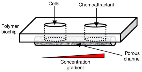
A schematic of the porous 3D cell migration device is shown in Fig. 1. The key element of the device was a porous channel used to observe the cell migration process under a concentration gradient. Two wells were fabricated on either side of the porous channel. The well on the left was used to seed with cancer cells, and the one on the right was filled with a chemoattractant. A chemical gradient was established through diffusion in the porous channel. The material of the biochip device can be any biocompatible thermoplastic materials. In this study, polymethylmethacrylate (PMMA) (Professional Plastics Inc, CA) was used.
Fig. 1.
A schematic of the porous cell migration chip design
The porous channel was fabricated using a selective ultrasonic foaming process with high intensity focused ultrasound (HIFU) (Wang and Li 2007, 2008). The selective foaming process involved two steps: gas saturation and HIFU insonation. In the gas saturation step, a polymer sample was loaded in a high pressure vessel filled with CO2. After a controlled saturation time, the polymer sample was retrieved from the pressure vessel. In the HIFU insonation step, the saturated sample was mounted on a computer controlled positioning stage for ultrasound insonation. Since it was supersaturated with CO2, the polymer sample was thermodynamically instable. Upon insonation, the sample underwent phase separation and formed porous structure when the gas molecules left the polymer matrix.
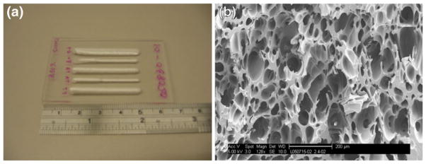
Figure 2 shows an example of the fabricated porous structure in a polymer chip. Figure 2(a) shows that many linear porous channels could be generated on a single PMMA chip. The length and width of the porous channels could be controlled with the ultrasonic foaming parameters. Figure 2(b) shows the typical internal porous structure of those foamed channels. The porous structure was interconnected with an average pore size around 100 μm.
Fig. 2.
HIFU foamed PMMA sample, (a) linear porous regions foamed on a PMMA chip, (b) a typical scanning electron microscopy image of the internal porous structure, scale bar is 200 um
We fabricated three types of biochip devices for the cell migration study. As shown in Fig. 3, Samples A and B were designed to study whether the cells would migrate under certain chemoattractant and whether the distance of the chemoattractant could affect the migration study. Two sets of wells were made in each sample, one used for test and the other for control. The distances between the two wells were 5 mm in Sample A and 1 mm in Sample B. All the wells could hold 50 μL fluid. In the experiment, the wells on the left were seeded with cancer cells. The ones on the right were filled with culture media with or without 20% FBS. 20% FBS was used to generate a concentration gradient of attractant molecules for inducing directional cell migration. The same concentration was also used by Chaw et al. (2007). Sample C was used to observe the cell migration in steps. Sample C was designed to have larger wells (100 μL) such that more cells could be seeded. The distance between the two wells in Sample C was 1 mm. Distilled water was used to confirm that the porous channels in all the samples were interconnected.
Fig. 3.

3D porous cell migration biochip samples: (a) Sample A, cells seeded in the left wells, 20% FBS and non-FBS culture medium in the right wells (wells 1 and 2), and 5 mm distance in between; (b) Sample B, cells seeded in the left wells, 20% FBS and Non FBS culture medium in the right wells (wells 3 and 4), 1 mm distance in between; (c) Sample C, cells seeded in the left well, 20% FBS in the left, 1 mm distance in between
2.2 Cell culture
All the migration biochip samples were rinsed with purified water several times, dried by centrifuging at 2,000 rpm for 5 min, and sterilized with ultraviolet light for 30 min. Sterilized samples were soaked in FBS-free Dulbecco’s modified eagle medium (DMEM) for 3 days before cell seeding. Highly metastatic breast cancers (cell line M4A4-GFP, purchased from ATCC) were cultured in a 10 cm Petri dish with DMEM containing 10% FBS at 37°C and 5% CO2. The cell line was developed by transduction of the green fluorescent protein (GFP) gene into M4A4. The cells emit strong green fluorescence at the excitation wavelength of 488 nm. Before seeding onto the samples, the cells were detached from the Petri dish with 0.25% Trypsin and centrifuged at 1,000 rpm for 5 min. The liquid at the top of the tube was discarded. Then 1 mL FBS-free medium was added to re-suspend the cells. All the cells used in this study were in their 3–6 passages.
Approximately 5×10³ cells in 50 μL FBS-free culture medium were seeded in the left wells of Samples A and B. After seeding the samples were incubated for 1 h to allow cell attachment to the porous scaffolds. Then 50 μL culture medium with 20% FBS was added to Wells 1 and 3 (Fig. 3), respectively, to induce cell migration from the left wells. Non FBS culture medium was added to Wells 2 and 4 as the control. All the samples were placed in a 6-well plate and incubated at 37°C and 5% CO2. The culture media in all the wells were replaced every 2–3 days to maintain the concentration gradient. Sample C was similarly seeded as Samples A and B, except the fluid volume in each well was maintained at 100 μL. The number of cells seeded in the left well of Sample C was 5×10⁴.
2.3 Imaging
A fluorescent stereomicroscope (Leica M205A) was used to detect if the cells have migrated in Samples A and B. Images were taken after 7 days of cell culture. Cell migration history in Sample C was examined using IsoCyte Laser Scanning Cytometer (Blueshift Biotechnologies) at 1, 2, 5, and 10 days. The laser scanning cytometer uses a laser source to excite fluorescence signal point-by-point and detect the emission signals with highly-sensitive photomultiplier tubes. By steering the laser beam to form a raster scan, fluorescent cells inside 3D porous structure could be imaged. In our study the cells were excited with a laser of 488 nm wavelength. The scanning was done on a layer that gave the best fluorescent signals. This layer was 0.6 mm above the bottom of the culture plate. After 14 days of cell culturing, Sample C was also examined using a confocal microscope (Zeiss LSM 510) to observe the cellular clusters. To confirm the cell attachment, Sample C was fixed with Karnovsky’s fixative, freeze-fractured, and the cross-section observed using a scanning electron microscope (FEI Sirion).
3 Results and discussion
3.1 Cell migration results
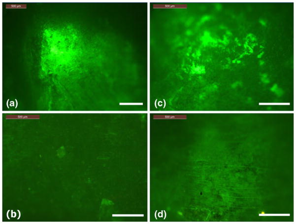
Figure 4 shows the fluorescence imaging results from Samples A and B after 7 days of cell culturing. Figures 4(a)–(d) correspond to Wells 1–4 in Fig. 3. These wells were originally not seeded with cells. After 7 days, strong fluorescence signals were observed in Wells 1 and 3, indicating cells had migrated to these two wells. However, no fluorescence signals were detected in Wells 2 and 4. The distance between the wells did not seem to affect the results.
Fig. 4.
Fluorescence images, (a) Well 1 in Sample A, (b) Well 2 in Sample A, (c) Well 3 in Sample B, and (d) Well 4 in Sample B. Note Wells 1 and 3 were filled with 50 uL 20% FBS, where Wells 2 and 4 were not. The scale bar in the figures is 500 μm
Most cancer cells will migrate both spontaneously and induced by certain chemicals (Niggemann et al. 2004). These two modes of migration are hard to distinguish at times. The observations from Fig. 4 confirmed that the cell migrations to Wells 1 and 3 in our study were indeed caused by the chemoattractant effect of FBS.
Figure 5 shows the Isocyte laser scanning results from Sample C at 1, 2, 5, and 10 days of cell culturing. The fluorescence signal is shown in red (dark) in the figures. It is seen that at Day 1 most of the cells fell on the bottom of the left well and over time gradually migrated though the porous region to the right well, where the FBS concentration is the highest. Clearly the cells could sense the FBS concentration gradient through the porous structure and moved toward the higher FBS concentration end.
Fig. 5.

Isocyte laser scanner images showing the cell migration stages through the porous structure after 1, 2, 5, and 10 days. The red color shows the fluorescence of the GFP cells which reflects the cell distribution in the migration path. The yellow arrows show the cell migration direction. The scale bar is 2 mm
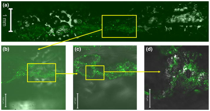
Figure 6 shows confocal images of the cell migration path in Sample C. It is seen that the cells formed 3D cellular clusters inside the porous structure. As they migrated towards the higher FBS concentration, the cells also spread to any locations where they could reach. This evidence shows that the cells could grow well in the HIFU foamed porous structure and form 3D constructs. This type of 3D constructs could mimic in vivo cellular behaviors more realistically.
Fig. 6.
Confocal microscope images of Sample C. Yellow boxes show the regions magnified in the subsequent images. Green color indicates the GFP cells. The scale bar is 1 mm, 500 μm, 200 μm, and 50 μm for (a), (b), (c), and (d), respectively
Cell attachment to the porous structure was observed using the scanning electron microscope. Figure 7 shows the SEM images of a cross section in the cell migration path. It is clearly seen that the cells formed 3D clusters and attached to the surface of the pores. These clusters could be traced along the migration path, indicating that the cells were migrating in groups, rather than individually. The red circles in the images show where the cell clusters were.
Fig. 7.
SEM images of the migrated cells inside the porous structure. The red circles show the cell clusters. The scale bars are (a) 100 μm, (b) 20 μm, and (c) 5 μm
Much of the research on 3D cell migration has been done using gel-based materials. For example, it was found that about 40% of the invasive breast cancer cells MDA-MB-231 could migrate though Matrigel mediated by 20% FBS (Chaw et al. 2007). Gel-based assays provide a good way to track individual cell movement in short distances. However, cells encapsulated in gels are not able to move a relative long distance. The migration distances reported in the literature were in 100–500 μm range (Chaw et al. 2007; Diao et al. 2006; Lee et al. 2008). This could be in part due to the confinement of cells and short diffusion path of chemicals in gels. The 3D cell migration study using a porous channel is a new concept. In our study, long distance cell migration (>1 mm) was clearly observed. The number of cells spontaneously migrated were much less than that of induced. This is beneficial for detecting the effects of chemoattractants.
3.2 Concentration gradient through the porous region
The cell migration observed above is believed due to the concentration gradient of FBS in the porous channel. A one-dimensional diffusion model is thus developed in order to understand the FBS gradient. As shown in Fig. 8, it is considered that the FBS solute with an initial concentration c0 at the source diffuses to the sink under the driving force of the concentration difference. Since there is no flow in the porous channel, we assume that the process is pure diffusion and there is no convection effect.
Fig. 8.
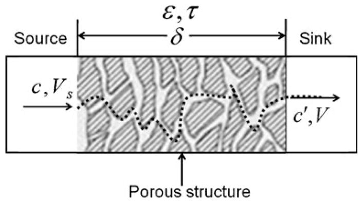
A schematic of the porous diffusion model
This diffusion process can be described by Fick’s first law. Consider that the volume of the source Vs and that of the sink V are the same. The following equation can be obtained (Christie 2003)
| (1) |
where c and c′ are the instantaneous concentrations of solute A in the source and sink, respectively, ε is the void fraction of the porous structure (also known as the effective porosity), τ is the tortuosity of the porous structure, δ is the distance between the source and sink, Ac is the limiting cross sectional area of the porous channel, DAB is the diffusion coefficient of solute A in solvent B, which is water in this study, and t is time. The initial concentrations of solute A in the source and sink wells are denoted as c0 and c0′. In our experiments, c0′ was equal to zero, since there was no FBS in the sink well.
When the solutes are large biomolecules such as proteins and nuclear acids with molecular weights larger than 1,000, a semi-empirical equation of Polson can be used to evaluate the diffusion coefficient as follows (Polson 1950).
| (2) |
where μB is the viscosity of the solvent, MA is the molecular weight of the solute, and T is the temperature of the solution in K. In our experiments, the molecular weight of BSA, which is the dominant component of FBS, was used to approximate that of FBS. Hence, MA was chosen to be 67,500.
Deff is an effective diffusion coefficient of the solute in a porous media, which can be defined as
| (3) |
The effective volume of the solution inside the porous structure is assumed to be much smaller than the source volume Vs. Therefore, the solute concentration in the sink well can be obtained as
| (4) |
Substitute Eq. 4 into Eq. 1 and integrate. We obtain the following
| (5) |
Define λ as the system time constant,
| (6) |
Equation 5 can be simplified as
| (7) |
Equation 7 can be used to predict the concentration variation inside the porous region with diffusion length and time. The parameters used in the prediction are summarized in Table 1. The determinining factor of the simulation results was the effective diffusion rate Deff of BSA through the porous channel. From Eqs. 2 and 3, Deff used in our study was obtained as 2.35×10⁻¹¹ m2·s−1. This value agrees well with what was experimentally determined under similar solute and geometrical conditions (Fardet et al. 1998). Using a diffusion cell consisting of two well-stirred compartments separated by a porous protein membrane, Fardet et al. has experimentally determined the effective BSA diffusion rate at 310 K as 1.84×10⁻¹¹ m2·s−1. The pore size of the membrane in their study was in the range of 0.5–30 μm. The porosity was ~45% and the tortuosity was ~2.
Table 1.
Parameters used in the diffusion model
| Parameters | Values |
|---|---|
| T | 310 K |
| μB(310K) | 0.695×10⁻³ Pa ·s |
| DAB | 1.03×10⁻¹⁰ m2·s−1 |
| ε | 0.4 |
| τ | 1.75 |
| Vs | 1.0×10⁻⁷ m3 |
| Ac | 2.0×10⁻⁵ m2 |
| c0 | 1 |
Figure 9 shows the prediction results in our study. It can be seen that it would take more than 100 h for the FBS solute concentration to reach equilibrium in the sink well when the distance is 1 mm from the source well. It would take longer if the diffusion distance is larger. In the experiments we conducted in this study, the cell culture media was changed every 48 h or sooner. Therefore, a significant concentration gradient was maintained between the two wells.
Fig. 9.
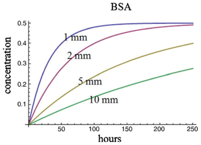
The estimated solute concentration in the sink well as a function of diffusion length and time. Initial concentration in the source well is assumed to be 1
Inside the porous channel, the concentration gradient is determined by the effective diffusion coefficient, Deff, which is a function of the material properties of the porous structure (ε, τ), as well as the solute, solvent, and temperature. It is therefore possible to manipulate the concentration gradient by changing the parameters of the porous structure. The porosity ε is determined by the average porous size and the uniformity of the porous structure. Tortuosity τ is related to porosity ε in an approximate relation. For example, the approximate values of τ for different values of ε are as follows: ε=0.2, τ=2.0; ε=0.4, τ=1.75; ε=0.6, τ=1.65 (Satterfield 1970). In the foaming process we used, we have found that a larger foaming power and higher scanning speed would result in a smaller pore size. A lower power combined with a low scanning speed would yield larger pore size. Hence by controlling the foaming process we can obtain a desirable diffusivity Deff.
4 Conclusions
A porous 3D cell culture device has been developed for cell migration studies. The device has a porous channel that was fabricated using a HIFU foaming process. Significant cell migration across 5 mm porous channel was observed when the biochip device was seeded with metastatic M4A4-GFP breast cancer cells induced by 20% fetal bovine serum (FBS) for 1–2 weeks. Cells formed colonies in the porous structure as they migrated towards the FBS. A diffusion model was developed to evaluate the concentration gradient inside the porous structure. Using a porous channel for the cancer migration study is a novel approach. The fabricated porous biochip device is expected to find many applications in cancer cell migration, invasion, and drug screening.
Acknowledgments
This research was partially supported through grants from NIH (5R21EB008573) and NSF (CMMI0348767). We acknowledge Mr. Nicholas Vaccaro for help in SEM imaging and Mr. Zhe Xu for help in machining. SEM and confocal images were taken at University of Washington Nanotechnology User Facility Center.
Contributor Information
Liang Ma, Department of Mechanical Engineering, University of Washington, Seattle, WA 98195-2600, USA.
Changchun Zhou, Department of Mechanical Engineering, University of Washington, Seattle, WA 98195-2600, USA.
Biaoyang Lin, Swedish Medical Center, Seattle, WA 98122, USA, Department of Urology, University of Washington, Seattle, WA 98195, USA.
Wei Li, Email: weiwli@austin.utexas.edu, Department of Mechanical Engineering, University of Washington, Seattle, WA 98195-2600, USA, Department of Mechanical Engineering, The University of Texas at Austin, Austin, TX 78712, USA.
References
- Al-Sokanee ZN, Toabi AA, Al-Assadi MJ, Alassadi EA. The drug release study of ceftriaxone from porous hydroxyapatite scaffolds. AAPS PharmSciTech. 2009 doi: 10.1208/s12249-009-9265-7. [DOI] [PMC free article] [PubMed] [Google Scholar]
- Boyden S. The chemotactic effect of mixtures of antibody and antigen on polymorphonuclear leucocytes. The Journal of Experimental Medicine. 1962;115:453–466. doi: 10.1084/jem.115.3.453. [DOI] [PMC free article] [PubMed] [Google Scholar]
- Brackenbury WJ, Djamgoz MB. Nerve growth factor enhances voltage-gated Na+ channel activity and transwell migration in Mat-LyLu rat prostate cancer cell line. Journal of Cellular Physiology. 2007;210:602–608. doi: 10.1002/jcp.20846. [DOI] [PMC free article] [PubMed] [Google Scholar]
- Chambers AF, Groom AC, MacDonald IC. Dissemination and growth of cancer cells in metastatic sites. Nature Reviews Cancer. 2002;2:563–572. doi: 10.1038/nrc865. [DOI] [PubMed] [Google Scholar]
- Chaw KC, Manimaran M, Tay FE, Swaminathan S. A quantitative observation and imaging of single tumor cell migration and deformation using a multi-gap microfluidic device representing the blood vessel. Microvascular Research. 2006;72:153–160. doi: 10.1016/j.mvr.2006.06.003. [DOI] [PubMed] [Google Scholar]
- Chaw KC, Manimaran M, Tay FE, Swaminathan S. Matrigel coated polydimethylsiloxane based microfluidic devices for studying metastatic and non-metastatic cancer cell invasion and migration. Biomedical Microdevices. 2007;9:597–602. doi: 10.1007/s10544-007-9071-5. [DOI] [PubMed] [Google Scholar]
- Cho SH, Oh SH, Lee JH. Fabrication and characterization of porous alginate/polyvinyl alcohol hybrid scaffolds for 3D cell culture. Journal of Biomaterials Science, Polymer Edition. 2005;16:933–947. doi: 10.1163/1568562054414658. [DOI] [PubMed] [Google Scholar]
- Christie JG. Transport Processes and Separation Process Principles. 4. Prentice Hall; 2003. [Google Scholar]
- Decaestecker C, Debeir O, Van Ham P, Kiss R. Can anti-migratory drugs be screened in vitro? A review of 2D and 3D assays for the quantitative analysis of cell migration. Medicinal Research Reviews. 2007;27:149–176. doi: 10.1002/med.20078. [DOI] [PubMed] [Google Scholar]
- Diao J, Young L, Kim S, Fogarty EA, Heilman SM, Zhou P, Shuler ML, Wu M, DeLisa MP. A three-channel microfluidic device for generating static linear gradients and its application to the quantitative analysis of bacterial chemotaxis. Lab on a Chip. 2006;6:381–388. doi: 10.1039/b511958h. [DOI] [PubMed] [Google Scholar]
- Even-Ram S, Yamada KM. Cell migration in 3D matrix. Current Opinion in Cell Biology. 2005;17:524–532. doi: 10.1016/j.ceb.2005.08.015. [DOI] [PubMed] [Google Scholar]
- Fardet A, Hoebler C, Djelveh G, Barry JL. Restricted bovine serum albumin diffusion through the protein network of pasta. Journal of Agricultural and Food Chemistry. 1998;46:4635–4641. [Google Scholar]
- Huang H, Oizumi S, Kojima N, Niino T, Sakai Y. Avidin-biotin binding-based cell seeding and perfusion culture of liver-derived cells in a porous scaffold with a three-dimensional interconnected flow-channel network. Biomaterials. 2007;28:3815–3823. doi: 10.1016/j.biomaterials.2007.05.004. [DOI] [PubMed] [Google Scholar]
- Lauffenburger DA, Horwitz AF. Cell migration: a physically integrated molecular process. Cell. 1996;84:359–369. doi: 10.1016/s0092-8674(00)81280-5. [DOI] [PubMed] [Google Scholar]
- Lee SH, Moon JJ, West JL. Three-dimensional micropatterning of bioactive hydrogels via two-photon laser scanning photolithography for guided 3D cell migration. Biomaterials. 2008;29:2962–2968. doi: 10.1016/j.biomaterials.2008.04.004. [DOI] [PMC free article] [PubMed] [Google Scholar]
- Li Z, Gunn J, Chen MH, Cooper A, Zhang M. On-site alginate gelation for enhanced cell proliferation and uniform distribution in porous scaffolds. Journal of Biomedical Materials Research Part A. 2008;86:552–559. doi: 10.1002/jbm.a.31596. [DOI] [PubMed] [Google Scholar]
- Lin YJ, Yen CN, Hu YC, Wu YC, Liao CJ, Chu IM. Chondrocytes culture in three-dimensional porous alginate scaffolds enhanced cell proliferation, matrix synthesis and gene expression. Journal of Biomedical Materials Research Part A. 2009;88:23–33. doi: 10.1002/jbm.a.31841. [DOI] [PubMed] [Google Scholar]
- Niggemann B, Drell TL, IV, Joseph J, Weidt C, Lang K, Zaenker KS, Entschladen F. Tumor cell locomotion: differential dynamics of spontaneous and induced migration in a 3D collagen matrix. Experimental Cell Research. 2004;298:178–187. doi: 10.1016/j.yexcr.2004.04.001. [DOI] [PubMed] [Google Scholar]
- Polson The some aspects of diffusion in solution and a definition of a colloidal particle. J Phys Colloid Chem. 1950;54 [Google Scholar]
- Ponath PD, Wang J, Heath H. Transwell chemotaxis. Methods in Molecular Biology. 2000;138:113–120. doi: 10.1385/1-59259-058-6:113. [DOI] [PubMed] [Google Scholar]
- Ruoslahti E. How cancer spreads. Scientific American. 1996;275:72–77. doi: 10.1038/scientificamerican0996-72. [DOI] [PubMed] [Google Scholar]
- Ruster B, Grace B, Seitz O, Seifried E, Henschler R. Induction and detection of human mesenchymal stem cell migration in the 48-well reusable transwell assay. Stem Cells and Development. 2005;14:231–235. doi: 10.1089/scd.2005.14.231. [DOI] [PubMed] [Google Scholar]
- Satterfield CN. Mass Transfer in Heterogeneous Catalysis. MIT; Cambridge: 1970. [Google Scholar]
- Uttarwar M, Aswath P. Fabrication of porous, drug-releasing, biodegradable, polymer scaffolds for sustained drug release. Journal of Biomedical Materials Research Part B: Applied Biomaterials. 2008;87:121–131. doi: 10.1002/jbm.b.31077. [DOI] [PubMed] [Google Scholar]
- Wang H, Li W. A novel passive polymeric micromixer fabricated using selective ultrasonic foaming. Journal of Micromechanics and Microengineering. 2007;17:1835–1842. [Google Scholar]
- Wang H, Li W. Selective ultrasonic foaming of polymer for biomedical applications. ASME Transaction Journal of Manufacturing Science and Engineering. 2008;130(2):021004-1–021004-9 . [Google Scholar]
- Webb SE, Pollard JW, Jones GE. Direct observation and quantification of macrophage chemoattraction to the growth factor CSF-1. Journal of Cell Science. 1996;109(Pt 4):793–803. doi: 10.1242/jcs.109.4.793. [DOI] [PubMed] [Google Scholar]
- Zicha D, Dunn G, Jones G. Analyzing chemotaxis using the Dunn direct-viewing chamber. Methods in Molecular Biology. 1997;75:449–457. doi: 10.1385/0-89603-441-0:449. [DOI] [PubMed] [Google Scholar]


