

Abstract
Reconfigurable arrays offer an advantage over traditional ultrasound arrays because of their flexibility in channel selection. To improve ultrasound beamforming and coverage through beam steering, we propose a hybrid beamforming technique to elongate the depth of focus of transmit beams and a method of element selection that improves steering capabilities that take advantage of array reconfigurability using annular rings. A local minimization technique to optimize the hybrid aperture is discussed in this paper. The chosen hybrid apertures covering four focal zones result in improved range in depth of focus when compared with pure spherical beams via point spread functions (PSF) and lesion signal-tonoise ratio (LSNR) calculations. Improvements were statistically significant at focal depth extremes. Our method of beam steering utilizing a quantized phase delay selection to minimize delay errors indicated better performance by removing an artifact present with traditional ringed element selection.
I. Introduction
Annular array focusing is a viable alternative to linear and cylindrical focusing because it provides a large improvement in elevational beam width compared with conventional linear arrays without requiring a large number of channels [1]. Early studies showed that annular arrays with as few as 12 rings produce good quality images [2].
Reconfigurable arrays are especially advantageous with annular and other configurations because subelements are dynamically linked together to form larger elements and can be adjusted to optimize the beam for steering and partial aperture imaging at the edges of the scanning area [3]-[5]. Activation of subelements is electronically moved across the aperture for precise and accurate beamforming. Not only are fewer channels needed, but this technology eliminates mechanical error and failures and electronic motor noise which are prevalent when translating linear arrays for a 3-D volume data set, thereby avoiding unnecessary degradation in image spatial fidelity and SNR [6].
The reconfigurable array concept allows us to take advantage of linear and other symmetrical beamforming as well. For instance, axicon focusing can be easily implemented with this array technology. Axicon focusing has been investigated in optics [7], [8] along with various acoustical studies [9]-[12]. Axicon focusing is advantageous because the beams maintain a constant width of the main lobe over the length of the beam, allowing for a large depth of focus. However, there is considerable side lobe energy beyond the main axis that has prevented practical use of axicon focusing in pulse echo imaging. An alternative to long depth of focus encompasses variations of the non-diffracting solution to the wave equation [13], [14]. These non-diffracting beams also propagate with a constant beam width over a long distance. Nevertheless, they consist of energy off-axis that requires suppression for high resolution and high contrast imaging. Other variations such as a Lorentz resonance curve delay have also been investigated [15].
In this paper, we will develop methods to improve straight beamforming and beam steering by taking advantage of array reconfigurability for breast imaging. We propose a method of optimizing such an aperture that utilizes spherical and conical focusing to produce a transmit beam with an extended depth of focus while suppressing much of the side lobe energy usually associated with axicon focusing. A simple hybrid aperture will be investigated that takes advantage of the reconfigurability of the 2-D aperture because it can be easily achieved in annular configurations. This paper will explain aperture choice through beam optimization and compare the optimized beams with purely spherical analogs. We will also examine the selection of different elements for steering to improve beam quality.
II. Materials and Methods
A. Transmitted Beam Optimization
To optimize the beam, we seek to quantify limitations that directly affect ultrasound image quality. Instead of evaluating grayscale ultrasound images, physical limitations that influence image fidelity will be investigated. Performance metrics have been defined and used before to assess quality of ultrasound scanners by evaluating key characteristics of high-quality images such as narrow beam width and deep penetration into soft tissue [16]. In this paper, we proceed in a similar fashion and introduce slightly more complex cost functions to determine aperture choice that aim to minimize beam width over the entire depth of field while penalizing clutter energy.
We propose a hybrid transmit aperture divided into an inner, spherical portion and an outer, conical, or axicon, portion. This focusing elongates the beam, preserving beam width while minimizing side lobe energy that accompanies conical focusing. To minimize phase distortion, the delays are matched at the edge between the spherical and conical aperture. We refer to this technique as hybrid beamforming for the rest of the paper.
For the proposed hybrid aperture, there are multiple parameters that affect beam quality, including the size of the two apertures, angle of the conical beam (φ), and focusing depth of the spherical beam (zs). The parameters for aperture selection are shown in Fig. 1. We label the radius at which the spherical and axicon apertures intersect r1 and the radius of the entire aperture r2. Axicon fraction is defined as the ratio of the axicon to the spherical aperture:
| (1) |
Fig. 1.
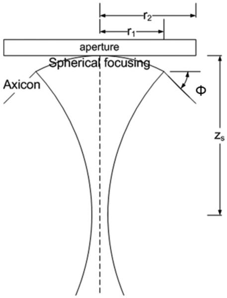
Diagram of hybrid focusing and parameters. Aperture is a 2-D reconfigurable array implementing hybrid annular array shown in cross section, containing the central axis of the array.
Beams of narrow main lobe width translate to narrow PSFs, or high resolution and sharp borders where they actually are sharp. Beams with low side lobe and clutter energy result in better CNR, especially when imaging anechoic lesions [17]. Thus, low side lobe and clutter energy contribute to improved detectability of large, low-contrast targets [18], as well as improved contrast in what should be extremely high-contrast objects such as large, simple cysts. The width at various levels below the peak of the PSF has been chosen to describe the effective beam width for pulse-echo imaging. The −6 dB beam width, or full-width at half-maximum is most common, but the −20 dB width [19] has been recommended by some as being more useful in gray scale imaging. There is no one, best descriptor of beam width profiles whose shapes can vary, but it is possible to avoid extreme beam shapes. To optimize this hybrid beam over an extended depth range, we implemented an initial closed form cost function that minimizes, for a given transmit pulse, the beam width at two levels over a range of depths:
| (2) |
The ultrasound beam widths will be determined as a function of depth via numerical simulation. Given a simulated beam, this cost function integrates the −6 and −20 dB beam ω over the depth range, z1 to z2, where the beam maintains > −12 dB of the peak signal. The integration term includes a z term to place emphasis on the beam width at deeper depths as sensitivity decreases as a function of depth. Another measure of beam centrality, or the amount of clutter energy in a beam, is the energy ratio, the fraction for the energy in the −6 dB beam width at depth z as a percent of the total energy passing through a plane at z and normal to the beam. We place a restriction on the useable range of a given transmission that this energy ratio be maintained at ± 3% from the average, typically a value around 0.95. In other words, approximately 95% of the energy of the beam at each depth is located within the 6 dB beam width. Depths at which this threshold is not met are removed from the integration range. Because the 6 dB and 20 dB integrations are naturally biased because of the absolute beam width value, they are both normalized by their corresponding spherical Bessel beam width at the spherical focus, as indicated by W6 and W20. By minimizing the S metric, we seek the beam with the best combination of narrow beam width over a long depth range (z2 − z1), which correlates to good lateral resolution over the entire depth of focus.
S(ω, z) serves as the core function for minimization of the main lobe of the hybrid transmit beams, taking into account beam widths and depth of penetration which directly affects the PSF and image resolution. We add another criterion to the minimization factor that will limit energy dispersion of a beam, or the off-axis side lobe and clutter energy that leads to degradation of image contrast. This metric is especially useful for separability when S values alone fall within a small range of each other. The acoustic power of a beam is centralized if the first moment of intensity is small, so we seek to minimize the ratio of the first to zeroth moment of the intensity at z:
| (3) |
The moments are calculated and averaged over the depth range of the beam. R represents the distance from the z-axis, which in these simulations will correlate to the center of the beam because there is no steering involved. Because we are dealing with symmetric array beamforming, r may be substituted with x, or the lateral axis. Smaller T values correlate to less off-axis energy and higher contrast images, and vice versa. When varying axicon angle, we will add the first moment at the focal depth as it provides a good measure of side lobe energy.
Using a 7.5-MHz, 185-μm pitch array, beams with varying parameters of axicon angle φ, spherical aperture radius r1, axicon aperture radius r2, and spherical focal depth zs were simulated with Field II ’s engine [20]. Axicon angle φ was varied from 12.5° to 20° along with aperture outer radius r2 ranging from 2 to 10 mm with axicon fractions A of 0.1 to 0.5. Spherical focusing depth relative to conical focusing depth was examined as well. With the combined minimization techniques, four optimized apertures were chosen via a semi-automated algorithm to cover a depth of 4.5 cm, coverage typical for breast imaging.
B. Comparison With Purely Spherical Beams
These apertures were compared with purely spherical beams via their point spread functions (PSFs) by examining beam width and axial amplitude versus depth. Side lobe energy was also assessed with six instances of 3-mm anechoic spherical void phantoms. Lesion detectability can be quantified with lesion signal-to-noise ratio (LSNR), computed as [21], [22]:
| (4) |
where μ and σ corresponded to the mean and standard deviation, respectively. Each scattering phantom consisted of 10 000 scatterers/cm3 as the minimum recommended by Oostervald et al. for fully developed Rayleigh statistics [23]. To calculate the PSF and LSNR for both spherical and hybrid apertures, we simulated pulse-echo imaging with dynamic receive focusing to mirror a practical, clinical setting. Statistical significance was investigated using a two-sided student’s t-test.
C. Beam Steering
Beam steering can be achieved with reconfigurable arrays by placing the center of the annuli directly in front of the focus [4]. As steering usually requires finer sampling, delay approximation errors cause detectable artifacts when steering with reconfigurable configurations. To improve steered beam quality, we chose to link subelements together based on their corresponding delay lines instead of subelement location. For instance, if we have 32 channels, we first compute the ideal delay for each subelement and then quantize them to 32 values. Each subelement that shares the same quantized value will be linked to the same channel.
In a reconfigurable array, subelements are connected and disconnected to each other and to system channels via an underlying switch matrix [3]. The groups of subelements that form an element must have an access point to the channel for transmitting and receiving signals. The number of access points in the reconfigurable array is limited electronically because more switches would be needed for additional access points, which incrementally increases the complexity of the hardware. Our quantization scheme ensures that linked subelements can form a ring without relying on a dense distribution of access points across the array by making sure subelements that share the same delay are mostly contiguous throughout the entire array. For each subelement, a close access point on the order of 5 to 6 subelements away would be used to minimize propagation delays from access point to subelement.
To test our technique, we simulated one-way transmit beams using two configurations: placing the center of the annular array at the point in front of the focus in the x-y plane, and by dividing the array into elements based on their delay values as illustrated in Fig. 2. With 128 channels and a 20.1-mm diameter, 150-μm pitch aperture, the beam was focused 4 cm deep at a central frequency of 5 MHz and steered 45°.
Fig. 2.

To illustrate aperture ring selection, a 128-ring aperture steered 45° is shown. Each ring is linked to a different channel input delay. Ring shape was determined based on quantization of time delays to minimize artifacts caused by phase error.
III. Results
A. Beam Optimization
Optimization of aperture size was first performed to determine the ideal f-number operation given our array properties. We examined the beam widths found from the PSFs of spherical focusing simulations as a function of aperture diameter. The best aperture at each depth z corresponds to the smallest beam-width difference. The best results were obtained when maintaining an f-number of approximately 1.5 as shown in Table I. For instance, when focusing at 28 mm, the 18 mm aperture gave the best results. This f-number was used for aperture size in dynamic receive focusing.
TABLE I.
Beamwidth Difference (w(z) − w(22)) at Different Focusing Depths
| Focal depth z (mm) |
Aperture (mm) |
|||
|---|---|---|---|---|
| 18 | 20 | 24 | 26 | |
| 28 | −0.192 | −0.150 | 0.149 | 0.151 |
| 30 | −0.012 | −0.027 | 0.105 | 0.158 |
| 32 | 0.001 | −0.010 | 0.052 | 0.146 |
| 34 | 0.023 | 0.003 | 0.030 | 0.127 |
| 36 | 0.062 | 0.029 | 0.003 | 0.061 |
| 38 | 0.066 | 0.016 | 0.014 | 0.070 |
For arrays with pitch greater than λ/2, steering angle must be limited to minimize grating lobe effects on image quality. To determine a suitable axicon angle for the hybrid aperture, different φs ranging from 12.5° to 20° were simulated with an aperture using axicon focusing with r1 = 2 mm and r2 = 3 mm. The spatial peak intensity of the axicon beam depends on the angle chosen and location of the inner and outer edges of the axicon, r1 and r2, which can be determined geometrically as it lies in between the depths at which the beams of the axicon overlap. We will refer to this point of maximum intensity of the axicon beam as the axicon central focus. An illustration showing the location of the axicon central focus with respect to the aperture is shown in Fig. 3.
Fig. 3.
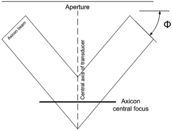
The axicon beam produced by the outer axicon ring aperture. The axicon central focus is defined as the spatial peak intensity of the beam, which is located between the intersection with the central axis of the beams normal to the axicon aperture from its inner and outer edges. Changing r1, r2, and angle φ will affect the location of the axicon central focus.
The spherical focusing depth was varied 3 to 5 mm deeper than the axicon central focus to improve the uniformity of the beam width and sensitivity with depth. The latter criterion was given more weight at the deepest focal zones where sensitivity is a problem. Focusing the spherical aperture beyond the axicon central focus produces a longer beam along the entire focal zone than would a shorter spherical focal point with a slightly larger beam width. An initial small aperture radius of 3 mm was chosen to not only reduce simulation time, but also to minimize the differences between depth range covered due to changing axicon angle.
The ideal axicon angle φ was found to be approximately 15° for this beamforming implementation as depicted in Fig. 4. To determine optimal axicon fraction A, we varied aperture size r2 from 2 to 10 mm with A ranging from 0.1 to 0.5 and evaluated our cost functions.
Fig. 4.
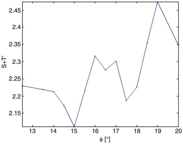
Minimization function and first energy moment averaged over beam and at focus for r1 = 2 mm and r2 = 3 mm aperture over various axicon angles.
As seen in Fig. 5, the optimal axicon fraction A was found to be approximately 0.25. With a starting axicon angle φ of 15° and A of 0.25, we proceeded to optimize various apertures to cover a depth of 4.5 cm by varying the given parameters φ and A along with spherical focal point zs. Four apertures were then chosen to best cover this range. The chosen parameters and focal regions covered by each aperture are delineated in Table II.
Fig. 5.
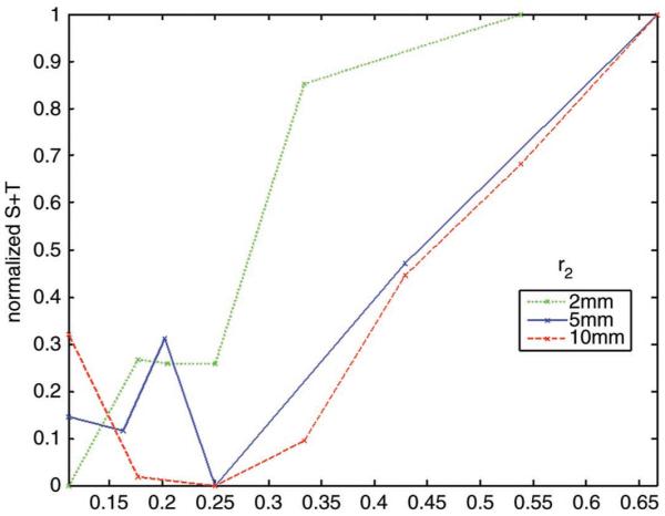
Minimization function varying axicon fraction A over different total aperture radii, r2. The best value found for A was approximately 0.25.
TABLE II.
Chosen Parameters for Each Locally Optimized Aperture
| Aperture | Inner axicon edge r1 (mm) |
Outer axicon edge r2 (mm) |
Axicon angle φ (°) |
Spherical focal depth zs (mm) |
Starting beam depth z1 (mm) |
Ending beambreak/>depth z2 (mm) |
|---|---|---|---|---|---|---|
| 1 | 1.5 | 2 | 15 | 10 | 2 | 17 |
| 2 | 4.4 | 5.5 | 15 | 22 | 15 | 27 |
| 3 | 6.5 | 7.8 | 15 | 31 | 24 | 37 |
| 4 | 8 | 10 | 14.5 | 39 | 31 | 46 |
B. Comparison With Purely Spherical Beams
The PSF of each of the four hybrid apertures was computed and compared with purely spherical apertures at corresponding depths. The PSF of the hybrid apertures at the edges of each focal zone showed higher sensitivity and better beam width when compared with the spherical apertures. The PSF and corresponding axial waveforms for the second and fourth aperture are shown in Fig. 6. Relative amplitudes are revealed in the waveforms.
Fig. 6.

Point spread function with 40 dB dynamic range and axial amplitude comparison for closest and farthest aperture. The corresponding central A-line is plotted on each side. The axial amplitude of the hybrid apertures shows that they outperform the spherical at the lower depths for each aperture.
LSNR was calculated for comparison using anechoic void phantoms. Six unique iterations were performed at different depths for each aperture, with P-values showing statistical significance at the focal depth extremes. The differences between the hybrid and spherical apertures at the focus were insignificant. Compared with beams using spherical focusing, the hybrid beams produced an elongated, more uniform beam over the range of depths. The average LSNR for spherical and hybrid apertures calculated at specific depths are shown in Table III along with the P-values.
TABLE III.
LSNR Calculations for Spherical and Hybrid Apertures Along With P-Values for Statistical Difference
| Depth (mm) | LSNRs (dB) | LSNRh (dB) | P-value |
|---|---|---|---|
| 13 | 4.61 | 6.28 | <0.0001 |
| 19 | 7.25 | 7.84 | 0.4126 |
| 25 | 4.10 | 5.72 | <0.0001 |
| 28 | 5.71 | 5.78 | 0.893 |
| 33 | 4.97 | 7.52 | <0.0001 |
| 37 | 8.51 | 8.31 | 0.624 |
| 44 | 6.41 | 7.69 | <0.0001 |
C. Beam Steering
By minimizing the delay errors for each subelement, we obtained a better quality beam by eliminating the eagle wing artifact found with the previous method using traditional annular rings. The beams shown in Fig. 7 are C-scans located in the elevational and lateral plane (radial plane) perpendicular to the steered beam.
Fig. 7.

C-scan display on a 40-dB scale of the PSF of a beam steered at 45° using traditional rings (top) and rings with subelements selected by quantization (bottom). The large artifact on the top image caused by phase delay error is removed.
IV. Discussion
A. Beam Optimization
For practicality, we chose to proceed with the minimization in a sequential manner. This can lead to local minima, requiring additional searches if results are unsatisfactory. The first parameter examined was φ, or axicon angle, because this parameter strongly affects how the other parameters should be chosen as well. The angles were varied from 12.5° to 20° in half-degree increments. Initial results shown in Fig. 4 showed that beams constructed with φ = 15° demonstrated a good balance between side lobe energy and depth coverage for deeper foci and was chosen as the initial approximate angle for aperture formation.
If we examine the beams closely, those with φ = 20° yielded a large amount of side lobe energy, whereas beams with φ = 12.5° had a much wider beam width, both of which would contribute to an increase in our minimization functions which favor narrower beam width and less side lobe clutter. Although angle sampling was relatively coarse, the tradeoff between side lobe energy and beam width is observed as encountered in traditional conical focusing.
Overall aperture was guided by experience with linear and phased arrays and the observation that, with our subelement geometry, the image quality factors deteriorated for f-numbers less than 1.5, as shown in Table I. We also found that using an aperture larger than 22 mm resulted in worse overall beam width, most likely caused by excessive phase cancellation effects from focusing coming from the outer edges of the aperture, resulting in destructive interference and an overall decreased focusing effect.
To determine an optimized aperture, aperture size r2 was varied from 2 to 10 mm and axicon fraction A from 0.1 to 0.5. Apertures with large A showed too much energy outside the main beam; this also resulted in a discontinuous jagged beam for which one could distinguish between the spherical and axicon beam. When A gets too small, the beam starts to resemble the purely spherical beam, thereby nullifying the hybrid focusing advantage. The optimized axicon portion was found to be approximately 0.25 of its spherical counterpart to produce an optimized, elongated beam for greater depth range. The exception, shown in Fig. 5, is at the smallest, 2 mm, aperture. This is most likely attributable to the minute differences obtained in beam width and range for such a small aperture, functioning largely in the near field. As A increased in value, the range and beam width difference was insufficient to form a function with a minimum.
The final parameter for minimization was zs, or spherical focal depth. zs was varied 2 to 5 mm beyond the depth of the axicon central focus for optimization. Ideally, we strove to focus as deeply as possible to extend beam range while preserving a narrow central beam. For all four apertures, the optimal depth choice was found to be approximately 3 mm beyond the axicon central focus. Exceeding this value produced beams with high side lobe energy caused by interference between the two different focusing techniques.
Although the choice of apertures to cover our chosen depth relies on these optimized parameters, it is important to note that aperture size also influences depth selection. This occurs because depth coverage of a ringed axicon with axicon angle φ-fixed focusing is directly related to axicon fraction A and aperture size r2. Thus, the size of each optimized aperture needs to be chosen accordingly to cover the desired range along with optimized parameters of φ, A, and spherical focus zs. Although φ, A, and zs were not optimized for each aperture and depth setting chosen, we did check that the image quality cost functions were at least at local minima over these parameters for each final aperture and focal range. To illustrate, we have included the surface of the cost function for selecting the fourth aperture in Fig. 8. We ensured that each chosen aperture was located at the minimum of our functional, providing a good combination of narrow beam width over a long depth with suppressed clutter energy given the axicon fraction A, spherical focus zs, and axicon central focus parameters.
Fig. 8.
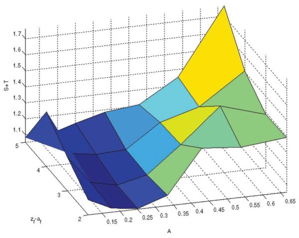
Surface of minimization function for aperture at deepest focal zone is shown. The chosen aperture falls within the valley signifying at least a local minimum of our cost functional.
B. Comparison With Purely Spherical Beams
We compared the hybrid apertures’ performance with standard spherically focused beams. The PSFs showed that the purely spherical beams have a narrower beam width at the focus. This is expected because spherical focusing concentrates most of its energy at the focus. However, the PSF of the hybrid beams sustained better beam width at the focal depth extremes. The hybrid apertures excel at these locations because they direct energy equally in the main lobe at all depths in the focal zone. The hybrid beams covered 1.2 to 1.5 cm within a −12 dB threshold signal, whereas the purely spherical beams averaged 0.8 to 1 cm.
The central A-line of the PSFs shown in Fig. 6 also demonstrates the increased sensitivity of the hybrid aperture at the deeper extreme of the focal zone. For instance, when comparing the maximum amplitude of the signal at depths of 12 and 14 mm, we observe larger amplitudes when using the hybrid aperture. The axial amplitudes of both the hybrid and spherical apertures for the first focal zone are plotted in Fig. 9. At 14 mm, the improvement of the hybrid aperture over the spherical aperture is approximately 8 dB. This improvement in sensitivity is important because of typical signal loss with depth in ultrasound imaging and thus it would be beneficial, especially in the breast imaging environment.
Fig. 9.
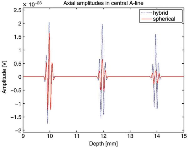
The A-line plots of the hybrid and spherical apertures are overlaid for the aperture of the first focal zone. At the lower depths, we see that the hybrid aperture is more sensitive compared with the spherical aperture.
To assess effects of side lobe and clutter energy, LSNR was calculated with multiple 3-mm spherical void phantoms at different depths encompassing the foci and beyond. We need to note that 10 000 scatterers/cm3 were used in these phantoms to speed up simulation time. Although the phantoms generated showed well-developed speckle, using more scatterers should lead to more consistent values. In our own experience, some improvement could be seen in going to higher densities but at impractical computation times. Furthermore, simulations were run on six unique scattering phantoms at each depth. Increasing the number of phantoms should also yield better statistics, albeit at the expense of simulation time.
Given the LSNR values in Table III, the purely spherical and hybrid beams both performed well at the focus because slight differences were statistically insignificant. This validates that side lobe and clutter energy usually accompanying axicon focusing were minimized with this beamforming method. At points beyond the focus, the performance of the hybrid beams was superior to their spherical equivalents, with t-values falling well below the threshold for P < 0.05. A composite image showing the PSFs and spherical void simulations of the four focal zones chosen are shown in Fig. 10. The benefit of the hybrid apertures is most apparent at the extremes of each focal zone. In some instances, the voids appeared murky when imaged with the spherical aperture but were well distinguished with the hybrid beam, e.g., at the 16 and 44 mm depths.
Fig. 10.

Point spread function and spherical void simulation comparison of spherical (left) and hybrid (right) apertures for a composite of the four focal zones over the entire 4.5-cm depth. The depth extremes of each of the four transmit focal zones of the spherical void simulations show higher sensitivity for the hybrid apertures.
We should note that both the hybrid and purely spherical focused apertures used in the simulations were not amplitude apodized. The outer portion of the optimal array apertures demonstrated in this paper is effectively phase apodized. Including amplitude apodization at the edge of a spherically focused array may yield similar results; a comparison would be interesting to investigate in future work.
Beam parameters that are most important to image quality include the lateral and axial resolutions, depth of field, contrast, and frame rate [24]. Our results suggest that hybrid beamforming results in improved image quality, producing a long, narrow beam that performs well at lower depths without sacrificing lateral resolution at the focus. This focusing scheme would also be advantageous in ultrasound transmit beams because fewer beams would be needed to cover the same depth range when compared with traditional spherical focusing. Being able to use fewer transmit pulses would allow an increase in frame rate and thus be especially favorable in applications limited by low frame rate such as Doppler and compound ultrasound imaging.
C. Beam Steering
Beam steering is useful to get extra information when transducer scanning angle is limited. When steering with reconfigurable arrays, the improvement in beam quality is most noticeable in the C-scan because phase delay errors are pronounced at various angles from the central axis when steering. By quantizing the delays, the maximum error of any subelement is decreased and instead distributed evenly over all the subelements. This results in removing the large artifact present in regular ring selection caused by concentrated energy and spreading the side lobe energy around the PSF instead. We should note that there will still be grating lobes caused by insufficient array sampling at a large steering angle; however, we found that minimizing phase error delay via delay quantization reduces excess side lobe energy associated with grating lobes as well.
The resulting PSF of the steered beam also illustrates the inherent advantage of reconfigurable arrays. Because it uses annular focusing, the beam width in the lateral direction is similar to that in the elevational direction, leading to an isotropic PSF or resolution. This uniformity improves ultrasound image quality when compared with traditional linear arrays because there will be minimal volume averaging due to the elevational beam width.
V. Conclusion
The reconfigurability of 2-D arrays affords beamforming flexibility with only a limited number of channels. Annular arrays represent a logical implementation of reconfigurable arrays. Although 12 elements were shown to be sufficient for annular array imaging [2] given the constraints of reliability of many coaxial cables under constant mechanical motion, we have found that increasing the number of elements drastically improves image quality. This reconfigurable concept can be extended to hybrid beamforming, which improves image quality for a given number of focal zones at the focal depth extremes when compared with spherical focusing. Hybrid beamforming can potentially increase frame rate as well because fewer transmit beams will be needed to cover the same depth range. Furthermore, reconfigurable arrays are also amenable to beam steering, which is critical in diagnostic ultrasound imaging for obtaining better beam coverage when translating the active aperture is not an option.
Biographies
Fong Ming Hooi received the B.S. degree in biomedical, electrical and computer engineering from Duke University, Durham, in 2005, and the M.S. degree in biomedical engineering in 2007 from the University of Michigan, Ann Arbor. Fong Ming is currently a graduate student in the biomedical engineering department of the University of Michigan. Her research interests include speed of sound signal processing and medical ultrasound imaging.
Kai E. Thomenius (M’66) was awarded the B.S., M.S., and Ph.D. degrees in electrical engineering and physiology from Rutgers University, New Brunswick, NJ, in 1968, 1970, and 1978, respectively.
His background includes both academic and industrial activities, including teaching and research at Rutgers University, Piscataway, NJ; Stevens Institute of Technology, Hoboken, NJ; and Rensselaer Polytechnic Institute (RPI), Troy, NY. He has worked for the U.S. Army Electronics Command at Ft. Monmouth, NJ, as an RF engineer. He has held research related positions in medical ultrasound since 1976 for Picker Ultrasound, Northford, CT; Elscint, Inc., Boston, MA; ATL/Interspec, Ambler, PA; and most recently GE Global Research in Niskayuna, NY, where he is currently a Chief Technologist in the Imaging Technologies Organization. In addition, he is an Adjunct Professor in the Electrical, Computer, and Systems Engineering Department at RPI. The focus of the industrial work has centered on ultrasound systems design, especially beam formation, miniaturization of ultrasound scanners, ultrasound bioeffects, and the design for ultraportable imagers. An additional focus deals with novel application of ultrasonic imagers.
Dr. Thomenius is a Fellow of the American Institute of Ultrasound in Medicine (AIUM), a member of the American Association of Physicists in Medicine, American Society for Echocardiography, Acoustical Society of America, IE, and the Society of Photo-Optical Instrumentation Engineers (SPIE). He is a member of the editorial board of the Ultrasonic Imaging Journal and serves as a reviewer of grant proposals for the National Institutes of Health and Department of Defense, and of articles for several ultrasound journals. In addition, he serves in the Technical Program Committees for IEEE Ultrasonics Symposium, the annual conference of the AIUM, and the Medical Imaging Conference of the SPIE.

Rayette Fisher received the B.S. and M.S. degrees in electrical engineering from the University of Missouri-Columbia in 1986 and 1987, respectively. She joined GE Global Research in 1987 as part of the Power Electronics Lab, where she worked on miniaturization and efficiency improvements of various communications satellite, fluorescent lighting, and healthcare imaging systems. She is currently a Senior Engineer at GE Global Research working in the Electronics Miniaturization Lab, where her recent work includes the design and packaging of large area sensor arrays for real-time, volumetric imaging applications.
Paul L. Carson (M’74) received the B.S. degree from the Colorado College, Colorado Springs, CO, and the M.S. and Ph.D. degrees from the University of Arizona, Tucson, AZ, in 1969 and 1971, all in physics. From 1971 to 1981, he served in the Department of Radiology at the University of Colorado Medical Center, Denver. Since 1981, he has served as associate professor, professor, and BRS Collegiate Professor in the Department of Radiology, and as a professor of Biomedical Engineering and member of the Applied Physics faculty, University of Michigan, Ann Arbor, MI. He was Director of Basic Radiological Sciences in Radiology from 1981 to 2008. His responsibilities have been in research, clinical support, and teaching of radiological sciences. Research interests include medical ultrasound (quantitative imaging, functional imaging, equipment performance, safety, and new or improved diagnostic and therapeutic applications), combined breast x-ray tomosynthesis/ultrasound, and photoacoustic tomography.
Dr. Carson is a Fellow, past vice president, and J. H. Holms Basic Science Pioneer Award Recipient of the American Institute of Ultrasound in Medicine and is a Fellow, Past President and 2008 Coolidge Award Recipient of the American Association of Physicists in Medicine. He is a Fellow of the Acoustical Society of America, the American College of Radiology, and the American Institute of Medical and Biomedical Engineering.
Contributor Information
Fong Ming Hooi, Department of Radiology, University of Michigan, Ann Arbor (fongming@umich.edu).
Kai E. Thomenius, GE Global Research, Niskayuna, NY.
Rayette Fisher, GE Global Research, Niskayuna, NY.
Paul L. Carson, Department of Radiology, University of Michigan, Ann Arbor (fongming@umich.edu).
References
- [1].Arditi M, Foster FS, Hunt JW. Transient fields of concave annular arrays. Ultrason. Imaging. 1981;3(1):37–61. doi: 10.1177/016173468100300102. [DOI] [PubMed] [Google Scholar]
- [2].Foster FS, Larson JD, Mason MK, Shoup TS, Nelson G, Yoshida H. Development of a 12 element annular array transducer for realtime ultrasound imaging. Ultrasound Med. Biol. 1989;15(7):649–659. doi: 10.1016/0301-5629(89)90173-7. [DOI] [PubMed] [Google Scholar]
- [3].Fisher R, Thomenius K, Wodnicki R, Thomas R, Cogan S, Hazard C, Lee W, Mills D, Khuri-Yakub B, Ergun A, Yaralioglu G. Reconfigurable arrays for portable ultrasound; Proc. IEEE Ultrasonics Symp.; 2005.pp. 495–499. [Google Scholar]
- [4].Cogan S, Fisher R, Thomenius K, Wodnicki R. 2B-1 Solutions for Reconfigurable Arrays in Ultrasound; Proc. IEEE Ultrasonics Symp.; 2006.pp. 116–119. [Google Scholar]
- [5].Thomenius K, Fisher R, Mills D, Wodnicki R, Hazard C, Smith L. Mosaic arrays using micromachined transducers. U.S. Patent 6 865 140. 2005 Mar 8;
- [6].Ultrasonics–Pulse–Echo Scanners–Part I: Techniques for calibrating Spatial Measurement Systems and Measurement of System Point Spread Function Response. 2006. IEC 61391-1. [Google Scholar]
- [7].McLeod JH. The axicon: A new type of optical element. J. Opt. Soc. Am. 1954;44(8):592–597. [Google Scholar]
- [8].Fujiwara S. Optical properties of conic surfaces. I. Reflecting cone. J. Opt. Soc. Am. 1962;52(3):287–291. [Google Scholar]
- [9].Patterson MS, Foster FS. Acoustic fields of conical radiators. IEEE Trans. Sonics Ultrason. 1982;29(2):83–91. [Google Scholar]
- [10].Burckhardt CB, Hoffmann H, Grandchamp PA. Ultrasound axicon: A device for focusing over a large depth. J. Acoust. Soc. Am. 1973;54(6):1628–1630. [Google Scholar]
- [11].Holm S. Bessel and conical beams and approximation with annular arrays. IEEE Trans. Ultrason. Ferroelectr. Freq. Control. 1998;45(3):712–718. doi: 10.1109/58.677615. [DOI] [PubMed] [Google Scholar]
- [12].Yamada K, Tasei K, Nakamura K. Weighted conical transducer for generation of Bessel-beam ultrasound. J. Acoust. Soc. Jpn. 1992;48(12):871–875. [Google Scholar]
- [13].Durnin J. Exact solutions for nondiffracting beams. I. The scalar theory. J. Opt. Soc. Am. 1987 Apr;4(4):651–654. [Google Scholar]
- [14].Lu J, Greenleaf J. Nondiffracting X waves-exact solutions to free-space scalar wave equation and their finite aperture realizations. IEEE Trans. Ultrason. Ferroelectr. Freq. Control. 1992;39(1):19–31. doi: 10.1109/58.166806. [DOI] [PubMed] [Google Scholar]
- [15].Umemura S, Azuma T, Miwa Y, Sasaki K, Sugiyama T, Hayashi T, Kuribara H. Non-cylindrical transmission focusing for large depth of field; Proc. IEEE Ultrasonics Symp.; 2002.pp. 1721–1724. [Google Scholar]
- [16].Pye SD, Ellis W, MacGillivray T. Medical ultrasound: A new metric of performance for grey-scale imaging; J. Physics: Conference Series; 2004.pp. 187–192. [Google Scholar]
- [17].Bushberg JT, Seibert JA, Leidholdt EM, Boon JM. The Essential Physics of Medical Imaging. 2nd ed. Lippincott, Willams & Wilkins; Philadelphia, PA: 1993. [Google Scholar]
- [18].Li PC, Odonnell M. Improved detectability with blocked element compensation. Ultrason. Imaging. 1994;16(1):1–18. doi: 10.1177/016173469401600101. [DOI] [PubMed] [Google Scholar]
- [19].Kossoff G. Analysis of focusing action of spherically curved transducers. Ultrasound Med. Biol. 1979;5(4):359–365. doi: 10.1016/0301-5629(79)90006-1. [DOI] [PubMed] [Google Scholar]
- [20].Jensen J, Svendsen N. Calculation of pressure fields from arbitrarily shaped, apodized, and excited ultrasound transducers. IEEE Trans. Ultrason. Ferroelectr. Freq. Control. 1992;39(2):262–267. doi: 10.1109/58.139123. [DOI] [PubMed] [Google Scholar]
- [21].Kofler JM, Madsen EL. Improved method for determining resolution zones in ultrasound phantoms with spherical simulated lesions. Ultrasound Med. Biol. 2001 Dec;27:1667–1676. doi: 10.1016/s0301-5629(01)00473-2. [DOI] [PubMed] [Google Scholar]
- [22].Kofler JM, Jr., Lindstrom MJ, Kelcz F, Madsen EL. Association of automated and human observer lesion detecting ability using phantoms. Ultrasound Med. Biol. 2005;31:351–359. doi: 10.1016/j.ultrasmedbio.2004.12.003. [DOI] [PubMed] [Google Scholar]
- [23].Oosterveld BJ, Thijssen JM, Verhoef WA. Texture of B-mode echograms: 3-D simulations and experiments of the effects of diffraction and scatterer density. Ultrason. Imaging. 1985 Apr;7:142–160. doi: 10.1177/016173468500700204. [DOI] [PubMed] [Google Scholar]
- [24].Lu J-Y, Zou H, Greenleaf JF. Biomedical ultrasound beam forming. Ultrasound Med. Biol. 1994;20(5):403–428. doi: 10.1016/0301-5629(94)90097-3. [DOI] [PubMed] [Google Scholar]