Abstract
We have developed pneumatic logic circuits and microprocessors built with microfluidic channels and valves in polydimethylsiloxane (PDMS). The pneumatic logic circuits perform various combinational and sequential logic calculations with binary pneumatic signals (atmosphere and vacuum), producing cascadable outputs based on Boolean operations. A complex microprocessor is constructed from combinations of various logic circuits and receives pneumatically encoded serial commands at a single input line. The device then decodes the temporal command sequence by spatial parallelization, computes necessary logic calculations between parallelized command bits, stores command information for signal transportation and maintenance, and finally executes the command for the target devices. Thus, such pneumatic microprocessors will function as a universal on-chip control platform to perform complex parallel operations for large-scale integrated microfluidic devices. To demonstrate the working principles, we have built 2-bit, 3-bit, 4-bit, and 8-bit microprecessors to control various target devices for applications such as four color dye mixing, and multiplexed channel fluidic control. By significantly reducing the need for external controllers, the digital pneumatic microprocessor can be used as a universal on-chip platform to autonomously manipulate microfluids in a high throughput manner.
Introduction
Since the early 1990’s, many innovative microfluidic lab-on-a-chip devices have been developed that analyze picoliters of fluid under controlled reaction conditions (1, 2). However, little of the anticipated impact of microfluidics has been realized possibly due to the gap between technology developers and technology users (3, 4) or to the complexity of the constructed devices. Many potential microfluidic applications often require the integration of a large number of valves, pumps, and other components, many of which need additional off-chip control equipment. Although recent technical advances in pneumatic microvalves (5) have enabled large-scale integration of microfluidic components to perform hundreds of operations in parallel by multiplexing control of embedded operational valves (5–8), the need for a large number of dedicated external control lines imposes practical limits on the portability and scalability of integrated microfluidic systems.
The complexity of controlling microfluidic devices can be simplified by adding on-chip fluidic logic networks to the devices (9). Much like the development of electronic logic gates simplified the construction and operation of complex electronic devices, pneumatic logic gates could considerably reduce the number of required off-chip controllers. Although analogous macroscale fluidic logic gates were developed back in the 1960s (10, 11), the nonlinearity from turbulent flows is not applicable to microfluidic systems (12). Various microfluidic logic gates operated on Boolean rules have been proposed to direct internal flows in complex networks and perform simple on-chip calculations (13–17). Although conceptually powerful, most of the developed microfluidic logic gates rely on different input/output types (15–17) and, therefore, the output cannot easily be used as an input to directly actuate subsequent logic gates. This non-cascadable nature inhibits further scaling and routing for more complex circuits. A more recent system using transistor-like pneumatic valves to form on-chip pneumatic demultiplexer circuits have been presented (9, 18). These structures do perform digital operations but decreases in the signal strength may occur during signal transportation and the calculations cannot be repeatedly performed without appropriate venting each time. Other approaches utilizing droplet-based input/output for logic gates (13, 14) exhibit excellent cascadability but construction of control platforms from these systems is difficult since the trajectories or existences of droplets cannot be used for actuation of active control components. Most importantly, no parallel operations have been achieved from serially-programmed input signals.
We have developed pneumatic logic circuits that are capable of performing various combinational and sequential logic calculations with binary pneumatic signals (atmosphere and vacuum). The logic circuits can produce cascadable outputs based on Boolean operations and, therefore, function as a complex pneumatic microprocessor. Using the circuits, a pneumatically encoded serial input can be decoded and used to simultaneously operate multiple pneumatic control valves. This decoding of a single input signal significantly reduces the need for external control valves.
Materials and Methods
Device Fabrication
The PDMS circuit devices were constructed using three separate layers. The first thin (~300μm) ‘control’ layer was situated at the bottom of the device and contained control channels to directly connect the pneumatic valves. It was also used to form the valve displacement chambers and the valve diaphragm membranes (~100μm thick) above the chambers. Inter-layer connecting holes were also drilled in the ‘control’ layer so that the holes could be open to the chamber or channels in the upper layer. The second ‘flow’ layer contained the main channel network. The main entrance of the input signal was built in the ‘flow’ layer, and vacuum/atmosphere ports and their connecting channels resided in this layer. Finally, the optional third ‘supply’ layer was composed of a large vacuum reservoir/channel to supply vacuum to multiple vacuum ports in the ‘flow’ layer simultaneously. The ‘supply’ layer was fabricated in a thick PDMS layer on the top of all other layers although it also could be situated at the bottom. A glass substrate is a good substitute for the ‘supply’ layer.
The devices were manufactured using standard multi-layer soft-lithographic techniques (19). The SU-8 master molds were fabricated by spinning the SU-8 2025 (MicroChem) resist on a bare silicon wafer and pre-baked on the hot plate for 5 min at the 65°C and for 20 min subsequently at the 95°C. Approximately 150 μm thick patterns could be obtained when the spin coating was done twice. After the exposure to 365 nm UV light, the coated wafer was post-exposure baked for 1 min at the 65°C and for 10 min subsequently at the 95°C. The successive development in SU-8 developer solution (MicroChem) resulted in the channel patterns with the desired thickness measured with a mechanical height gauge (Mitutoyo). Once the SU-8 master mold was prepared, a mixture of PDMS prepolymer and curing agent (9:1 w/w, Sylgard 184, Dow-Corning) was cast against the SU-8 master molds for the ‘flow’ and ‘supply’ layers and cured at 150°C for 15 min. The cured PDMS cast was carefully removed from the molds and diced into individual dies. To fabricate the ‘control’ bottom layer, channels were patterned with a 200 μm thickness, and a 10: 1 PDMS mixture was spincoated on the SU-8 mold to have a 300 μm PDMS layer. The bottom layer structure was also cured at 150°C for 15 min. After removing the cured PDMS layer from the mold, inlet/outlet holes and inter-layer connecting holes were drilled manually with a stainless steel blunt needle (Small Parts, Inc.). Finally, three individually fabricated layers were carefully aligned and reversibly bonded to each other.
Pressure Control and Measurements
The input signal inlet and clock signal inlet in the device were connected through stainless steel needle stub with tubing to a computer-controlled setup that consisted of two-way solenoid valves (Numatech). Each solenoid valve could turn on and off vacuum or atmospheric pressure in a pulsatile manner. Vacuum was supplied from built-in house vacuum system (~ 534 mmHg vacuum) and atmospheric pressure was merely a vent to the laboratory environment. The switches to atmosphere and vacuum were programmed and operated by LabView (National Instruments) programs. The pressures of input signals were measured before the input enters the device with a pressure gauge. When necessary, output pressures were also measured in designated output chambers by connecting a tube from the chamber to a pressure gauge.
Video Analysis
The experiments were performed on the device mounted on the stage of a stereomicroscope (Olympus SZX12). During the calculations and processing of each logic gate and other circuits, in situ imaging was recorded using a digital camera (Nikon Coolpix 4500) with a capture rate of 30 frames/s and then transferred to the computer for further analysis. Recorded movies were analyzed by visually examining the light reflections. For the mixing applications, food dyes were used to characterize selective mixing performance. The liquid dyes were loaded via the syringes. Mixing of the dyes was recorded using the digital camera (Nikon Coolpix 4500).
Simulation Methods
Two-dimensional simulations were performed using COMSOL Multiphysics software, a commercial finite element package (COMSOL Inc. Burlington, MA). As the pneumatic valve only determines the continuity of the main channel, static 2D simulations offer sufficient information to probe various steps of the transport process without requiring considerable amounts of computation time using 3D transient simulations. The air-permeability of PDMS and pressure change due to channel deflections were neglected for simplified pressure analysis.
Results and Discussion
Microfluidic digital pneumatic circuits that operate on serially-encoded command signals are constructed from a number of different pneumatic components such as flip-flops, logic gates, and shift registers. These components are then integrated to form advanced microprocessors that, with only a single data input line, can perform complex parallel operations of individually addressable valves in the target device (see Figure S-1 in the electronic supplementary information for a schematic of a pneumatic microprocessor platform with a target device that requires a number of individual control lines). In analogy with their electronic counterparts, the pneumatic microprocessor operates with channels of varying resistance resulting in variable fluid flow based on the driving forces (here vacuum and atmospheric pressure versus an applied voltage and ground).
The pneumatic circuits operate based on the pneumatic Boolean rules with two states: 0 and 1. Two distinct pressure levels are used for the binary information: atmospheric pressure (bit value = 0) and vacuum (bit value = 1). Figure 1 shows a binary pneumatic valve that can be controlled by these two levels. These microvalves have a thin diaphragm membrane that opens the upper channel discontinuity when deflected in the presence of vacuum in the bottom chamber (Figure 1a). Different from typical multi-layered elastomeric valves (8), the diaphragm membrane is not built on a separate layer but embedded on the bottom ‘control’ layer for simpler fabrication. Due to the membrane deflection, any open valve chambers reflects while closed valves do not, providing a simple and straightforward indicator to visually examine the binary pressure levels (Bit 0 and Bit 1) (Figure 1b). Using this simple valve, we were able to construct a wide variety of pneumatic logic components.
Figure 1.
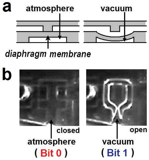
Single pneumatic valve. (a) A thin diaphragm membrane embedded on the bottom layer opens the upper channel discontinuity in the presence of vacuum in the bottom chamber. (b) Explicit visualization of valve status by the amount of light reflection. The open valve exhibits stronger reflection due to the collapsed membrane.
Fundamental building unit – pneumatic NOT gate (Inverter)
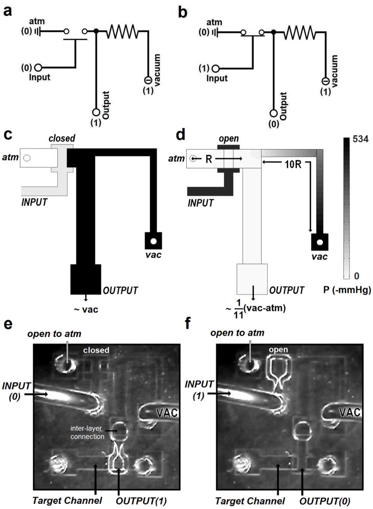
The fundamental building unit in our system is the microfluidic NOT gate (Figure 2). In our system, the NOT gate consists of a microfluidic channel (i.e. main channel) connected to vacuum source and, with an intervening valve, to an atmosphere pressure. The input to the intervening valve is the input to the NOT gate, and the output is obtained from the middle of the main channel. The electrical analogy of “power” to the gate is supplied by a vacuum source with the holes to atmospheric pressure acting as the equivalent of “ground.” The pneumatic valve is considered as an electronic on-off switch, but a ‘closed’ valve represents an ‘open’ switch (disconnection) while an ‘open’ valve corresponds to a ‘closed’ switch (connection). Note that the vacuum lines for all components can be supplied simultaneously from one large vacuum reservoir constructed in the third PDMS layer without separate individual tubing. Also, the output channel will be a dead end (e.g., a valve or a pump) even if it is an input to regulate other successive circuits.
Figure 2.
Electrical representations of the pneumatic inverter, NOT gate, are shown: (a) when the valve is closed (switch open), the main channel becomes discontinued, making vacuum-side channel a closed system. Vacuum will be transferred to the output without pressure drop. (b) when the valve is open (switch closed), the main channel becomes connected, generating pressure drop along the channel. Since most of the resistance exists at the vacuum-side, the output becomes close to atmospheric pressure. Schematics and simulated pressures in a NOT gate are shown for input signals of atmospheric pressure (c) and vacuum (d). The channel connecting the vacuum source to the output has ~10 times more flow resistance than the channel connecting the pressure source. The right panel (d) explicitly shows the pressure gradients due to this resistance, producing almost atmospheric pressure as the output. Visual observations with the asymmetric NOT gate operating on the inputs of atmosphere (e) and vacuum (f). When the input valve is closed (input signal of atmospheric pressure), the output channel goes to vacuum. When the input signal is vacuum, the input valve open and the output pressure increases to near atmosphere.
The NOT gate, by definition, will produce a signal opposite of its input signal at the output. The input signal to the NOT gate operates the normally closed microvalve. For an atmospheric pressure input (Bit 0), the valve remains closed so that the output channel is connected only to the vacuum port, generating vacuum at the output (i.e., the opposite of the input) (Figure 2a). In contrast, when a vacuum input (Bit 1) is received, the valve opens and the two pressure sources at the channel ends are connected (Figure 2b), resulting in air flowing from the atmospheric source to vacuum. The pressure drop along this flow path is governed by the resistances of the channel and, by designing the vacuum-side channel to have approximately 10 times higher resistance (i.e., narrower width; see Figures 2c and 2d) than the atmospheric side, the output channel maintains a pressure close to atmospheric pressure. This asymmetric difference in resistances is key to the function of such pneumatic NOT gates. Note that the small amount of pressure drop resulting in the output signal being slightly below atmospheric pressure never accumulates during signal transportation from one circuit to another since each circuit unit is a completely closed system and has its own fresh atmosphere and vacuum supplies.
Figures 2e and 2f show a PDMS asymmetric NOT gate connected to a valve on a target channel and operating at the two different binary pressure inputs. As long as the input pressure level is atmosphere (Bit 0), the valve in the NOT gate will remain closed and the output will remain at vacuum thus opening the valve on the target channel (Figure 2e). Applying vacuum at the input opens the valve in the NOT gate and produces atmospheric pressure at the output, thus closing the valve on the target channel (Figure 2f). Note that the opening and closing of the output valve can be visually observed, as stated before, by the change in light reflection. The operation of the valve can also be monitored by measuring the flow of gas or liquid through the target channel.
The signal strength required to operate the NOT gate depends on valve geometry. The pneumatic valve in the gate has a thin membrane shared by the upper flow channel and the bottom valve-operating chamber (Figure 3a). The membrane may stay unstressed (closed) or may be pulled toward the lower channel (open) depending on the pressure levels in the two channels. Assuming the bottom chamber resides at the center of upper channel discontinuity, for a constant membrane thickness, geometrical characteristics of each valve can be simply expressed as an area fraction as
Figure 3.
(a) Top and side views of the pneumatic valve. Shaded area represents the area fraction covered by the upper channel in the diaphragm membrane. (b) Plot of the threshold pressure levels as a function of the area fraction occupied by the upper flow channels in the valve diaphragm. Blank squares represent the minimum strength of vacuum required to open the input valve in a pneumatic inverter and solid triangles represent the minimum pressure to close the already opened input valve. (c) Output pressure variation during operation of the NOT gate depending on the input pressure. Threshold pressures to open/close the input valve are displayed in dotted lines (area fraction = 0.4).
| (1) |
This area fraction is a nontrivial design parameter and, in general, as area fraction increases, it gets more difficult (and slower) to open the closed valve but easier (and faster) to close the already-open valve.
In addition to the fractional area, there will be another parameter, the absolute minimum atmospheric pressure level that can be still considered Bit 0 (i.e., a lowest pressure below atmospheric that will make an already-open valve closed). Pressure levels below this absolute minimum will not be able to close the valves and thus cannot act as Bit 0. Likewise, there is an absolute minimum vacuum level considered Bit 1 to open a closed valve. Each of the absolute minimum levels is a function of the area fraction in Eq. (1) and determine the required pressure levels (thresholds) to open or close valves (Figure 3b).
From design perspectives, there exists a certain optimal range of the area fraction as a function of channel flow resistance for correct and sufficiently fast valve operation. In these preliminary experiments using ~100μm thick membrane, its optimal range was found from 0.3 to 0.5 when Rvac=10Ratm.
When properly designed, the change of the status responding to the input is almost instantaneous. Figure 3c shows the output pressure variation of the NOT gate as a function of the input pressure when opening and closing the input valve. As seen in Figure 3b, valve opening and closing have different threshold levels. In general, for an input valve with sufficiently large area fraction (Eq. (1)), valve opening tends to require lower pressure levels than closing. Once the input signal strength is beyond the threshold, the valve experiences almost an instant state change; there has been no observed meta-stable transitional state where a certain pressure would produce a level of neither 0 nor 1. For these NOT gates and other circuits, any channels or chambers will maintain stable pressure levels of either 0 or 1.
To build complex logic circuits, there should be no signal loss during transmission from one logic component to the next so that cascades of logic gates are possible. In other words, it is necessary that the strength of input signals should be maintained at any output ports so that the output signals can be used as inputs to sequential units. The NOT gates presented here are asymmetric with different flow resistances to vacuum and atmospheric sources. This asymmetric nature enables the resulting output signals to hold almost the same strength (typically, more than 90%) of the atmospheric pressure, a signal sufficient to operate any input valve in the successive logic gates. The atmospheric pressure (Bit 0) and vacuum pressure (Bit 1) at the output can be roughly estimated by series fluid resistances, respectively, as follows.
| (2-1) |
| (2-2) |
where Ratm and Rvac are the flow resistances for the atmosphere-side channel and the vacuum-side channel of the pneumatic inverter, respectively; Pvac is the pressure level of vacuum reservoir; and Patm is atmosphere pressure. Note that pneumatic signals in each circuit will always be boosted from one component to the next since the signals terminate in valves that have their own vacuum or atmospheric source, thus eliminating the possibility of undesirable accumulated signal loss.
Complex circuit construction using NOT, NOR, and NAND gates
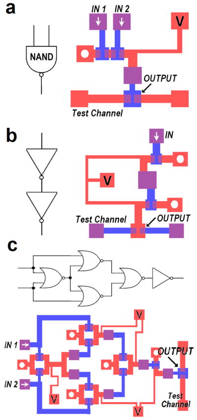
With simple additions to the asymmetric NOT gate, other logic gates can be constructed strating from the NOR gate and the NAND gate, i.e., two universal logic gates (see Figure S-2 in the electronic supplementary information for their development from a NOT gate and their electrical representations). The NOR gate is operated by two parallel input valves such that, when either one or both of the input valves open, air flows into the main channel and generates an atmospheric output signal. The output remains as vacuum only if both input valves are closed (i.e., both inputs are 0) (Figure 4). Likewise, for the NAND gate (Figure 5a and Figure S-3 in the electronic supplementary information), both of the two serial valves must be open together to produce an atmospheric output. Otherwise, vacuum will be maintained at the output.
Figure 4.
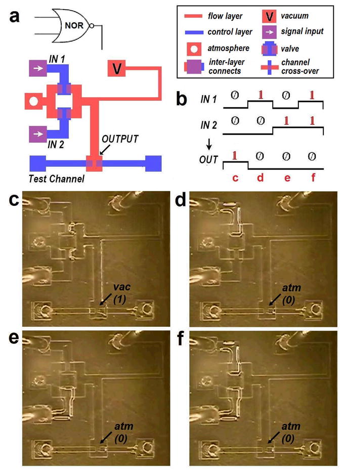
NOR gate schematic and operation. (a) CAD design of a NOR gate. In this and later figures, the bottom ‘control’ layer is shown in blue while the upper ‘flow’ layer is in red. The overlapped regions are visible in violet. Red squares with an empty circle are the holes that remain open to atmosphere during operation and those with ‘V’s indicate connections to vacuum reservoir. White arrows in the squares show the signal input locations and violet squares represent inter-layer connections between the bottom and upper layers. Channel crossovers between two layers are also shown in violet, but not as an individual square. (b) Output variations depending on two inputs. (c) NOR gate working with the 0-0 input. The output channel shows deformation or increased light reflection around the boundaries due to the existing vacuum (i.e., an output state of 1). (d) NOR gate with the 1-0 input. The upper input valve is open while the other remains closed. The output channel is now connected to atmosphere and light reflection decreases as the channel redeems the original shape. The output is obtained for (e) a NOR gate with a 0-1 input and (f) a NOR gate with a 1-1 input.
Figure 5.
Electrical representations and CAD designs of (a) a NAND gate, (b) a buffer, and (c) an XOR gate. Inter-layer connections in individual violet squares have an internal hole between the ‘control’ and ‘flow’ layers.
With these cascadable universal gates (i.e., NAND and NOR) along with the NOT gate, many other more complicated logic gates and circuits can be formed. For example, two regular NOT gates connected in series become a buffer element (Figure 5b) that helps maintain or amplify signals during the long course of signal transfer. As known from electronic gate assembly techniques, arranging four NOR gates and a NOT gate will constitute an XOR gate (Figure 5c). Some of the embedded gates share a single vacuum supply line to make the channel network simpler (see the electronic supplementary information for their operations and logic truth tables in pneumatic terms). Also, eliminating the NOT gate from the XOR circuit produces an XNOR gate (Figure S-4). Note that the response time of the XNOR gate between the input signal change and the corresponding output change was only milliseconds, resulting in no noticeable delay in signal propagation.
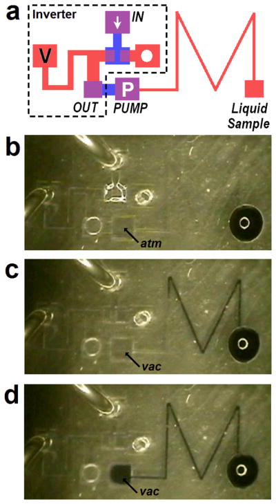
Although we have focused on logic circuits, there are obviously other uses for these structures. As an example, Figure 6 shows a pump consisting of a logic device (i.e., a NOT gate) and two chambers stacked on top of one another and separated by a thin, air-permeable PDMS membrane. When a Bit 1 (vacuum) signal is sent from the logic circuit to the bottom chamber, the pump is actuated. The deflection of the membrane downward causes a partial vacuum to form in the upper chamber and draws liquid in the upper channel towards the pump (Figure 61c). For short actuation times, this motion is completely reversible. For long times, air can flow through the membrane and it decreases the pressure in the upper chamber. As a result, the fluid will be drawn through the channel (Fig. 6d). Such micropneumatic pump can be also used to vent unwanted air gaps from dead-end channels, eliminate air bubbles in the liquid samples, and route fluid flow in the complex networks (20).
Figure 6.
Membranous pneumatic pump operations. (a) CAD design of a pneumatic pump. The pneumatic pump is shown in the violet square with the white ‘P’ to discern it from an inter-layer connect. The pump status is based on the output from the prior circuit (a pneumatic inverter in this example) within the dotted boundaries. (b) At the inverter input of 1, its output becomes 0 and the pump is at rest. (c) At the inverter input of 0, its output becomes 1 and the pump turns on. The membrane in the pump chamber deflects and draws fluid towards it. (d) With continued applied vacuum, the air passes through the pump membrane and the fluid motion continues until the chamber gets filled with the liquid.
Pneumatic Flip-flops
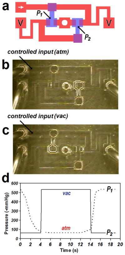
As shown in Table 1, the pneumatic logic gates in the previous sections comprise the building blocks for more advanced pneumatic circuits. One crucial component necessary for serial data processing is the flip-flop. A bistable pneumatic flip-flop has been built by employing two regular NOT gates with each output fed back to the other input (Figure 7). For the two input valves, only one valve can be open at a time – the other must be closed. Once either valve is set, both valves maintain their opposite statuses infinitely, remaining ‘latched.’ Such bistable flip-flops can be an essential element of microfluidic memory devices, which memorize valve operational commands for current or later use. Note that the flip-flop change states when the level of externally controlled pressure (P1) exceeds the threshold defined for individual valves of the NOT gates. The pressure level of the other valve (P2) changes essentially instantaneously to the opposite value.
Table 1.
Pneumatic circuit operators and their symbols.
| Operators | Symbols | Building Combinations | Functions |
|---|---|---|---|
| Inverter (NOT) |  |
basic building block | outputs 0 (1) if the input is 1 (0). |
| NOR |  |
basic building block | outputs 1 only if both inputs are 0. |
| NAND |  |
basic building block | outputs 0 only if both inputs are 1. |
| Buffer |  |
maintains the input. | |
| OR |  |
outputs 0 only if both inputs are 0. | |
| AND |  |
outputs 1 only if both inputs are 1. | |
| XNOR |  |
 |
outputs 0 only if two inputs differ. |
| XOR |  |
 |
outputs 1 only if two inputs differ. |
| Bistable Flip-flop |  |
 |
maintains the input (S) even after the signal disappears. |
| D Latch (gated) |  |
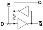 |
accepts the input (D) when the gate (E) opens and maintains the output after closed. |
| Edge Detector |  |
outputs 1 whenever detecting rising edges in the input. | |
| Toggle |  |
 |
toggles the output when the input (T) is 1. |
| Clock Generator (Oscillator) |  |
 |
generates clock pulses. |
| D Flip-flop (clocked) |  |
 |
shifts the input bit by one clock cycle. |
| Shift Register | n/a | shifts multiple bits by one clock cycle. |
Figure 7.
Operation of a pneumatic bistable flip-flop. (a) CAD design of a flip-flop. The pressure levels of P1 and P2 are indicators for the flip-flop’s states. (b) When input at P1 of 0 is forcedly supplied, the input-side valve closes and the other valve instantly opens. (c) When the input of 1 is forcedly supplied, the input-side (left) valve opens and the other (right) valve instantly closes. (d) Plot of pressure level changes. P1 (control) and P2 (response) are always opposite to each other and change only by external perturbations. When the controlled pressure level (P1) exceeds thresholds for the valve, instantaneous pressure changes in response (P2) are observed.
Interestingly, such PDMS flip-flops can be manually operated by pressing on the open valve. Due to the elasticity of PDMS, any open PDMS valve can be forced into the closed state by pressing on the top surface, even if the valve bottom chamber is under vacuum. For a single valve, the valve will return to its previous ‘open’ status immediately after the operator stops the mechanical force. However, for these flip-flop structures, once one valve is forced closed, the other valve instantly opens and the whole structure maintain its new status even after the mechanical force is removed. Another mechanical ‘touch’ to close the newly opened valve will in turn make the original valve open again. Since pneumatic signals in these flip-flops can be transferred to any other circuits or target valves/pumps, this ‘touch microfluidic control’ would make possible complex operations of multiple active microfluidic components without any computerized control elements, electrical power, solenoid valves, or complicated tubing.
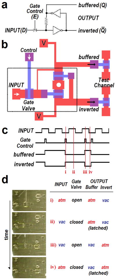
Pneumatic circuit components that have latching capability are indispensable for the development of a large scale integrated microfluidic system that can address hundreds of individual valves independently. The gated D latch circuit, which produces two opposite ‘latchable’ outputs (buffered and inverted), has been constructed from a bistable pneumatic flip-flop and a gate control valve (Figure 8). When the gate valve is open, the input signal can change the state of the flip-flop or, if the pre-existing signal matches the external input, leave the state of the flip-flop unchanged. The feedback route to the input side of the flip-flop has a high flow resistance – narrow/long channel – in order to avoid crosstalk between the new input signal and the previous flip-flop feedback signal. When the gate valve is closed, the circuit returns to a regular bistable flip-flop and maintains the signals at both output ports infinitely; the buffered output produces the same binary pressure level as the input while the inverted output holds the opposite level. While previously reported pneumatic latching valves can retain the signal only for minutes (18), the outputs from our latch circuits persist infinitely without any loss of signal strength.
Figure 8.
Pneumatic gated D latch with buffered and inverted output ports. (a) Electrical representation of the D latch. (b) CAD design. (c) Output variations depending on the input signal and the status of the latch valve. The latch valve opens when its control signal is vacuum (1). (d) Sequential operations of a latching circuit. Photos are taken for the area of the dotted frame in Figure 13b.
We have also developed a positive edge detector, an essential component for constructing more complex flip-flops (see Figure S-6 in the electronic supplementary information for their composition and operations). The edge detector produces short Bit 1 signals whenever a pneumatic input signal changes from Bit 0 to Bit 1. The device makes use of the difference in signal transportation time: one input to a NOR gate is fed directly from an inverter while the second goes through an additional, intervening inverter. So, for a transition from atmospheric to vacuum (Bit 0 to Bit 1), the NOR gate is fed momentarily with two atmospheric or “false” signals (the fast inverted new signal and the slower double-inverted old signal) that in turn produce a “true” signal (Bit 1) at the NOR output for a short time (<200ms). As soon as the later signal reaches the NOR gate, the output loses its temporary “true” signal and returns to a “false” state.
A clock doubler or toggle can be developed from such an edge detector by adding a bistable flip-flop (see Figure S-7 in the electronic supplementary information for their construction and operations). The output from the positive edge detector operates a valve on a feedback line from the output. When the edge detector goes “true,” the signal perturbs the flip-flop with an external feedback that is always, by definition, opposite of its current state. Thus every change in signal from Bit 0 to Bit 1 will flip the output signal of the toggle while every transition from Bit 1 to Bit 0 will have no effect. This unique flipping capability is essentially a clock cycle doubler that takes clock pulses with a certain cycle as the input and produces the clock pulses with a doubled cycle or a halved frequency. A basic pulse counter can also be constructed with multiple toggles in series (data not shown).
Serial to parallel data conversion for microfluidic control operations
Serial or sequential data is composed of a string of binary bits that are distinguishable temporally. Clock signals provide temporal placeholders for serial data where one clock cycle represents the smallest time that can carry a bit of information. The pneumatic clock signal consists of pulses oscillating at a certain frequency between atmospheric and vacuum pressure levels. Therefore, to process serial data, a clock signal (01010101…) must be present in addition to the data signal (e.g., 00101110…). Although the clock pulses may be provided as a separate input, they can be also generated within the pneumatic circuit by employing a pneumatic clock generator. The clock generator consists of a NOT gate that uses its own output connected to its input through a resistance and capacitance in series (Figure S-8). The resistance is a narrow, long channel while the capacitor is an upper chamber in the ‘flow’ layer above a bottom chamber in the ‘control’ layer separated by a deflectable membrane. Once the vacuum reservoir is connected to the clock generator, the circuit immediately starts generating clock pulses at a fixed frequency. The clock frequency can be altered by changing the resistance and capacity of the channel, i.e., the channel length, width, or the capacitor chamber size.
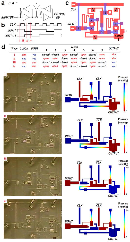
A shift register, critical for serial data processing, can decode the information contained in multiple sequential bits. In specific, a shift register takes in a new bit of binary data for each clock cycle, shifting the existing old bit to successive outputs. By spatially separating temporal signals, shift registers can, essentially, parallelize serial information. Figure 9 illustrates the pneumatic clocked D flip-flop that constitutes a micropneumatic shift register (MSR). A clocked D Flip-flop consists of two consecutive D latches with a regular clock pulse supplied to the gate valve of the first D latch and an inverted clock pulse supplied to the gate valve of the second. The bit shifting in the D flip-flop occurs through two sequential steps for one clock cycle. As the clock signal goes to Bit 1, the first gate valve opens to transfer the data signal to the first D latch. As the clock signal goes to Bit 0, the first gate valve closes to prevent data changes from entering the system and the second gate valve opens to move the data signal from the first D latch to the second D latch. Thus, for each clock cycle, the data moves from the input to the output of the D flip-flop.
Figure 9.
Pneumatic D flip-flop (clocked) (a) Electrical representation. (b) Output variations depending on the clock cycles and the command input. A series of bits from the input are shifted along every clock cycle. (c) CAD design. Embedded pneumatic valves in operation are numbered respectively for references. (d) Sequential operations of the MSR. The pneumatic signals and corresponding valve statuses are listed for each stage (i to iv) to analyze how the signals propagate. The analysis was confirmed experimentally (left column) and by simulations (right column).
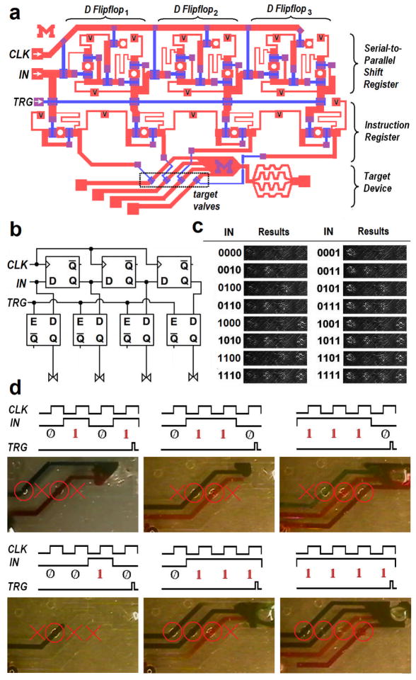
Serial-to-parallel micropneumatic shift registers (MSRs) are built by connecting multiple D flip-flops in series. With n D flip-flops, n+1 bits of sequentially encoded data are available at the parallel outputs of the MSR after n clock cycles (the (n+1)th bit is obtained from the original input data before it enters the first D flip-flop). Figure 10 shows a 4-bit digital pneumatic processor capable of converting serial input data (4-bit commands) to independently control target valves on four microfluidic channels. The processor is comprised of an MSR with three clocked D flip-flops to spatially separate the serial information, four gated D latches (i.e., instruction register) to “memorize” the instructions, and four triggering valves to determine when the input serial command will be transferred to the four microfluidic channels. Note that a particular command set (i.e., the state of the four valves encoded in four serial data pulses) will persist until a new command set is transferred to the D latches by the triggering valves.
Figure 10.
4-bit digital pneumatic microprocessor. (a) CAD design of the 4-bit processor consisting of a 3-bit MSR with three D flip-flops and a 4-bit instruction register that controls the target mixing device with four independent valves. Serially encoded input commands are shifted by accompanying clock pulses, generating four independent parallel outputs to control the corresponding command valves in the fluidic channels. (b) Electrical symbolic representation. (c) Statuses of four target command valves depending on the input commands. (d) Various command sequences were supplied to perform different mixing tasks. Note that the maintained outputs keep some valves open and the others closed during mixing operations.
In the exemplary application, four different color dyes were selectively controlled for mixing using various command sequences. The 4-bit commands from the pneumatic processor will determine which valve is open and, thus, which of the four dyes will be mixed in the fluid chamber. Note that the command bits from the instruction register are delivered in the ‘control’ layer and the delivery channels cross over the flow channels in the ‘flow’ layer. Such crossovers may cause minor signal interference if the separating PDMS membrane is too thin (≪100um). The signal interference can be obviated by decreasing the crossover area, increasing the membrane thickness, or adding a third layer for fluidic crossovers. Using air-impermeable material for the separating layer instead of PDMS will also prevent any possible signal interference.
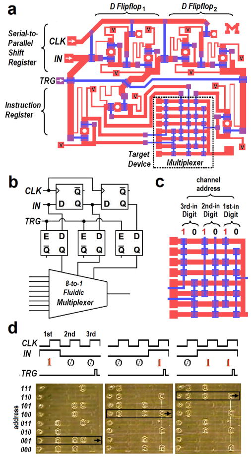
Such individually accessible command valves can be also used in multiplexing systems and, by using n D flip-flops in a serial-to-parallel MSR, 2(n+1) flow channels can be individually addressed. For example, Figure 11 shows 8 different flow channels are selectively accessed by the 3-bit address decoder and multiplexer. Each flow channel has three different valves along its length with each one controlled by one bit of the decoder. All three valves must be open for fluid to flow in a channel. Note that, for each bit, half of the valves open when the corresponding bit is true but the other half open when false. A tree combination of binary valves completes such multiplexing channels and each channel will be endowed with its own address (Figure 11c). For instance, when a 3-bit address of “111” is summoned, only the uppermost channel will be open (its three valves are all open) and connected to the outlet. Likewise, a “000” address command will open the bottom channel while keeping other channels closed.
Figure 11.
3-bit digital pneumatic microprocessor. (a) CAD design of the 3-bit processor consisting of a 2-bit MSR with two D flip-flops and a 3-bit instruction register that controls the valve network in the target multiplexer. It generates three independent parallel outputs from serial address input to multiplex eight individual channels. (b) Electrical symbolic representation. (c) Each of the eight channels has its own address. Half of the valves open at 1 while the other half open at 0. (d) Various address sequences were provided to select specific channels. Fluid samples can flow along the channel when all of its three valves are open.
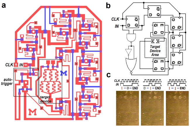
By adding combinatorial circuits, more complex computing capabilities can be realized in digital pneumatic processors with fewer inputs. For instance, instead of using a separate trigger signal to initiate signal transfer from shift registers to instruction registers, the triggering can be automated by encrypting a command termination code (‘END’) in the original serial input data. The processor in Figure 12 was devised to take one command bit every two clock cycles (intervening bits would always be “false”) and recognize the termination code of two consecutive “true” bits. To detect the termination code, a pneumatic AND gate (a NAND gate followed by a NOT gate) was used. A positive edge detector finds the true signal from the AND gate output and automatically produces a short triggering signal. Since additional commands can be sent and transferred after each termination code, the device can work as a multipurpose programmable microfluidic platform. Note that employment of a pneumatic clock pulse generator will further simplify the processor platform by eliminating the need for external solenoid clocking (Figure S-9).
Figure 12.
2-bit digital pneumatic microprocessor with autonomous triggers (a) CAD design of the 2-bit processor consisting of the 5-bit MSR with five D flip-flops and the 2-bit instruction register that individually controls the two valves in the target device. It produces two independent parallel outputs from serially encoded input command with the embedded auto-triggering code in order to control the inlet valves in the molecular gradient-generating device. (b) Electrical symbolic representation. (c) Depending on the input commands, the two valves were independently controlled.
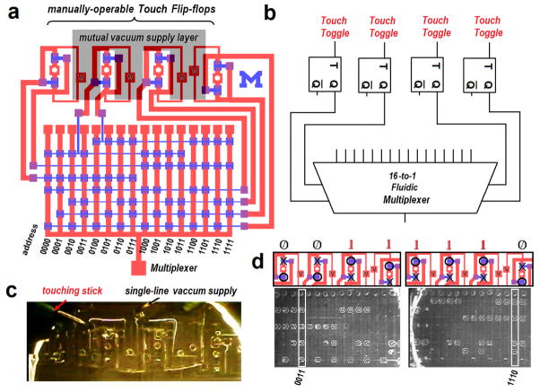
In addition to control by serial pneumatic signals, the manually-operated flip-flops, or ‘touch’ flip-flops, can allow direct user control of the devices. ‘Touch’ flip-flops can be built on the same plane with any target device by multilayer soft-lithography. Figure 13 shows four manually operable flip-flops used to control sixteen (24) channels. Each flip-flop can have two different statuses, one at a time, and thus represents one command bit. Given that each command bit can actuate one active component such as a valve or a pump, the number of required flip-flops will be as many as that of active components that need to be independently controlled. A 4-bit command, entered by manually touching the flip-flops, will thus correspond to a particular address of the channel that will open while the others keep closed. Such ‘touch microfluidic control’ may provide the simplest and easiest control of active components for microfluidic devices because it operates without the need for external dedicated control lines, computerized pressure control, or electrical power. In addition, different from portable screw-based valves (21–22), the fabrication of ‘touch control’ systems is straightforward and the change of valve status is instant. Note that, since the volume of air processed in the changing of states is relatively small, the vacuum source necessary for operation can easily be accomplished using a handpump.
Figure 13.
Touch Microfluidic Control. (a) CAD design of a manually operable multiplexer by four ‘touch’ flip-flops that generates independent outputs to address sixteen channels by multiplexing. For the entire platform, vacuum must be supplied to four different ports. Black dashed boundaries indicate the third ‘supply’ layer where vacuum is distributed from one line to all ports simultaneously without separate tubing. (b) Electrical symbolic representation. (c) Photo of the PDMS ‘supply’ layer on the top of the device. The vacuum supply layer covers all of the four vacuum ports (‘V’s) and a single line of vacuum is supplied to the layer in order to power up the entire device. (d) Various addresses can be accessed by touching one or more valves in the touch flip-flops. Fluid samples can flow along the channel with all of its four valves open.
Conclusions
The miniaturization and on-chip integration of control elements in microfluidic systems has the potential to reduce the complexity of interconnections and auxiliary equipment. Regardless of the number of valves or pumps to control, the proposed digital pneumatic microprocessors can operate with only one serially encoded control line for pneumatic commands and one line for power (i.e., vacuum) input; clock pulses and triggering signals can be either provided as separate inputs or automatically generated using additional logic circuits on the same device. Also, there is no theoretical limit to the number of target parallel outputs although physical limitations will certainly exist.
One challenge, like in the computer industry, is to devise practical methods for scaling down pneumatic valves and corresponding control components. By standard soft-lithography, we have built small D latches occupying only ~35mm2. Considering that a clocked D flip-flop with associated channel networks takes up 3–4 times more area than a D latch, it is plausible to build >50 D flip-flops in a 10 cm diameter wafer-size device. Since n D flip-flops are capable of producing n+1 independent pneumatic controls, a wafer-size pneumatic microprocessor as a control platform will govern more than 50 parallel outputs individually. Employing a multiplexing scheme (7), over a quadrillion (1015) individual channels or chambers can be controlled from only a single input control line. We were also able to construct a working gated D latch circuit at one-fourth the size without any change in design suggesting that larger decreases in size are possible although optimized design most likely will be necessary.
Another improvement to be pursued includes operational speed (i.e., clock frequency). The pneumatic microprocessors described here have operated at relatively low clock speed (<0.5 Hz). At this clock speed, it takes more than 30 seconds to decode each 16-bit command. However, smaller valves should be able to operate more quickly due to shorter interconnect distances and faster membrane response times. Constructing components that operate between a pressure source (rather than atmosphere) and vacuum may also increase the maximum cycling rate since greater pressure differences can be obtained. However, in terms of computational power, such pneumatic microprocessors cannot compete with their electronic counterparts but they offer an additional control axis (i.e., mechanical vs. electrical) as well as the potential for increased speed.
Operations of the presented pneumatic microprocessors rely on the driving force of pressure difference between vacuum and atmosphere. A sufficiently strong vacuum can be obtained by a simple hand pump or an aspirator constructed from running water. Use of electrically-powered solenoid valves is also optional when generating pneumatic commands or clock pulses. Simple manual operation with appropriate vacuum supply tubing may replace the solenoid switching (See the electronic supplementary information). Such non-electrical operations make possible the use of these pneumatic microprocessors where the conventional laboratory environment is not available. Consequently, the pneumatic logic circuits and microprocessors may be particularly useful for use in remote locations as well.
Supplementary Material
Acknowledgments
This work was partially funded from the National Institute of Health (5-P01-HG001984, R01-AI049541, R01-GM-37006-17).
References
- 1.Pal R, Yang M, Lin R, Johnson BN, Srivastava N, Razzacki SZ, Chomistek KJ, Heldsinger DC, Haque RM, Ugaz VM, Thwar PK, Chen Z, Alfano K, Yim MB, Krishnan M, Fuller AO, Larson RG, Burke DT, Burns MA. Lab chip. 2005;5:1024–1032. doi: 10.1039/b505994a. [DOI] [PubMed] [Google Scholar]
- 2.Burns MA, Johnson BN, Brahmasandra SN, Handique K, Webster JR, Krishnan M, Sammarco TS, Man FP, Jones D, Heldsinger D, Namasivayam V, Mastrangelo CH, Burke DT. Science. 1998;282:484–487. doi: 10.1126/science.282.5388.484. [DOI] [PubMed] [Google Scholar]
- 3.Hong JW, Quake SR. Nat Biotechnol. 2003;21:1179–1183. doi: 10.1038/nbt871. [DOI] [PubMed] [Google Scholar]
- 4.Rhee M, Burns MA. Lab Chip. 2008;8:1365–1373. doi: 10.1039/b805137b. [DOI] [PubMed] [Google Scholar]
- 5.Unger MA, Chou H-P, Thorsen T, Scherer A, Quake SR. Science. 2000;288:113–116. doi: 10.1126/science.288.5463.113. [DOI] [PubMed] [Google Scholar]
- 6.Lagally ET, Scherer JR, Blazej RG, Toriello NM, Diep BA, Ramchandani M, Sensabaugh GF, Riley LW, Mathies RA. Anal Chem. 2004;76:3162–3170. doi: 10.1021/ac035310p. [DOI] [PubMed] [Google Scholar]
- 7.Thorsen T, Maerkl SJ, Quake SR. Science. 2002;298:580–584. doi: 10.1126/science.1076996. [DOI] [PubMed] [Google Scholar]
- 8.Grover WH, Skelley AM, Liu CN, Lagally ET, Mathies RA. Sens Actuators B, Chem. 2003;89:315–323. [Google Scholar]
- 9.Grover WH, Mathies RA. J Micromech Microeng. 2007;16:1378–1385. [Google Scholar]
- 10.Belsterling CA. Fluidic Systems Design. Wiley-Interscience; New York: 1971. [Google Scholar]
- 11.Foster K, Parker GA. Fluidics: Components and Circuits. Wiley-Interscience; New York: 1970. [Google Scholar]
- 12.Groisman A, Enzelberger M, Quake SR. Science. 2003;300:955–958. doi: 10.1126/science.1083694. [DOI] [PubMed] [Google Scholar]
- 13.Cheow LF, Yobas L, Kwong D-L. Appl Phys Lett. 2007;90:054107. [Google Scholar]
- 14.Prakash M, Gershenfeld N. Science. 2007;315:832–835. doi: 10.1126/science.1136907. [DOI] [PubMed] [Google Scholar]
- 15.Vestad T, Marr DWM, Munakata T. Appl Phys Lett. 2004;84:5074–5075. [Google Scholar]
- 16.Toepke MW, Abhyankar VV, Beebe DJ. Lab Chip. 2007;7:1449–1453. doi: 10.1039/b708764k. [DOI] [PubMed] [Google Scholar]
- 17.Zhan W, Crooks RM. J Am Chem Soc. 2003;125:9934–9935. doi: 10.1021/ja0366585. [DOI] [PubMed] [Google Scholar]
- 18.Grover WH, Ivester RHC, Jensen EC, Mathies RA. Lab Chip. 2006;6:623–631. doi: 10.1039/b518362f. [DOI] [PubMed] [Google Scholar]
- 19.Xia YN, Whitesides GM. Annu Rev Mater Sci. 1998;28:153–184. [Google Scholar]
- 20.Rhee M, Burns MA. Sens Transducers. 2008;3:37–46. [Google Scholar]
- 21.Zheng Y, Dai W, Wu H. Lab Chip. 2009;9:469–472. doi: 10.1039/b811526e. [DOI] [PubMed] [Google Scholar]
- 22.Weibel DB, Kruithof M, Potenta S, Sia SK, Lee A, Whitesides GM. Anal Chem. 2005;77:4726–4733. doi: 10.1021/ac048303p. [DOI] [PubMed] [Google Scholar]
Associated Data
This section collects any data citations, data availability statements, or supplementary materials included in this article.


