Abstract
Purpose: An optimal material selection for primary modulator is proposed in order to minimize beam hardening of the modulator in x-ray cone-beam computed tomography (CBCT). Recently, a measurement-based scatter correction method using primary modulation has been developed and experimentally verified. In the practical implementation, beam hardening of the modulator blocker is a limiting factor because it causes inconsistency in the primary signal and therefore degrades the accuracy of scatter correction.
Methods: This inconsistency can be purposely assigned to the effective transmission factor of the modulator whose variation as a function of object filtration represents the magnitude of beam hardening of the modulator. In this work, the authors show that the variation reaches a minimum when the K-edge of the modulator material is near the mean energy of the system spectrum. Accordingly, an optimal material selection can be carried out in three steps. First, estimate and evaluate the polychromatic spectrum for a given x-ray system including both source and detector; second, calculate the mean energy of the spectrum and decide the candidate materials whose K-edge energies are near the mean energy; third, select the optimal material from the candidates after considering both the magnitude of beam hardening and the physical and chemical properties.
Results: A tabletop x-ray CBCT system operated at 120 kVp is used to validate the material selection method in both simulations and experiments, from which the optimal material for this x-ray system is then chosen. With the transmission factor initially being 0.905 and 0.818, simulations show that erbium provides the least amount of variation as a function of object filtrations (maximum variations are 2.2% and 4.3%, respectively, only one-third of that for copper). With different combinations of aluminum and copper filtrations (simulating a range of object thicknesses), measured overall variations are 2.5%, 1.0%, and 8.6% for 25.4 μm of copper, erbium, and tungsten, respectively. With and without 300 μm of copper in the beam, the measured variations for 25.4 μm of copper, erbium, and tungsten, 1 mm of aluminum, as well as 406 μm of copper, are 1.8%, 0.2%, 5.5%, 1.9%, and 7.5%, respectively.
Conclusions: The spatial variation in the effective transmission factor of the modulator blocker due to beam hardening caused by the modulator itself reaches a minimum when the K-edge of the modulator material is near the mean energy of the spectrum. An optimal modulator material selection using the K-edge discontinuity is therefore proposed.
Keywords: primary modulator, K-edge, beam hardening, scatter correction
INTRODUCTION
Scatter is a critical issue that impacts image quality in x-ray cone-beam computed tomography (CBCT), and scatter correction is an active and challenging topic of research. A promising scatter correction method using primary modulation was recently proposed and verified.1, 2, 3 By inserting a primary modulator between the source and the object, part of the primary is modulated to high frequency while scatter still has dominant low-frequency components, making the modulated primary and the scatter highly separable in the frequency domain. After demodulation, scaling, and subtraction, a scatter distribution can be estimated and removed. This estimate is acquired using one single scan, without loss of real-time imaging capabilities and with no increase in patient dose.
The primary modulator consists of attenuating blockers arranged in a high-spatial-frequency pattern. The performance of the primary modulation method depends on the system parameters of the primary modulator and primarily on the spatial frequency of the blocker and the transmission factor of the blocker itself. Optimization of the primary modulator design is important. The characteristic dimensions of the blocker pattern should be as small as possible in order to achieve a high modulation frequency. The transmission factor of the modulator blocker, which determines the modulation function, should be neither too high nor too low in order to achieve sufficient signal modulation without too much reduction of patient entrance x-ray fluence. The value of the transmission factor is required to be spatially uniform so that a uniform modulation function is created. Moreover, the insertion of the primary modulator should not cause inconsistency in the primary signal; the primary measured with both the modulator and the object in the field of view (FOV) should be equal to the product of the primary measured with only the object in the FOV and the modulation function measured with only the modulator in the FOV. Unfortunately, for a polychromatic x-ray system, such an inconsistency always exists due to beam hardening caused by the modulator itself. The impact of this inconsistency on the performance of scatter correction can be evaluated by assigning all of the beam hardening effect in the system to the modulator, and then evaluating the magnitude of the inconsistency as a function of object size and composition. The presence of a nonuniform object causes the modulation function to be spatially nonuniform even though its initial value (measured without an object in the FOV) is uniform. The nonuniformity of the modulation function results in errors in scatter estimation and artifacts in reconstructed images.
It is well-known that beam hardening is also a challenging issue for CT reconstruction. Numerous methods have been proposed and implemented using preprocessing algorithms,4, 5 postprocessing algorithms,6, 7 and dual-energy techniques.8 For the primary modulation method, as stated above, the beam hardening caused by the modulator leads to an inconsistency in the primary signal and eventually to a spatially varying transmission factor. This effect cannot be easily corrected using traditional beam hardening correction methods because of the contamination of scatter. Our first approach is therefore to minimize beam hardening of the modulator by selecting an optimal material.
Generally, low atomic number (Z) materials, such as beryllium, generate less beam hardening than high Z materials, such as copper, for the same value of transmission factor. Because of the penumbra effect and geometric magnification, the blockers in the modulator should be thin enough so that the blocker size can be small. Thus, beryllium and aluminum are out of consideration if a low transmission factor is required. A common perception when selecting the modulator material is that lower Z is necessarily better as long as the corresponding blocker thickness is appropriate. In fact, a higher Z material, whose K-edge energy is near the mean energy of the x-ray system spectrum, may generate less beam hardening than a lower Z material.
The K-edge effect causes a sudden increase in the mass attenuation coefficient when the photon energy is above the binding energy of the K-shell electrons, which breaks the trend of mass attenuation coefficient decreasing as the photon energy (<200 keV) increases.9 Section 3B shows a graph of mass attenuation coefficient plotted as a function of energy, illustrating this effect. This effect has been utilized in mammography and x-ray absorptiometry, where K-edge filters are designed to optimize the x-ray spectrum.10, 11, 12, 13 In our primary modulation method, we show that when the K-edge energy of the modulator material (specifically the blocker material) is near the mean energy of the x-ray spectrum, the K-edge discontinuity in the curve of the mass attenuation coefficient may reduce the impact of beam hardening of the modulator. Therefore, by taking advantage of the K-edge discontinuity, an optimal material selection for a given x-ray system can be realized in three steps. First, estimate and evaluate the polychromatic spectrum for a given x-ray system including both source and detector; second, calculate the mean energy of the spectrum and choose the candidate materials whose K-edge energies are near the mean energy; third, select the optimal material from the candidates after considering both the magnitude of beam hardening and the physical and chemical properties.
This paper is organized as follows. Section 2 describes the primary modulation method and the inconsistency in the primary signal caused by the beam hardening of the modulator. Section 3 presents our material selection approach, where the fact that a higher Z does not always lead to increased beam hardening is shown and theoretically explained. In Sec. 4, we use a tabletop CBCT system operated at 120 kVp as an example to validate our method, from which the optimal material of the primary modulator is selected. Finally, we summarize this paper in Sec. 4 with a brief discussion.
BEAM HARDENING EFFECT IN THE PRIMARY MODULATION METHOD
Principle of the primary modulation method
The primary modulation method assumes that an ideal (spatially invariant) modulation function
| (1) |
is created by the primary modulator.1 Here, α∊(0,1) is the transmission factor of the modulator blocker and parameters i and j are the horizontal and vertical indices. With such a primary modulator in the FOV, the measured x-ray image in the spatial domain is
| (2) |
where p and s indicate primary and scatter, respectively. Taking the Fourier transform of Eq. 2, we have
| (3) |
where P and S denote the Fourier transforms of primary and scatter, respectively, and ω∊[−π,π]×[−π,π] is the 2-D coordinate of (ωx,ωy) in the Fourier domain.
From Eq. 3, we can see that part of the primary is modulated to high frequencies by the modulator and is strongly separated from the scatter, which is predominantly low frequency. Using filtering techniques, a scatter distribution can be estimated as
| (4) |
where H(ω) is a low-pass filter with a bandwidth of ωmax. Details of the scatter estimation can be found in Refs. 1, 3.
Impact of a variation in α
The accuracy of scatter estimation from Eq. 4 is highly dependent on the uniformity and the accuracy of α. Let dα be a variation in α caused by nonideal factors in the modulator design and implementation. The resulting variation in the estimated scatter would be
| (5) |
Here, we take the estimated scatter Sest(ω) as a function of α. Shifting the frequency spectrum of P′(ω) in Eq. 3 by π to get P′(ω−π), substituting it into Eq. 5, and ignoring the high frequencies of primary and scatter, one obtains
| (6) |
Therefore, it is seen from Eq. 6 that a low-frequency primary with a weighting factor of αdα∕(1−α) could be included in the estimated scatter when variation dα in α occurs. In other words, 1% of variation in the case of α=0.9 adds 9% of the low-frequency primary to the estimated scatter.
Beam hardening of the modulator
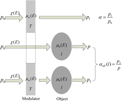
For a polychromatic x-ray system, the inserted primary modulator causes beam hardening. Let χ(E) be the spectrum of the system including the x-ray tube and the detector. As depicted in Fig. 1, the intensities of the primary before and after passing through the modulator blocker alone are
| (7) |
where C is a constant determined by the x-ray fluence and the gain of the detector, and μm(E) and T indicate the linear attenuation coefficient and the thickness of the modulator blocker, respectively.
Figure 1.
The effective transmission factor of the modulator blocker αeff in the polychromatic x-ray system with an object in the FOV. p0, p1, p, and p2 are the initial intensity of the primary, and the intensities after passing through the modulator blocker alone, the object alone, and both the modulator blocker and the object, respectively; χ(E) is the initial system spectrum including both the source and the detector; the linear attenuation coefficients and thicknesses of the modulator blocker and the object are denoted as μm, μo, T, and l, respectively. Parameter αeff can be considered as a function of the object thickness if we assume that μm, μo, and T are fixed.
Therefore, the transmission factor of the modulator blocker α is written as
| (8) |
The intensity of the primary after passing through the object alone is
| (9) |
where μo(E) and l indicate the linear attenuation coefficient and the thickness of the object, respectively. Note that primary p in both Eqs. 2, 9 refers to the same signal from which a CT image is reconstructed. The intensity of the primary after passing through both the modulator and the object is
| (10) |
We can see that, in general, the primary with both the modulator and the object in the FOV p2, in Eq. 10, does not equal the product of the primary with only the object in the FOV p, in Eq. 9, and the transmission factor of the modulator blocker α, in Eq. 8, i.e.,
| (11) |
This inconsistency in the primary signal is due to the fact that both the modulator and the object cause beam hardening, i.e., the inserted modulator hardens the effective spectrum incident on the object, or equivalently, the inserted object hardens the effective spectrum incident on the modulator. It would be avoided if either the modulator or the object had an energy independent attenuation coefficient. However, here we blame only the modulator for its beam hardening effect since it is an add-on to the conventional CT system.
The primary with both the modulator and the object in the FOV p2 can be decomposed into two parts as
| (12) |
where
| (13) |
is the effective transmission factor of the modulator blocker, with χ′(E)=χ(E)exp[−μo(E)l] being the effective spectrum for the modulator after object filtration (the object is treated as a special filter that hardens the spectrum). In Eq. 13, it is assumed that μm, μo, and T are fixed, making the effective transmission factor αeff a function of the object thickness l. Generally, only αeff(0)≡α is measured in the system calibration procedure where no object is placed in the FOV.
After decomposition, the inconsistency in the primary signal due to beam hardening caused by the modulator is purposely assigned to αeff, leading to a spatially nonuniform modulation function when an object is placed in the FOV even though a uniform modulation function is initially designed. The variation in αeff as a function of object filtration represents the magnitude of beam hardening of the modulator. It could generate considerable errors in scatter estimation as stated in Sec. 2B. Therefore, the beam hardening caused by the modulator is an important aspect to be considered in modulator design.
MATERIAL SELECTION IN MODULATOR DESIGN
Requirements for the modulator material
The material used in the primary modulator (specifically the attenuating blockers) should have good physical and chemical properties, such as being solid, stable, and easy to manufacture. Metals are therefore our major candidates. In addition, two particular requirements are necessary for a good modulator material: (1) High density or high mass attenuation coefficient and (2) weak beam hardening effect.
The first requirement is to guarantee that the blocker can be thin. To obtain an accurate scatter estimation, the modulation frequency of the primary modulator should be set as high as possible, requiring the size of the blocker to be as small as possible. As mentioned in Sec. 1, the penumbra effect of the blocker limits its minimum size for a given transmission factor. Therefore, a thin blocker is essential for the primary modulation method.
The second requirement is to reduce the spatial variation in the effective transmission factor αeff, caused by the beam hardening of the modulator as described in Sec. 2C. Unfortunately, the two requirements are difficult to satisfy simultaneously because a material with high density or high mass attenuation coefficient usually has a high Z, which results in significant beam hardening.
Minimum variation in the effective transmission factor
In the primary modulation method, what is of most concern is not the effective transmission factor αeff itself but its spatial variation over the FOV with the scanned object in place (i.e., the object filtration). According to the analysis in Sec. 2B, to obtain an accurate scatter correction, a minimum spatial variation is desired, i.e., the first order differential of αeff(l)
| (14) |
should approach zero.
Let Eeff1(l) and Eeff2(l) be the effective energies at an object thickness l, defined as
| (15a) |
| (15b) |
Then, one way to get the first order differential of αeff(l) in Eq. 14 to approach zero is to have
| (16) |
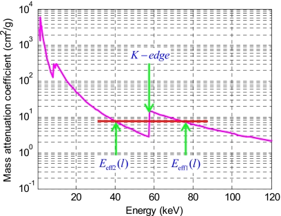
The spectrum χ′(E) in Eq. 15a is harder than the spectrum μo(E)χ′(E) in Eq. 15b. The effective energies Eeff1(l) and Eeff2(l) are related to the x-ray spectrum, the modulator, and the object. In most cases, the corresponding effective energy of the former is higher than that of the latter, namely, Eeff1(l)>Eeff2(l)⇒μm(Eeff1(l))<μm(Eeff2(l)), resulting in violation of formula 16. However, if the effective energies Eeff2(l) and Eeff1(l) are located just before and after the K-edge energy of the modulator material (as shown in Fig. 2), formula 16 may be satisfied. As both Eeff2(l) and Eeff1(l) move toward higher energies as the object thickness l increases, the particular situation (μm(Eeff1(l))=μm(Eeff2(l))) depicted in Fig. 2 may only occur at a specific l. But the first order differential of αeff(l) may still be small over a certain range of l.
Figure 2.
A situation where the first order differential of αeff(l) equals zero. The effective energies Eeff2(l) and Eeff1(l) are located before and after the K-edge energy of the modulator material. Both Eeff2(l) and Eeff1(l) move toward the high-energy direction as object thickness l increases.
Optimal material selection approach
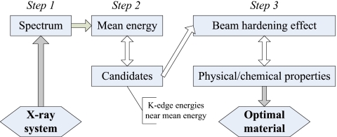
Using the K-edge discontinuity, an optimal material selection approach can be carried out in three steps, as illustrated in Fig. 3. The x-ray spectrum in step 1 can be obtained by Monte Carlo simulations and can be refined by experimental data from the system if necessary. Details of spectrum estimation can be found in Ref. 14. In step 2, as the effective energy Eeff1(l) at l=0 is still dependent on the modulator material [see Eq. 15a], the mean energy of the x-ray spectrum χ(E), defined as
| (17) |
which is totally independent of the modulator material is used as a substitute to sift and narrow down the search for the potential candidates. The elements whose K-edge energies are within Em−10 keV–Em+10 keV, based on our experience, are sufficient. This is because, in general, the mean energy is close to the effective energy Eeff1(0) and 20 keV is quite a wide span for the K-edge energy.
Figure 3.
The flow diagram of our optimal material selection approach.
Evaluation of the magnitude of beam hardening in step 3 can be implemented using Eq. 13 by inserting objects in the FOV to change the x-ray spectrum from χ(E) to χ′(E) (i.e., object filtration). The effective transmission factor with no object in the FOV αeff(0) that determines the required thickness for a specific material is chosen in advance. For a range of object filtrations, the spatial variation in αeff should be as small as possible. When evaluating the candidate materials whose K-edge energies are within Em−10 keV–Em+10 keV, the magnitude of beam hardening should first decrease as Z increases and then increase as Z continues to increase. If this is not the case, then more candidates are required to ensure that such a local minimum in beam hardening is achieved.
RESULTS
The x-ray system and spectrum
Numerical simulations and practical experiments were carried out to validate our method and to determine the optimal modulator material for our tabletop x-ray CBCT system: A CPI Indico 100 x-ray generator (CPI, Communication & Medical Products Division, Georgetown, ON, Canada), a Varian PaxScan 4030CB flat panel detector (Varian X-ray Products, Salt Lake City, UT), and a Huestis collimator (Heustis Medical, Bristol, RI). The x-ray tube has a tungsten target, a 12° target angle, and was operated with a 0.6 mm focal spot size. The x-rays generated from the tube were filtered by 1 mm of inherent aluminum plus 3 mm of equivalent aluminum due to the collimator. The CsI scintillator in the flat panel detector has a thickness of 270 mg∕cm2. No antiscatter grid was mounted in front of the detector.
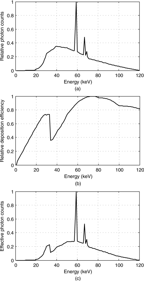
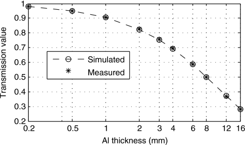
We simulated the spectrum for our x-ray system at 120 kVp using the GEANT4 Monte Carlo simulation (shown in Fig. 4).15 The x-ray spectrum χ(E) in Eq. 13 is the product of the filtered x-ray spectrum from the x-ray tube and the energy deposition efficiency of the detector (scintillator). This spectral model was validated by comparing the half-value-layer (HVL) measured on the system with the HVL calculated from the simulated spectrum. The measured HVL for our system at 120 kVp is 7.98 mm of aluminum, while the simulated HVL is 8.01 mm of aluminum. As shown in Fig. 5, the simulated transmission values for different thicknesses of aluminum match with our measurements (maximum error is 0.8%).
Figure 4.
Polychromatic spectrum of our tabletop CT system. (a) Spectrum from our x-ray tube after 4 mm of Al filtrations at 120 kVp; (b) energy deposition efficiency of our CsI scintillator with 270 mg∕cm2 of thickness; (c) spectrum of the x-ray system χ(E) in Eq. 13; it is the product of (a) and (b). When simulating the spectrum from the x-ray tube, a tungsten target with a 12° target angle was used, and three electron interactions (multiple scattering, ionization, and bremsstrahlung) and two photon interactions (photoelectric absorption and Compton scattering) were included in the physical process. The energy deposition efficiency of the scintillator was simulated by calculating the deposited energy in the scintillator, where photoelectric absorption and Compton scattering were involved.
Figure 5.
The simulated and measured transmission values for different thicknesses of aluminum.
Choosing candidates
Before choosing candidates according to their K-edge energies, it is worth briefly demonstrating that the required thickness for modulator blocker could be a limiting factor in modulator design. To make the effective transmission factor with no object in the FOV αeff(0) be 0.9 and 0.8 on our CBCT system, Table 1 lists the corresponding thicknesses of the modulator blocker for beryllium, aluminum, and copper, respectively. It is seen that if a low transmission factor (αeff(0)<0.9) is required, low Z materials (such as beryllium and aluminum) are too thick (more than 1 mm) to use.
Table 1.
The atomic numbers, densities, and the required thicknesses for beryllium, aluminum, and copper.
| Materials | Beryllium | Aluminum | Copper | |
|---|---|---|---|---|
| Atomic number | 4 | 13 | 29 | |
| Density (g∕cm3) | 1.85 | 2.70 | 8.96 | |
| Thickness | αeff(0)=0.9 | 3.6 mm | 1.0 mm | 44.0 μm |
| αeff(0)=0.8 | 8.0 mm | 2.3 mm | 105.0 μm | |
Using the x-ray spectrum in Fig. 4 and Eq. 17, the mean energy of our system Em is 62.7 keV According to our optimal material selection approach described in Sec. 3C, the K-edge energy of the optimal material most likely is between 50 and 73 keV. Table 2 lists the K-edge energies of several common metals and those whose K-edge energies are within 50–72 keV. The K-edge energies of aluminum, iron, copper, silver, gold, and lead are either too low or too high. According to these data, Z∊[64,75] are chosen as the candidate materials for our system, whose corresponding K-edge energies are from 50.3 to 71.7 keV.
Table 2.
The K-edge energies (keV) of several common metals and those whose K-edge energies are from 50 to 72 keV [Source: National Institute of Standards and Technology (Ref. 16)].
| Element | Z | K-edge |
|---|---|---|
| Aluminum (Al) | 13 | 1.6 |
| Iron (Fe) | 26 | 7.1 |
| Copper (Cu) | 29 | 9.0 |
| Silver (Ag) | 47 | 25.5 |
| Gadolinium (Gd) | 64 | 50.3 |
| Terbium (Td) | 65 | 52.0 |
| Dysprosium (Dy) | 66 | 53.8 |
| Holmium (Ho) | 67 | 55.6 |
| Erbium (Er) | 68 | 57.5 |
| Thulium(Tm) | 69 | 59.4 |
| Ytterbium(Yb) | 70 | 61.3 |
| Lutetium (Lu) | 71 | 63.3 |
| Hafnium (Hf) | 72 | 65.4 |
| Tantalum (Ta) | 73 | 67.4 |
| Tungsten (W) | 74 | 69.5 |
| Rhenium (Re) | 75 | 71.7 |
| Gold (Au) | 79 | 80.7 |
| Lead (Pb) | 82 | 88.0 |
Beam hardening for typical and candidate materials
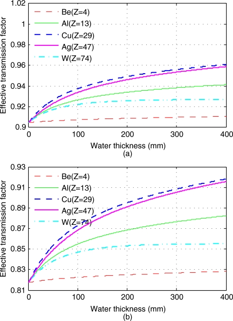
Using the x-ray spectrum in Fig. 4, we first calculated αeff(l) in Eq. 13 for beryllium (Z=4), aluminum (Z=13), copper (Z=29), silver (Z=47), and tungsten (Z=74), with object being water and l ranging from 0 to 400 mm. Two sets of simulations are demonstrated in Fig. 6, with αeff(0)=0.905 and αeff(0)=0.818, corresponding to 1.0 mm of aluminum and 25.4 μm of erbium, respectively. As mentioned in Sec. 4B, the required thicknesses for these materials are determined by the predefined αeff(0).
Figure 6.
The effective transmission factors αeff for beryllium, aluminum, copper, silver, and tungsten, with object filtrations ranging from 0 to 400 mm water. (a) αeff(0)=0.905; (b) αeff(0)=0.818.
In Fig. 6, it is shown that the effective transmission factor αeff changes with the object filtration. Since the variation in αeff represents the magnitude of beam hardening of the modulator (described in Sec. 2C), we can conclude from Fig. 6 that beryllium causes the least amount of beam hardening. Beam hardening for silver is slightly lower than that of copper. Tungsten is seen to produce even less beam hardening than aluminum. These results validate our previous argument that a higher Z material does not always generate stronger beam hardening.
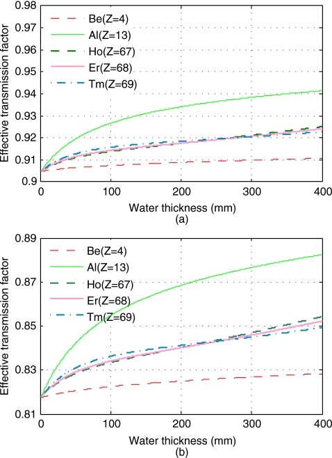
The beam hardening of the candidate materials are evaluated in the same way as in Fig. 6. After a rough comparison, the best material in terms of minimum beam hardening for our system can be further constricted to fall between holmium, erbium, and thulium. All three candidates are rare-earth metals. Figure 7 shows the effective transmission factors αeff for beryllium, aluminum, holmium, erbium, and thulium with αeff(0)=0.905 and αeff(0)=0.818, respectively. From Fig. 7, it is seen that the three materials are comparable in both cases. Holmium has a slightly lower beam hardening when the water thickness is less than 200 mm; thulium is slightly better when the water thickness is over 300 mm; while erbium is in between holmium and thulium.
Figure 7.
The effective transmission factors αeff for beryllium, aluminum, holmium, erbium, and thulium, with object filtrations ranging from 0 to 400 mm water. (a) αeff(0)=0.905; (b) αeff(0)=0.818.
Physical∕chemical properties and the optimal material
Selected physical and chemical properties for holmium, erbium, and thulium are listed in Table 3. All three elements are metallic clusters with high densities. As they all belong to the lanthanides, their chemical properties have similarities. However, erbium is more stable in air and water, and is cheaper (more abundant in the Earth’s crust).
Table 3.
Selected physical∕chemical properties for holmium, erbium, and thulium [Source: Nature’s Building Blocks: An A–Z Guide to the Elements (Ref. 17)].
| Property∕element | Holmium | Erbium | Thulium |
|---|---|---|---|
| Atomic number | 67 | 68 | 69 |
| Density | 8.80 g∕cm3 | 9.07 g∕cm3 | 9.32 g∕cm3 |
| Metallicity | Relatively soft and malleable | Soft and malleable | Soft, malleable, and ductile |
| Stability | Slowly attacked by oxygen | Slowly tarnishes in air | Slowly tarnishes in air |
| Slowly attacked by water | Very slowly reacts with water | Reacts with water | |
| Dissolves in dilute acids | Dissolves in acids | Dissolves in dilute acids | |
| Abundance (in Earth’s crust) | 1.4 ppm | 4 ppm | 0.5 ppm |
Taking both beam hardening and the physical and chemical properties into account, erbium is the optimal modulator material for our x-ray CBCT system operated at 120 kVp. When erbium is used as the modulator material, according to the numerical simulations in Figs. 67, the overall spatial variation in αeff for αeff(0)=0.905 (thickness of erbium: 12.4 μm) is only 2.2%, with water thickness l ranging from 0 to 400 mm; it is 4.3% for αeff(0)=0.818 (thickness of erbium: 25.4 μm). In contrast, the variations in αeff for copper are up to 6.2% and 12.3%, respectively, three times higher than that for erbium.
Practical experiments
On our tabletop X-ray CBCT system operated at 120 kVp, we measured the effective transmission factor αeff of 25.4 μm of copper, tungsten, and erbium foils using different combinations of aluminum (0–8 mm) and copper (0–300 μm) filtrations, simulating a range of object thicknesses. The measurement of αeff was illustrated in Fig. 1 in Sec. 3B.
For 25.4 μm of copper, erbium, and tungsten, the variations in the measured αeff with the combinations of object filtrations are 2.5%, 1.0%, and 8.6%, respectively (the measured values of αeff are listed in Table 4, where the corresponding simulated values are also given for comparison). Even though this thickness (25.4 μm) is one-fourth of the required thickness for copper given αeff(0)=0.818, erbium still outperforms copper in terms of beam hardening. Since this thickness corresponds to a relatively low transmission factor for tungsten, its variation is higher as expected. In general, the effect of beam hardening for a given material becomes worse as the material thickness increases. In Table 4, the differences between simulations and measured data can be explained by uncertainty and variability in material thickness, the abovementioned discrepancy between measured and simulated spectra, and statistical errors (up to ±0.6%) in the measured data.
Table 4.
The simulated and measured αeff for 25.4 μm of copper, erbium (the 25.4 μm of erbium foil we purchased has a thickness tolerance of ±10%), and tungsten foils with a series of added filtrations.
| Filtrationsa | 0 | 2 mm Al | 0.3 mm Cu | 2 mm Al and 0.3mm Cu | 8 mm Al and 0.3 mm Cu | Variation (%) | |
|---|---|---|---|---|---|---|---|
| Measured | Copper | 0.949 | 0.958 | 0.967 | 0.969 | 0.973 | 2.5 |
| Erbium | 0.806 | 0.806 | 0.807 | 0.808 | 0.814 | 1.0 | |
| Tungsten | 0.714 | 0.736 | 0.753 | 0.766 | 0.775 | 8.6 | |
| Simulated | Copper | 0.942 | 0.951 | 0.966 | 0.967 | 0.970 | 3.0 |
| Erbium | 0.818 | 0.825 | 0.834 | 0.835 | 0.837 | 2.3 | |
| Tungsten | 0.711 | 0.729 | 0.755 | 0.757 | 0.760 | 6.9 |
The corresponding equivalent water thicknesses are 0, 24, 114, 132, and 184 mm, respectively. They are estimated by calculating the water thickness that causes the same shift in spectrum mean energy for each of the above filter combinations.
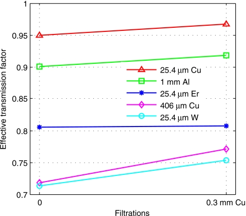
With and without 300 μm of copper in the beam, αeff for different materials, 25.4 μm of copper, erbium, and tungsten foils, 1 mm of aluminum sheet, and 406 μm of copper in a copper modulator that was deposited using PCB manufacturing, were measured on our tabletop x-ray CT system at 120 kVp (Fig. 8). The respective variations in the measured αeff are: 1.8%, 1.9%, 0.2%, 7.5%, and 5.5%. Among these materials, again we can see that erbium generates the lowest beam hardening for our x-ray system, better than aluminum, despite the fact that the aluminum sheet used was only half the thickness given the same αeff(0) of 25.4 μm thick erbium. It is also seen that the beam hardening of 25.4 μm thick tungsten is lower than that of 406 μm of copper, whose αeff(0) are quite close.
Figure 8.
The measured αeff with and without 300 μm of copper in the beam for different materials.
Therefore, erbium is the best material for our system, producing the least amount of beam hardening. Tungsten was found to prevail over copper. These experimental results are consistent with the previous numerical simulations.
CONCLUSION AND DISCUSSION
An approach for optimal modulator material selection is proposed and validated to reduce beam hardening of the primary modulator. The spatial variation in the effective transmission factor of the modulator blocker due to beam hardening caused by the modulator itself reaches a minimum when the K-edge of the modulator material is near the mean energy of the spectrum. Both numerical simulations and experimental results validate our method. Applying our method to an x-ray CBCT system operated at 120 kVp, erbium is found to be the optimal modulator material. With the transmission factor initially being 0.905 and 0.818, simulations show that erbium provides the least amount of variation as a function of object filtrations (maximum variations are 2.2% and 4.3%, respectively, nearly one-third of that for copper). With different combinations of aluminum (0–8 mm) and copper (0–300 μm) filtrations, measured variations in the effective transmission factors are 2.5%, 1.0%, and 8.6% for 25.4 μm of copper, erbium, and tungsten foils, respectively.
According to the principle of our proposed material selection approach, the optimal modulator material depends on the spectrum of the x-ray system. For different x-ray systems or for the same system but operated at different tube potentials, the optimal material will likely be different. Taking tungsten for instance, although it is not the best material for our system at 120 kVp, from Fig. 6 it can be predicted that it may outperform other materials if the tube potential is increased. In contrast, reducing the kVp to a lower level could distinguish silver from other materials. As a result, to obtain accurate scatter correction, it may be necessary to provide a series of primary modulators made of different materials that are optimized for different applications and acquisition parameters.
The investigation of the modulator material in this paper focuses on elementary substances, especially metals due to the ease of manufacturing. Compounds and metal alloys may also be worth exploring, as long as they meet the requirements in Sec. 3A. The impact of spectrum inaccuracy on the final selection of the optimal modulator material is also an important subject of our future studies. Design and evaluation of an erbium primary modulator are underway.
ACKNOWLEDGMENTS
This project is supported by NIH grants (No. R21 EB008186 and R01 HL087917), and the Lucas Foundation. The authors would like to thank Dr. Waldo Hinshaw for the insightful and valuable comments. Thanks also go to Dr. Yingkang Jin for providing the GEANT4 code of the x-ray spectrum simulation.
References
- Zhu L., Bennett N. R., and Fahrig R., “Scatter correction method for x-ray CT using primary modulation: Theory and preliminary results,” IEEE Trans. Med. Imaging 25(12), 1573–1587 (2006). 10.1109/TMI.2006.884636 [DOI] [PubMed] [Google Scholar]
- Zhu L., Starman J., Bennett N. R., and Fahrig R., “MTF measurement and a phantom study for scatter correction in CBCT using primary modulation,” in Proceedings of the IEEE Nuclear Science Symposium Conference Record, 2006, Vol. 3, pp. 1964–1968.
- Gao H., Fahrig R., Bennett N. R., Sun M., Star-Lack J., and Zhu L., “Scatter correction method for x-ray CT using primary modulation: Phantom studies,” Med. Phys. 37(2), 934–946 (2010). 10.1118/1.3298014 [DOI] [PMC free article] [PubMed] [Google Scholar]
- Brooks R. A. and Chiro G. D., “Beam hardening in x-ray reconstruction tomography,” Phys. Med. Biol. 21(3), 390–398 (1976). 10.1088/0031-9155/21/3/004 [DOI] [PubMed] [Google Scholar]
- Gao H., Zhang L., Chen Z., Xing Y., and Li S., “Beam hardening correction for middle energy industrial computerized tomography,” IEEE Trans. Nucl. Sci. 53(5), 2796–2807 (2006). 10.1109/TNS.2006.879825 [DOI] [Google Scholar]
- Joseph P. M. and Spital R. D., “A method for correcting bone induced artifacts in computed tomography scanners,” J. Comput. Assist. Tomogr. 2(1), 100–108 (1978). 10.1097/00004728-197801000-00017 [DOI] [PubMed] [Google Scholar]
- Joseph P. M. and Ruth C., “A method for simultaneous correction of spectrum hardening artifacts in CT images containing both bone and iodine,” Med. Phys. 24(10), 1629–1634 (1997). 10.1118/1.597970 [DOI] [PubMed] [Google Scholar]
- Alvarez R. E. and Macovski A., “Energy-selective reconstructions in x-ray computerized tomography,” Phys. Med. Biol. 21(5), 733–744 (1976). 10.1088/0031-9155/21/5/002 [DOI] [PubMed] [Google Scholar]
- Knoll G. F., Radiation Detection and Measurement, 3rd ed. (Wiley, New York, 2000). [Google Scholar]
- Sorenson J. A., Duke P. R., and Smith S. W., “Simulation studies of dual-energy x-ray absorptiometry,” Med. Phys. 16(1), 75–80 (1989). 10.1118/1.596405 [DOI] [PubMed] [Google Scholar]
- Fahrig R. and Yaffe M. J., “Optimization of spectral shape in digital mammography: Dependence on anode material, breast thickness, and lesion type,” Med. Phys. 21(9), 1473–1481 (1994). 10.1118/1.597191 [DOI] [PubMed] [Google Scholar]
- Fahrig R., Rowlands J. A., and Yaffe M. J., “X-ray imaging with amorphous selenium: Optimal spectra for digital mammography,” Med. Phys. 23(4), 557–567 (1996). 10.1118/1.597688 [DOI] [PubMed] [Google Scholar]
- Napolitano M. E., Trueblood J. H., Hertel N. E., and David G., “Mammographic x-ray unit kilovoltage test tool based on K-edge absorption effect,” Med. Phys. 29(9), 2169–2176 (2002). 10.1118/1.1501472 [DOI] [PubMed] [Google Scholar]
- Zhang G., Cheng J., Zhang L., Chen Z., and Xing Y., “A practical reconstruction method for dual energy computed tomography,” J. X-Ray Sci. Technol. 16(2), 67–88 (2008). [Google Scholar]
- Agostinelli S. et al. , “Geant4: A simulation toolkit,” Nucl. Instrum. Methods Phys. Res. A 506(3), 250–303 (2003). 10.1016/S0168-9002(03)01368-8 [DOI] [Google Scholar]
- http://physics.nist.gov/PhysRefData/XrayTrans/
- Elmsley J., Nature’s Building Blocks. An A-Z Guide to the Elements (Oxford University Press, Oxford, 2001). [Google Scholar]


