Abstract
Purpose: To investigate the glandular dose magnitudes and characteristics resulting from image acquisition using a dedicated breast computed tomography (BCT) clinical prototype imaging system.
Methods: The x-ray spectrum and output characteristics of a BCT clinical prototype (Koning Corporation, West Henrietta, NY) were determined using empirical measurements, breast phantoms, and an established spectrum model. The geometry of the BCT system was replicated in a Monte Carlo-based computer simulation using the GEANT4 toolkit and was validated by comparing the simulated results for exposure distribution in a standard 16 cm CT head phantom with those empirically determined using a 10 cm CT pencil ionization chamber and dosimeter. The computer simulation was further validated by replicating the results of a previous BCT dosimetry study. Upon validation, the computer simulation was modified to include breasts of varying sizes and homogeneous compositions spanning those encountered clinically, and the normalized mean glandular dose resulting from BCT was determined. Using the system’s measured exposure output determined automatically for breasts of different size and density, the mean glandular dose for these breasts was computed and compared to the glandular dose resulting from mammography. Finally, additional Monte Carlo simulations were performed to study how the glandular dose values vary within the breast tissue during acquisition with both this BCT prototype and a typical craniocaudal (CC) mammographic acquisition.
Results: This BCT prototype uses an x-ray spectrum with a first half-value layer of 1.39 mm Al and a mean x-ray energy of 30.3 keV. The normalized mean glandular dose for breasts of varying size and composition during BCT acquisition with this system ranges from 0.278 to 0.582 mGy∕mGy air kerma with the reference air kerma measured in air at the center of rotation. Using the measured exposure outputs for the tube currents automatically selected by the system for the breasts of different sizes and densities, the mean glandular dose for a BCT acquisition with this prototype system varies from 5.6 to 17.5 mGy, with the value for a breast of mean size and composition being 17.06 mGy. The glandular dose throughout the breast tissue of this mean breast varies by up to ±50% of the mean value. During a typical CC view mammographic acquisition of an equivalent mean breast, which typically results in a mean glandular dose of 2.0–2.5 mGy, the glandular dose throughout the breast tissue varies from ∼15% to ∼400% of the mean value.
Conclusions: Acquisition of a BCT image with the automated tube output settings for a mean breast with the Koning Corp. clinical prototype results in mean glandular dose values approximately equivalent to three to five two-view mammographic examinations for a similar breast. For all breast sizes and compositions studied, this glandular dose ratio between acquisition with this BCT prototype and two-view mammography ranges from 1.4 to 7.2. In mammography, portions of the mean-sized breast receive a considerably higher dose than the mean value for the whole breast. However, only a small portion of a breast undergoing mammography would receive a glandular dose similar to that from BCT.
Keywords: breast CT, dosimetry, Monte Carlo, digital mammography
INTRODUCTION
Dedicated breast computed tomography (BCT) is being investigated as a new x-ray based tomographic breast imaging method for early breast cancer detection and∕or diagnosis.1, 2, 3, 4, 5, 6, 7, 8, 9, 10, 11, 12, 13 BCT involves the adaptation of standard whole body computed tomography (CT) to breast cancer imaging. This involves not only changing the acquisition geometry to limit the primary x-ray beam to include only the breast but also optimizing the acquisition parameters to the needs of breast cancer imaging, namely, higher contrast and spatial resolution. To increase the contrast resolution of BCT, required to distinguish the different soft tissues in the breast, the energy of the x-ray spectra in BCT is significantly lower than that of whole body CT.11, 13 However, to maintain reasonable levels of radiation dose to the imaged breast, these spectra are of considerably higher energies than that used in mammography.
To the best of our knowledge, currently only two types of BCT systems are being used for patient imaging studies. The systems built and described by Boone et al.,1, 4, 6, 7, 13 when used for patient imaging, use an x-ray spectrum output by a tungsten anode, with a tube voltage of 80 kVp, with additional copper filtration, resulting in a spectrum with first half-value layer (HVL) of 5.7 mm Al.14 Patient acquisitions with this system result in mean glandular doses that range from 2.5 to 10.3 mGy,13 based on results of dosimetry calculations performed by Boone et al.4, 14
The second type of BCT system being used for patient trials is a commercial prototype system (Koning Corporation, West Henrietta, NY), which has been previously described.2, 3, 5, 11, 15, 16 Although the general design concepts of this system are similar to those of the Boone BCT systems (in terms of patient positioning, x-ray tube travel path, cone beam acquisition, etc.), the Koning BCT system uses a substantially different x-ray spectrum: Tungsten anode, tube voltage of 49 kVp, and additional aluminum filtration. Given the differences in the x-ray spectrum used by this system, compared to those studied by Boone et al., in addition to other geometrical differences and the inclusion of automated tube output settings on the Koning system, it is of interest to perform a comprehensive characterization of the dosimetry properties of this system.
In addition, the mean glandular dose, used for breast dosimetry, is a global measure of dose that encompasses the whole imaged breast. However, it is expected that due to the higher energies used in BCT, in addition to the variable entrance surface during exposure due to the rotation of the x-ray tube around the entire breast, the distribution of energy deposition in the breast tissue in BCT is very different from that in standard mammography. Thacker and Glick17 showed the distribution of energy deposition during BCT for some monochromatic x-ray energies, but these distributions were not studied for x-ray spectra, and a comparison to dose distributions resulting from mammography has not been reported.
In this study, empirical measurements and computer simulations of a Koning BCT system recently installed at our institution were performed to investigate the resulting mean glandular dose to the breast for the specific acquisition protocols used by the system. Additional computer simulations were performed to study the differences in dose deposition during BCT acquisition and standard screen-film mammography.
METHODS AND MATERIALS
To characterize the radiation dose resulting from the acquisition of BCT images with the Koning BCT prototype, first the system’s x-ray spectrum and the x-ray exposure levels automatically selected by the system’s imaging software were empirically investigated. Then a Monte Carlo simulation program of the acquisition system was developed and validated by comparing its predictions to empirical measurements. Finally, the simulation program was used to determine the mean glandular dose from a BCT scan of breasts of different sizes and compositions.
Dedicated breast computed tomography system
Details on the Koning BCT prototype clinical systems such as the one installed at our institution have been published previously,11, 15, 18 so here we will only describe the system’s features most relevant to this study. The main component of the BCT prototype consists of a tabletop on which the patient lies prone, under which there is a tungsten anode x-ray tube and a flat panel digital x-ray detector. The tabletop includes a hole through which the breast being imaged is pendant. The x-ray tube is positioned so that the central ray traverses the patient’s chest wall, and the x-ray beam is collimated to a half-cone. To separate the moving components of the system from the patient, a 2 mm thick polycarbonate “cup” extends from the bottom of the tabletop, centered at the center of the tabletop hole, with a 40 cm diameter at the top, decreasing to 25 cm at the base, and a height of 32 cm.
During acquisition, the x-ray tube and the flat panel detector rotate around a vertical axis located at the center of the hole for the breast. A complete BCT scan entails the acquisition of 300 projections over a full 360° revolution of the x-ray tube and detector in 10 s. The x-ray tube operates in pulsed mode, with a constant 8 ms pulse length and a tube voltage of 49 kVp. To select the appropriate tube current for each breast to be imaged, the system acquires two low-dose projection (16 mA, 2 pulses of 8 ms each per projection) images normal to each other, and the signal at a region of interest (ROI), positioned by the user in the approximate midline of the breast close to the chest wall, is analyzed. According to the signal level inside the two ROIs, the tube current to be used during the acquisition of the BCT projections is selected from 13 predefined settings which range from 12 to 200 mA.
X-ray tube characterization
As mentioned above, the BCT system’s x-ray tube operates at a voltage of 49 kVp and uses a tungsten target and added aluminum filtration, but additional information is needed to perform an accurate dosimetric estimation. For this, a standard CT 10 cm pencil ionization chamber (model 10X6-3CT, Radcal Corp., Monrovia, CA) connected to a dosimeter (Radcal ACCU-DOSE 2186, Radcal Corp, Monrovia, CA) was placed at the center of rotation (65 cm from the focal spot and 27.3 cm from the detector), with the uppermost portion of the active volume of the chamber at the central ray of the x-ray beam and the exposure output for a single projection was measured. Several additional thicknesses of aluminum were placed at the exit port of the x-ray tube, and the resulting exposure was measured again. For accuracy, three exposure measurements were performed at each aluminum thickness and the results averaged. With this information, the first HVL of the x-ray spectrum was calculated and a spectral model was developed using the x-ray spectra models published by Cranley et al.19 and attenuation coefficients published by NIST.20 The spectral model was developed by matching the HVL of the model to the empirically determined one by varying the thickness of the modeled system’s aluminum filter. The exposure data acquired with the different aluminum thicknesses were also compared to the expected exposures resulting from our spectral model. These exposure measurements, just like all others described below, were converted to air kerma (1 mGy=114.5 mR).
To determine the relationship between x-ray tube output exposure and tube current setting, the total exposure at the center of rotation during a complete BCT scan was measured with the pencil ionization chamber placed as described above with no additional aluminum filtration (except that included in the system), while the tube current was varied from 16 to 200 mA. To obtain more accurate results, the measurement at each tube current setting was repeated three times and the results averaged. The BCT system’s x-ray tube output had recently been calibrated by the manufacturer before these measurements were performed.
Monte Carlo simulation
A C++ based Monte Carlo simulation program of the Koning BCT system was developed and implemented using the GEANT4 toolkit for Monte Carlo simulations (version 9.3),21, 22 based on similar, previously described simulation programs.23, 24, 25 With this program, the mean glandular radiation dose deposited in simulated breasts of varying size and composition during a simulated BCT scan was determined.
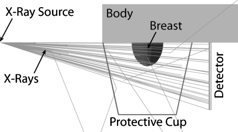
The Monte Carlo simulations included the pendant breast, simulated as a semiellipsoid, with a 1.45 mm layer of skin,26 the body (to include any possible x-ray backscatter) as a volume of water, the system’s polycarbonate protective cup, the flat panel detector, detector cover, and the x-ray point source (Fig. 1). The breast sizes studied were selected to represent the entire range from small to large sized breasts, using the data published by Boone et al.,4 and the breast compositions studied ranged from 1% glandular fraction to 100% glandular fraction, including a 14.3% glandular fraction, which was recently shown to be the glandular fraction of an average breast (skin excluded).27 Although that publication by Yaffe et al.27 showed that patient breasts rarely have glandular fractions above 45%, in this study we included results for breasts up to 100% glandular fraction to continue what has traditionally been reported in previous breast dosimetry studies and to allow for easier comparison of our results with previous studies. The chemical composition of the glandular and adipose tissues was defined as reported by Hammerstein et al.28 Table 1 shows the distribution of breast sizes and glandular fractions that were included in this study.
Figure 1.
Geometry of the Monte Carlo simulation of the dedicated breast computed tomography clinical prototype and the patient. The breast was simulated as a semiellipsoid with varying diameter, chest wall-to-nipple distance, and homogeneous composition. The body, composed of water, was simulated as a right cuboid to include the effects of backscatter.
Table 1.
DgNCT for the semiellipsoidal breasts included in this study, in mGy∕mGy air kerma. The reference air kerma is for that at the center of rotation. The diameter of the semiellipsoidal breasts was based on the range of patient values found by Boone et al. (Ref. 4). The values for chest wall-to-nipple distance were set to be 0.5, 0.75, and 1.0 times the breast diameter. Breasts with a glandular fraction of 14.3% represent breasts with an average composition (Ref. 27).
| Diameter at chest wall (cm) | Chest wall-to-nipple distance (cm) | Glandular fraction (%) | |||||
|---|---|---|---|---|---|---|---|
| 1 | 14.3 | 25 | 50 | 75 | 100 | ||
| 10 | 5 | 0.537 | 0.517 | 0.502 | 0.469 | 0.438 | 0.410 |
| 10 | 7.5 | 0.566 | 0.544 | 0.527 | 0.490 | 0.457 | 0.427 |
| 10 | 10 | 0.582 | 0.559 | 0.541 | 0.503 | 0.468 | 0.436 |
| 12 | 6 | 0.494 | 0.474 | 0.458 | 0.424 | 0.395 | 0.367 |
| 12 | 9 | 0.521 | 0.499 | 0.482 | 0.445 | 0.412 | 0.382 |
| 12 | 12 | 0.536 | 0.512 | 0.493 | 0.455 | 0.420 | 0.389 |
| 14 | 7 | 0.458 | 0.437 | 0.421 | 0.388 | 0.358 | 0.331 |
| 14 | 10.5 | 0.482 | 0.459 | 0.442 | 0.406 | 0.374 | 0.345 |
| 14 | 14 | 0.494 | 0.470 | 0.452 | 0.414 | 0.381 | 0.350 |
| 16 | 8 | 0.425 | 0.404 | 0.389 | 0.357 | 0.328 | 0.302 |
| 16 | 12 | 0.448 | 0.425 | 0.408 | 0.373 | 0.341 | 0.314 |
| 16 | 16 | 0.458 | 0.434 | 0.416 | 0.379 | 0.346 | 0.318 |
| 18 | 9 | 0.397 | 0.376 | 0.361 | 0.330 | 0.302 | 0.278 |
| 18 | 13.5 | 0.417 | 0.395 | 0.378 | 0.343 | 0.313 | 0.287 |
| 18 | 18 | 0.425 | 0.402 | 0.384 | 0.348 | 0.317 | 0.290 |
To obtain results for the empirically characterized x-ray spectrum, each MC simulation involved the emission and tracking of 106 x rays of the same energy ranging from 15 to 49 keV in 0.5 keV steps, while recording each energy deposition in the breast tissue, using the method of Boone29 and Wilkinson and Heggie.30 The monochromatic results were then combined as described by Boone31 using the determined model of the x-ray spectrum as described above, resulting in a value for the normalized mean glandular dose (DgNCT) in units of milligray per milligray air kerma at the center of rotation, for each breast size and composition. Due to the symmetric nature of the simulated geometry, the simulation of only a single projection acquisition was required to obtain the DgNCT results for the full BCT scan.
To verify that the tracking of 106 x rays at each x-ray energy provides sufficient statistical precision, the Monte Carlo simulation for the smallest, least dense breast studied (chest wall-to-nipple distance=5 cm, diameter at chest wall=10 cm, and glandular fraction=1%) for the minimum and maximum x-ray energies (15 and 49 keV) was repeated five times, and the coefficient of variation (COV=100σ∕μ) of the resulting monoenergetic normalized mean glandular dose was calculated.
Validation of Monte Carlo simulations
To validate the Monte Carlo simulation of the BCT system, a standard 16 cm CT head phantom was placed at the top of the tabletop hole in the Koning BCT system, where the patient’s breast would be normally located. The center of the phantom was located at the center of rotation of the system, and the 10 cm CT pencil ionization chamber was placed at the center hole of the phantom. Both full BCT scans and a single projection were acquired, and the resulting exposure at the center insert location was recorded. Similar measurements were obtained with the CT pencil chamber placed in each of the four perimeter hole positions.
In a similar fashion, in the Monte Carlo simulation, the simulated breast was replaced with a standard CT head phantom, and the simulation of the acquisition of a BCT scan was performed. The phantom was simulated with the same dimensions as the physical phantom (polymethyl methacrylate cylinder with a diameter of 16 cm and a height of 15 cm). Due to symmetry, the acquisition of only the first 75 projections (spanning 90°) of the 300 projections that the Koning BCT system acquires during a complete 360° rotation was simulated. During each simulation, the energy deposited in the volumes occupied by the five standard inserts of the standard head CT phantom (1.31 cm in diameter, 10 cm in height, perimeter inserts located 1 cm from the phantom edge) was recorded.
The relative variation in exposure at each of the five insert positions normalized to the values for the center position was compared for both a single projection and for a full BCT scan. To further validate our Monte Carlo simulation program, it was modified to replicate the BCT imaging conditions described by Boone et al.4 as closely as possible and the simulations necessary to compare some of the results presented in that work were performed. Specifically, the spectral DgNCT for the breasts with even-numbered diameter at the chest wall shown in Fig. 15(b) of the study of Boone et al. were included in this comparison.
Statistical comparisons between the empirical measurements and the Monte Carlo results and between our and the results of Boone et al. were performed using commercial software (TABLECURVE 2D, version 5.01.03, Systat Software, Inc., Chicago, IL and SPSS STATISTICS 17.0, SPSS, Inc., Chicago, IL).
Automatic tube current settings
The Monte Carlo simulation results, namely, the normalized mean glandular dose, provide the estimated mean glandular dose to a homogeneous breast of a specific size and glandular fraction per unit air kerma at the center of rotation when the air kerma is measured in air with the same technique factors as those used for the imaging of the breast. However, when the acquisition technique is set using the recommended automatic method based on the analysis of two low-dose projections, as described above, the air kerma at the center of rotation will be set for specific breast sizes and glandular fractions. Therefore, to determine what the actual mean glandular dose would be for breasts of specific sizes and compositions, the tube current set by the automatic method for different breasts with different sizes and compositions was investigated. For this, liquid cylinders within thin plastic-lined vessels were used to represent breast phantoms. First, a 10 cm diameter water cylinder (plastic lining thickness of 0.80 mm) was used to represent 100% breast glandular tissue and placed in the BCT system where the patient breast would be positioned, and a single low-dose projection image was acquired. Since the cylinder had a circular cross section, the second projection normal to the first was not acquired. To compute the automatic tube current setting, the ROI to be analyzed was placed at the horizontal midline of the cylinder projection, with its center 75 pixels below the top edge of the image, which was deemed representative of the positioning of the ROI during patient scanning. From this low-dose projection, the system software determined what the tube current setting for the BCT scan should be, as described above. This was repeated with an olive oil cylinder, to represent 100% breast adipose tissue.32 The same process was repeated for cylinders with diameters of 12 cm (lining thickness: 1.60 mm), 14 cm (lining thickness: 2.24 mm), and 16 cm (lining thickness: 2.24 mm). The diameters that resulted in a different automatic tube current setting for olive oil or water were then replaced with varying homogeneous mixtures of the two liquids, to represent equivalent glandular fractions of 14.3%, 25%, 50%, and 75%. To obtain the homogeneous mixtures of water and olive oil, a hand-held electric mixer was used to perform the mixing. An 18 cm diameter cylinder was not used since the 16 cm olive oil cylinder already resulted in an automatic tube current setting of 200 mA, the system’s maximum.
With these data, and the measurements of exposure at the center of rotation for different tube currents, as described previously, the mean glandular dose to breasts of certain specific sizes and compositions could be estimated. These estimates were compared to the mean glandular dose values reported by Boone et al.14 for equivalent breasts, in terms of size and composition, undergoing two-view screen-film mammography. For this comparison, the compressed breast thicknesses of the breasts undergoing mammography were converted to equivalent breast diameters at the chest wall using the relationship published in the same paper, and interpolation was performed on the BCT mean glandular dose values to obtain the corresponding values for these equivalent diameters. For this comparison, only the results of the medium chest wall-to-nipple breast sizes were used since this dimension does not introduce a large variation in mean glandular dose.
Distribution of dose deposition
To investigate how this distribution differs throughout the breast for this BCT prototype, and what dose levels different sections of breast tissue are subjected to during BCT and mammography, additional Monte Carlo simulations were performed to simulate both modalities. These simulations recorded the energy deposition events in the breast during BCT and mammography acquisition along with the position of the event.
For BCT, the same geometry described above was used, with the breast specified as of mean size and composition: A chest wall-to-nipple distance of 10.5 cm, a diameter at the chest wall of 14 cm, and a glandular fraction of 14.3%, including a breast skin layer of 1.45 mm.26, 27, 31 The BCT acquisition simulation was performed in the same manner described above, but for this simulation 109 x rays of each energy were tracked and the location and amount of energy deposition in the breast tissue (excluding the skin tissue) was recorded. These data were recorded by dividing the breast volume into voxels of 0.1×0.1 mm2 in the coronal plane and 1.0 mm in the posterioanterior direction. Due to symmetry, only a single BCT projection acquisition was simulated, and the resulting energy deposition distribution for the complete BCT scan was calculated by rotating and summing the single projection results over 300 angles comprising 360°.
For simulation of mammography acquisition, the geometry used was that of the craniocaudal (CC) view previously described,25 with a compressed breast thickness of 5 cm, a chest wall-to-nipple distance of 12 cm, a length along the chest wall of 24 cm, a glandular fraction of 14.3%, and a breast skin layer of 1.45 mm, which also represents a breast of mean size and composition. In this case, 109 x rays of each energy between 10 and 28 keV in 0.5 keV steps were simulated and tracked as described above, and the results combined using the relative x-ray fluence of a modeled spectrum according to Cranley et al.19 for a molybdenum target x-ray tube, with a 30 μm molybdenum filter, a 0.8 mm Be window, and a tube voltage of 28 kVp. This spectrum results in a mean x-ray energy of 16.2 keV and a first HVL of 0.277 mm Al, which, if measured empirically after 60 cm of air and a 2 mm breast compression plate, would result in a mean energy of 16.8 keV and a first HVL of 0.339 mm Al. Since our Monte Carlo simulations include the air and the breast compression plate, the spectral model without these two components was used to combine the monoenergetic results. The CC view breast volume was divided into 1.0×1.0 mm2 voxels in the transverse plane and 0.1 mm in the x-ray tube to detector direction.
For both the BCT and CC view acquisition simulations, to perform the computations in a reasonable time frame, Emory University’s ELLIPSE high performance computer cluster with 1024 computing cores (Opteron 2.6 GHz CPUs, Advanced Micro Devices Inc., Sunnyvale, CA) was used.
To study the resulting dose deposition distributions, the energy deposition results were divided by the mass of each voxel, and the results normalized to a mean value of unity. To avoid some distortion of the results due to noisy data at the edges of the breast volumes where the voxels included only a small fraction of breast tissue, the data in the voxels that were not fully inside the breast tissue were discarded before normalization. This resulted in a removal for the BCT of 3.12% of the voxels, which involved 1.55% of the total mass of the breast, while for the CC simulation, 2.40% of the voxels were discarded, representing 1.21% of the total mass. The dose deposition distributions were analyzed using Interactive Data Language (IDL, ITT Visual Information Solutions, Boulder, CO) to generate contour figures and dose distribution histograms.
RESULTS
X-ray tube characterization
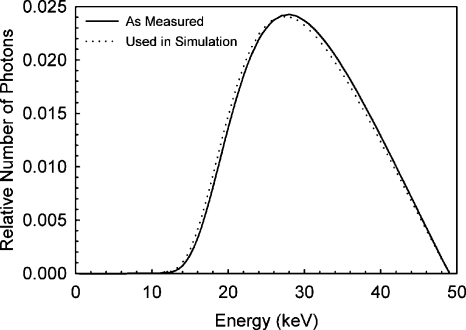
The first HVL of the x-ray spectrum was calculated to be 1.39 mm Al, resulting in a spectral model, as shown in Fig. 2, with a mean photon energy of 30.3 keV. To match this HVL with the modeled spectrum, the system’s aluminum filter had to be modeled to be 1.576 mm thick, which is within 1.5% of the known thickness of the actual aluminum filter installed in the system. Since the Monte Carlo simulation geometry included air and the protective cup, the modeled x-ray spectrum actually used to combine the monochromatic results of the simulation was modified to exclude the effects of the attenuation of these two materials. This adjustment resulted in a modeled x-ray spectrum with a first HVL of 1.32 mm Al, and the small difference in the spectrum can be seen in Fig. 2.
Figure 2.
Model of the x-ray spectrum output by the BCT prototype, according to empirical measurements and the x-ray spectra cataloged by Cranley et al. (Ref. 19). The half-value layer of the BCT prototype spectrum was determined to be 1.39 mm Al and the mean photon energy was 30.3 keV. The spectrum used to combine the Monte Carlo simulation results differs slightly from that measured since the simulations included the air and the protective cup, so the effects of these did not need to be included in the x-ray spectrum model.
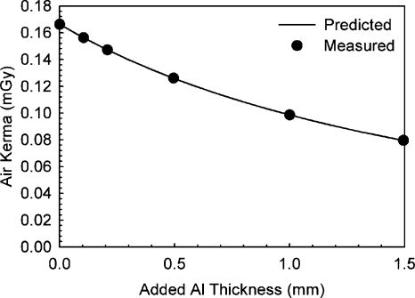
The comparison between predicted exposure after several different thicknesses of aluminum and measured exposure resulted in an excellent match, with a maximum deviation for the predicted exposures of 0.82%. Figure 3 shows the measured and predicted variations in exposure.
Figure 3.
Validation of the BCT prototype x-ray spectrum model by comparison of the predicted exposure after varying thicknesses of added aluminum and those measured empirically. Excellent agreement was found.
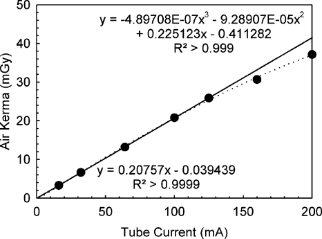
Figure 4 shows the measured relationship between tube current during BCT acquisition and mean exposure at the center of rotation. Although the relationship was found to be linear up to 125 mA, substantial deviation from a linear relationship was detected for the two tube current settings available beyond this value (160 and 200 mA), although the system had been recently calibrated. For example, the exposure measured for a tube current of 200 mA was only 78.7% higher than that measured for 100 mA. The solid line in Fig. 4 is a linear fit of the measurements up to and including 125 mA, while the dashed line is a polynomial fit for all data. The system manufacturer expressed that the measured nonlinearity might be due to a limitation of the calibration of the generator but that it was still within the tolerance specifications.
Figure 4.
Measurement of x-ray output linearity for the BCT prototype for full BCT scans. A deviation from the expected linearity was found for the two highest user-selectable tube currents (160 and 200 mA). The fitted lines correspond to a fit using only the data below 160 mA (solid line) and all measured data points (dashed line).
Validation of Monte Carlo simulations
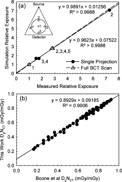
Figure 5a shows the comparison of the relative variation in exposure at the five insert positions of the CT head phantom normalized to the values for the center position, obtained with the Monte Carlo simulations and with the empirical measurements, for both a single projection and for a full BCT scan. The figure also includes the resulting linear fits for both sets of comparisons. For position 5, during the acquisition of a single projection, the exposure did not reach the minimum threshold for the dosimeter in pulsed mode to start acquisition, so a comparison for this position is not included. An excellent correspondence in values was found for both the single projection and the full BCT scan. For both linear fits, the slope coefficients are not significantly different from 1 and the y intercepts are not significantly different from 0. In addition, for both the single projection and the full scan the simulation results were not significantly different from the measurements (Wilcoxon signed-rank test,p=0.593 and p=0.257, respectively).
Figure 5.
Validation of the Monte Carlo simulation. (a) Comparison of the predicted exposure distribution at the five insert positions of a 16 cm diameter standard CT head phantom to that measured empirically. The comparison was performed for both the acquisition of a single projection and for a full BCT scan. The diagram in the top left corner identifies the relative position of the inserts compared to the x-ray source and detector. Excellent agreement was found. (b) Comparison of spectral DgNCT (mGy∕mGy) as determined by Boone et al. for a set of breast sizes and the equivalent values determined by our Monte Carlo simulation after modification to match the imaging conditions of Boone et al. Good agreement was found.
Figure 5b shows the comparison between the DgNCT data included in Fig. 15b of the paper by Boone et al.4 and the DgNCT values determined by our Monte Carlo simulation program modified to modify that paper’s imaging conditions. Good correspondence can be seen, although the values were found to be significantly different (p<10−6) and the fit coefficients were significantly different from 0 (y-intercept) and 1 (slope). A possible reason for the difference in the results could be an imperfect match of the x-ray spectrum models used.
Monte Carlo simulation
The COVs for the five Monte Carlo simulations for x-ray energies of 15 and 49 keV were 0.65% and 0.55%, respectively. This shows that the emission and tracking of 106 x rays at each x-ray energy provides results with enough statistical precision.
The results for the normalized mean glandular dose (DgNCT) for the different breast sizes and compositions included in the simulation are shown in Table 1. As expected, DgNCT decreases with increasing glandular fraction, increasing breast diameter, and increasing chest wall-to-nipple distance. These trends were also shown by Boone et al.31 and Thacker and Glick.17
Automatic tube current settings
Table 2 shows the tube current settings that were automatically selected by the image acquisition software of the BCT system when analyzing the low-dose single projections of the water and olive oil cylinders with varying concentration. Since the maximum tube current for the system is 200 mA, whenever this value was automatically selected by the system, larger diameter cylinders or higher glandular density mixtures were not investigated since it is known this would result in a setting of 200 mA.
Table 2.
Tube current settings automatically selected by the BCT system’s image acquisition software for the liquid cylinders with thin plastic lining with different diameters composed of either water (representing 100% glandular tissue), olive oil (representing 100% adipose tissue), or a homogeneous mixture of the two. Larger breast diameters, or same breast diameters with a higher proportion of glandular tissue composition would always result in a higher mA, if available. Thus, for conditions that resulted in automatic settings of 200 mA, the BCT system’s maximum, larger cylinders, or higher glandular fractions were not tested since it was assumed that they would also result in an automatic setting of 200 mA [these cases are marked with an asterisk ( *)].
| Diameter at chest wall (cm) | Equivalent glandular fraction (%) | |||||
|---|---|---|---|---|---|---|
| 0 | 14.3 | 25 | 50 | 75 | 100 | |
| 10 | 50 | 64 | 64 | 80 | 100 | 125 |
| 12 | 80 | 100 | 125 | 160 | 160 | 200 |
| 14 | 160 | 200 | 200* | 200* | 200* | 200* |
| 16 | 200 | 200* | 200* | 200* | 200* | 200* |
The tube current values listed here were used to compute the exposure at the center of rotation for corresponding BCT scans of breasts of these sizes and compositions, and therefore the actual mean glandular dose for BCT scanning of these breasts could be computed. The resulting values are listed in Table 3.
Table 3.
Mean glandular dose (in mGy) for the breasts of varying sizes and compositions, according to the Monte Carlo simulation results combined with the tube current settings automatically selected by the BCT system for breast phantoms of equivalent size and composition. For breast sizes and compositions not tested in Table 2, a tube current of 200 mA was assumed.
| Diameter at chest wall (cm) | Chest wall-to-nipple distance (cm) | Glandular fraction (%) | |||||
|---|---|---|---|---|---|---|---|
| 1 | 14.3 | 25 | 50 | 75 | 100 | ||
| 10 | 5 | 5.57 | 6.85 | 6.65 | 7.77 | 9.07 | 10.60 |
| 10 | 7.5 | 5.87 | 7.21 | 6.99 | 8.13 | 9.48 | 11.06 |
| 10 | 10 | 6.03 | 7.41 | 7.18 | 8.33 | 9.69 | 11.29 |
| 12 | 6 | 8.19 | 9.81 | 11.86 | 13.01 | 12.10 | 13.63 |
| 12 | 9 | 8.64 | 10.33 | 12.47 | 13.65 | 12.63 | 14.19 |
| 12 | 12 | 8.88 | 10.60 | 12.77 | 13.94 | 12.88 | 14.46 |
| 14 | 7 | 14.03 | 16.21 | 15.64 | 14.41 | 13.31 | 12.31 |
| 14 | 10.5 | 14.78 | 17.06 | 16.43 | 15.06 | 13.88 | 12.81 |
| 14 | 14 | 15.15 | 17.46 | 16.79 | 15.39 | 14.13 | 13.01 |
| 16 | 8 | 15.78 | 15.02 | 14.46 | 13.25 | 12.18 | 11.23 |
| 16 | 12 | 16.62 | 15.79 | 15.17 | 13.83 | 12.67 | 11.65 |
| 16 | 16 | 16.99 | 16.11 | 15.46 | 14.07 | 12.86 | 11.79 |
| 18 | 9 | 14.73 | 13.98 | 13.42 | 12.25 | 11.23 | 10.31 |
| 18 | 13.5 | 15.49 | 14.66 | 14.04 | 12.75 | 11.64 | 10.65 |
| 18 | 18 | 15.77 | 14.91 | 14.27 | 12.93 | 11.77 | 10.75 |
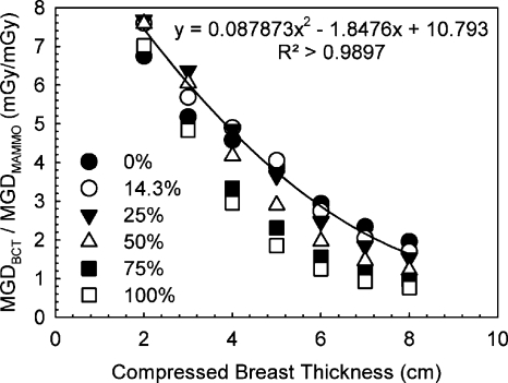
Figure 6 shows the relationship found between mean glandular dose due to a single BCT acquisition with the Koning Corp. prototype system and a two-view mammography acquisition as reported by Boone et al.14 Piecewise linear interpolation of the results in Table 3 had to be performed to obtain values that correspond to the breast sizes reported on by Boone et al. A second-order polynomial fit to the data for the breast with mean composition (14.3% glandular fraction) is also shown.
Figure 6.
Mean glandular dose comparison between the studied BCT prototype and two-view screen-film mammography for breasts of different sizes and glandular fractions. The equivalency between compressed breast thickness and breast diameter and the mammography dose values was obtained from Boone et al. (Ref. 14).
Distribution of dose deposition
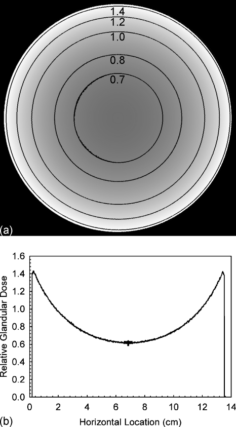
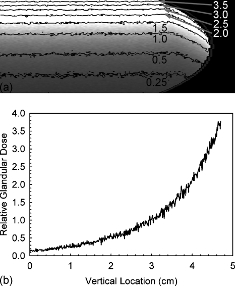
Figure 7 shows the coronal slice of the relative glandular dose deposition through the breast’s center of mass with contour lines for several values. The horizontal profile through the center of this slice is also included in Fig. 7. It can be seen that the glandular dose in this slice varies between ∼65% and ∼140% of the mean glandular dose of the entire breast. Figure 8 shows similar information for the compressed breast undergoing CC view mammographic acquisition, although in this case, for enhanced visibility, only the right half of the breast slice is shown (the left half is a mirror image) and the dose profile shown is for the vertical profile through the center of mass. In the case of mammographic acquisition, it can be seen that the glandular dose varies between ∼15% to ∼400% of the mean glandular dose.
Figure 7.
(a) Coronal slice through the breast’s center of mass showing the glandular dose distribution for a BCT acquisition normalized to a mean value of unity, with contour lines added. For better visibility of the contour lines, these data were smoothed using a mean filter with a 5×5 kernel size. (b) Horizontal profile through the center of the shown slice. These data were not smoothed.
Figure 8.
(a) Right half of the coronal slice through the breast’s center of mass showing the glandular dose distribution for a CC view mammographic acquisition normalized to a mean value of unity, with contour lines added. For better visibility of the contour lines, these data were smoothed using a mean filter with a 5×5 kernel size. (b) Vertical profile through the center of mass of the breast (leftmost column of the shown slice). These data were not smoothed.
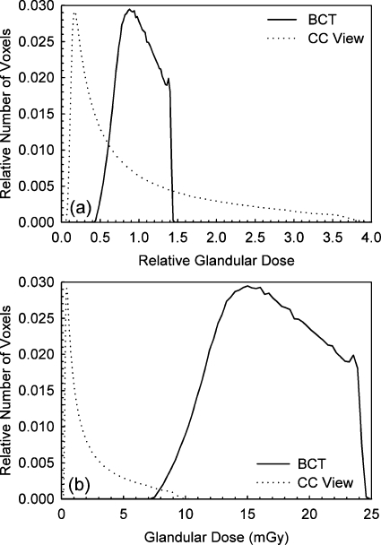
Figure 9a shows the histograms of relative glandular dose value distributions for the entire breast undergoing BCT and mammographic acquisition. It can be clearly seen that for BCT acquisition with this prototype, the magnitude of glandular dose throughout the entire breast is concentrated around the mean glandular dose much more than for mammography, with a maximum deviation from the mean of approximately ±50%. For the CC view distribution, although most tissue receives less glandular dose than the mean (64% in this case), the glandular dose closest to the entrance surface can be up to four times that of the mean.
Figure 9.
(a) Histograms of the normalized glandular dose distributions for both the BCT and the CC view mammographic acquisitions of a breast of mean size and composition. The glandular dose values were normalized to a mean of unity. The narrower distribution of values for the BCT acquisition can be easily seen. (b) Histograms of the glandular dose distributions for both the BCT and the CC view mammographic acquisitions assuming mean glandular doses of 17.6 mGy for BCT and 2.5 mGy for the CC view.
Figure 9b shows the glandular dose value distributions for the entire breast undergoing BCT and mammographic acquisition if the BCT and the CC view mammography result in mean glandular doses of 17.06 and 2.5 mGy, respectively.
DISCUSSION
According to Boone et al.,14 a 14 cm diameter breast corresponds to a 5 cm thick compressed breast, which, if composed of a 0%–50% glandular fraction, results, on the average, in a mean glandular dose due to two-view screen-film mammography of approximately 4–5 mGy. According to the results of this study, imaging a similar breast with the dedicated BCT system manufactured by Koning Corp., using the system’s automated tube output settings, would result in a mean glandular dose of 14.0–17.5 mGy. This would indicate that one BCT acquisition of an average breast with this system is equivalent in mean glandular dose to approximately three to five two-view mammographic examinations. Furthermore, for the range of breast sizes and compositions studied, it was found that the ratio between the mean glandular dose of a BCT acquisition with this prototype to that of a two-view screen-film mammographic acquisition varies between 1.4 and 7.2. According to Hendrick et al.,33 in 4366 cases studied from the Digital Mammographic Imaging Screening Trial (DMIST), digital mammography resulted in 22% lower mean glandular dose per view than screen-film mammography, so the dose ratio between BCT with this prototype and two-view digital mammography would probably be higher for the range of breast sizes and compositions studied.
From the dose deposition distribution results, we expected and showed that BCT’s use of higher energy x rays and varying angular incidence results in a more consistent glandular dose level throughout the entire breast compared to that in mammography. However, although the glandular dose variation throughout the breast tissue in mammography is considerably larger than that of this BCT prototype, the mean glandular dose difference between these modalities is large, so only a small portion of the breast tissue undergoing mammography receives a glandular dose equivalent to some portions of the breast undergoing BCT. Of course, for this voxel-based comparison to be complete, the fact that mammographic acquisition is always performed with at least two views (in the case of screening) and, in general, with four to six views (in the case of diagnostic work-up) should be taken into account. However, for this an understanding of the internal location of the same breast tissues during breast recompression for the CC view and mediolateral oblique or other views would be necessary, which is beyond the scope of this study.
Furthermore, the results of this study, especially those of the dose distributions within the breast tissue, are affected by the assumption that the breast is composed of a homogeneous mixture of adipose and glandular tissue. Although this is known to not be an accurate representation of reality, given the great variation in breast glandular tissue encountered clinically, this is an accepted approximation to make the investigation of breast dosimetry possible, and at least allows for a comparison among protocols, technologies, and∕or modalities rather than for the assignment of absolute dose values to individual patients.
CONCLUSION
Empirical measurements were performed to characterize the x-ray spectrum and exposure levels used by the dedicated BCT clinical prototype imaging system manufactured by Koning Corp. The system’s geometry was replicated in a Monte Carlo-based computer simulation to obtain normalized mean glandular dose values for simulated breasts of different sizes and compositions, encompassing those encountered clinically. The empirical and simulation results were combined to determine both the mean glandular dose values to these breasts and the distribution of glandular dose values within the breast tissue. Finally, these were compared to glandular dose distributions and mean values for standard mammography.
This investigation showed that the mean glandular dose values for BCT acquisition using the automatic tube current settings with this clinical prototype vary from 5.5 to 17.5 mGy, which is from 1.4 to 7.2 times that of a two-view screen-film mammographic acquisition, depending on the breast size and composition. Lower dose values have been reported previously for BCT systems with different characteristics.13, 14 In addition, lower dose values would result if this system is used with lower tube current settings than those automatically suggested by the system, although the impact of these settings on image quality would have to be investigated. Furthermore, this investigation showed that during a BCT acquisition with this prototype, the glandular dose distribution inside the breast can vary by up to ±50% of the mean value. For a typical mammographic acquisition the glandular dose distribution varies from ∼15% to ∼400% of the mean. It must be noted that although it can be expected that only one BCT acquisition will be acquired of each breast for any noncontrast enhanced examination, mammographic acquisitions are always performed with at least two views or more.
Finally, it must be noted that relating this dosimetric information to actual increased risk of cancer development is beyond the scope of this study and a subject of ongoing research.
ACKNOWLEDGMENTS
The authors would like to thank Michael DuBose, M.M.Sc., R.T.(R), DABR, for providing assistance with the empirical measurements. This study was supported in part by the National Institutes of Health (NIH) Grant No. 1P50CA128301 from the National Cancer Institute (NCI). The contents are solely the responsibility of the authors and do not necessarily represent the official views of the NIH or the NCI.
References
- Boone J. M., Nelson T. R., Lindfors K. K., and Seibert J. A., “Dedicated breast CT: Radiation dose and image quality evaluation,” Radiology 221, 657–667 (2001). 10.1148/radiol.2213010334 [DOI] [PubMed] [Google Scholar]
- Chen B. and Ning R., “Cone-beam volume CT breast imaging: Feasibility study,” Med. Phys. 29, 755–770 (2002). 10.1118/1.1461843 [DOI] [PubMed] [Google Scholar]
- Ning R., Conover D. L., Chen B., Schiffhauer L., Cullinan J., Ning Y., and Robinson A. E., “Flat-panel-detector-based cone-beam volume CT breast imaging: Phantom and specimen study,” Proc. SPIE 4682, 218–227 (2002). 10.1117/12.465562 [DOI] [Google Scholar]
- Boone J. M., Shah N., and Nelson T. R., “A comprehensive analysis of DgN(CT) coefficients for pendant-geometry cone-beam breast computed tomography,” Med. Phys. 31, 226–235 (2004). 10.1118/1.1636571 [DOI] [PubMed] [Google Scholar]
- Ning R., Yu Y., Conover D. L., Lu X., He H., Chen Z., Schiffhauer L., and Cullinan J., “Preliminary system characterization of flat-panel-detector-based cone-beam CT for breast imaging,” Proc. SPIE 5368, 292–303 (2004). 10.1117/12.536231 [DOI] [Google Scholar]
- Boone J. M., “Breast CT: Its prospect for breast cancer screening and diagnosis,” in Advances in Breast Imaging: Physics, Technology and Clinical Applications, Categorical Course in Diagnostic Radiology Physics, edited by Karellas A. and Giger M. L. (Radiological Society of North America, Oak Brook, IL, 2004), pp. 165–177. [Google Scholar]
- Boone J. M., Kwan A. L. C., Yang K., Burkett G. W., Lindfors K. K., and Nelson T. R., “Computed tomography for imaging the breast,” J. Mammary Gland Biol. Neoplasia 11, 103–111 (2006). 10.1007/s10911-006-9017-1 [DOI] [PubMed] [Google Scholar]
- Gong X., Glick S. J., Liu B., Vedula A. A., and Thacker S., “A computer simulation study comparing lesion detection accuracy with digital mammography, breast tomosynthesis, and cone-beam CT breast imaging,” Med. Phys. 33, 1041–1052 (2006). 10.1118/1.2174127 [DOI] [PubMed] [Google Scholar]
- Altunbas M. C., Shaw C. C., Chen L., Lai C., Liu X., Han T., and Wang T., “A post-reconstruction method to correct cupping artifacts in cone beam breast computed tomography,” Med. Phys. 34, 3109–3118 (2007). 10.1118/1.2748106 [DOI] [PMC free article] [PubMed] [Google Scholar]
- Glick S. J., Thacker S., Gong X., and Liu B., “Evaluating the impact of x-ray spectral shape on image quality in flat-panel CT breast imaging,” Med. Phys. 34, 5–24 (2007). 10.1118/1.2388574 [DOI] [PubMed] [Google Scholar]
- Ning R., Conover D., Yu Y., Zhang Y., Cai W., Betancourt-Benitez R., and Lu X., “A novel cone beam breast CT scanner: System evaluation,” Proc. SPIE 6510, 651030 (2007). 10.1117/12.710340 [DOI] [Google Scholar]
- Sechopoulos I., Vedantham S., Suryanarayanan S., D’Orsi C. J., and Karellas A., “Monte Carlo and phantom study of the radiation dose to the body from dedicated CT of the breast,” Radiology 247, 98–105 (2008). 10.1148/radiol.2471071080 [DOI] [PMC free article] [PubMed] [Google Scholar]
- Lindfors K. K., Boone J. M., Nelson T. R., Yang K., Kwan A. L. C., and Miller D. F., “Dedicated breast CT: Initial clinical experience,” Radiology 246, 725–733 (2008). 10.1148/radiol.2463070410 [DOI] [PMC free article] [PubMed] [Google Scholar]
- Boone J. M., Kwan A. L. C., Seibert J. A., Shah N., Lindfors K. K., and Nelson T. R., “Technique factors and their relationship to radiation dose in pendant geometry breast CT,” Med. Phys. 32, 3767–3776 (2005). 10.1118/1.2128126 [DOI] [PubMed] [Google Scholar]
- Betancourt-Benitez R., Ning R., Conover D., and Liu S., “NPS characterization and evaluation of a cone beam CT breast imaging system,” J. X-Ray Sci. Technol. 17, 17–40 (2009). [DOI] [PubMed] [Google Scholar]
- O’Connell A. M., Conover D. L., and Linda Lin C. -F., “Cone-beam computed tomography for breast imaging,” J. Radiol. Nurs. 28, 3–11 (2009). 10.1016/j.jradnu.2008.12.003 [DOI] [Google Scholar]
- Thacker S. C. and Glick S. J., “Normalized glandular dose (DgN) coefficients for flat-panel CT breast imaging,” Phys. Med. Biol. 49, 5433–5444 (2004). 10.1088/0031-9155/49/24/003 [DOI] [PubMed] [Google Scholar]
- Betancourt-Benitez R., Ning R., Conover D., and Liu S., “Composite modulation transfer function evaluation of a cone beam computed tomography breast imaging system,” Opt. Eng. (Bellingham) 48, 117002 (2009). 10.1117/1.3258348 [DOI] [Google Scholar]
- Cranley K., Gilmore B. J., Fogarty G. W. A., and Desponds L., “Catalogue of diagnostic x-ray spectra and other data,” Report No. 78, (Institute of Physics and Engineering in Medicine, York, 1997).
- Berger M. J., Hubbell J. H., Seltzer S. M., Chang J., Coursey J. S., Sukumar R., and Zucker D. S., XCOM: Photon Cross Sections Database, NIST Standard Reference Database 8 (XGAM) (NIST, 2005), Vol. 2006.
- Agostinelli S. et al. , “Geant4—A simulation toolkit,” Nucl. Instrum. Methods Phys. Res. A 506, 250–303 (2003). 10.1016/S0168-9002(03)01368-8 [DOI] [Google Scholar]
- Allison J. et al. , “Geant4 developments and applications,” IEEE Trans. Nucl. Sci. 53, 270–278 (2006). 10.1109/TNS.2006.869826 [DOI] [Google Scholar]
- Sechopoulos I., Suryanarayanan S., Vedantham S., D’Orsi C., and Karellas A., “Computation of the glandular radiation dose in digital tomosynthesis of the breast,” Med. Phys. 34, 221–232 (2007). 10.1118/1.2400836 [DOI] [PMC free article] [PubMed] [Google Scholar]
- Sechopoulos I., Suryanarayanan S., Vedantham S., D’Orsi C. J., and Karellas A., “Scatter radiation in digital tomosynthesis of the breast,” Med. Phys. 34, 564–576 (2007). 10.1118/1.2428404 [DOI] [PMC free article] [PubMed] [Google Scholar]
- Sechopoulos I. and D’Orsi C. J., “Glandular radiation dose in tomosynthesis of the breast using tungsten targets,” J. Appl. Clin. Med. Phys. 9, 161–171 (2008). 10.1120/jacmp.v9i4.2887 [DOI] [PMC free article] [PubMed] [Google Scholar]
- Huang S. -Y., Boone J. M., Yang K., Kwan A. L. C., and Packard N. J., “The effect of skin thickness determined using breast CT on mammographic dosimetry,” Med. Phys. 35, 1199–1206 (2008). 10.1118/1.2841938 [DOI] [PMC free article] [PubMed] [Google Scholar]
- Yaffe M. J., Boone J. M., Packard N., Alonzo-Proulx O., Huang S. Y., Peressotti C. L., Al-Mayah A., and Brock K., “The myth of the 50–50 breast,” Med. Phys. 36, 5437–5443 (2009). 10.1118/1.3250863 [DOI] [PMC free article] [PubMed] [Google Scholar]
- Hammerstein G. R., Miller D. W., White D. R., Masterson M. E., Woodard H. Q., and Laughlin J. S., “Absorbed radiation dose in mammography,” Radiology 130, 485–491 (1979). [DOI] [PubMed] [Google Scholar]
- Boone J. M., “Glandular breast dose for monoenergetic and high-energy x-ray beams: Monte Carlo assessment,” Radiology 213, 23–37 (1999). [DOI] [PubMed] [Google Scholar]
- Wilkinson L. and Heggie J. C. P., “Glandular breast dose: Potential errors,” Radiology 213, 1 (2001). [Google Scholar]
- Boone J. M., “Normalized glandular dose (DgN) coefficients for arbitrary x-ray spectra in mammography: Computer-fit values of Monte Carlo derived data,” Med. Phys. 29, 869–875 (2002). 10.1118/1.1472499 [DOI] [PubMed] [Google Scholar]
- Saito M., “Dual-energy approach to contrast-enhanced mammography using the balanced filter method: Spectral optimization and preliminary phantom measurement,” Med. Phys. 34, 4236–4246 (2007). 10.1118/1.2790841 [DOI] [PubMed] [Google Scholar]
- Hendrick R. E., Pisano E. D., Averbukh A., Moran C., Berns E. A., Yaffe M. J., Herman B., Acharyya S., and Gatsonis C., “Comparison of acquisition parameters and breast dose in digital mammography and screen-film mammography in the American College of Radiology Imaging Network Digital Mammographic Imaging Screening Trial,” AJR, Am. J. Roentgenol. 194, 362–369 (2010). 10.2214/AJR.08.2114 [DOI] [PMC free article] [PubMed] [Google Scholar]


