Abstract
Measurements of oxygen saturation and flow in the retina can yield information about eye health and the onset of eye pathologies such as diabetic retinopathy. Recently, we developed a multiaperture camera that uses the division of the retinal image into several wavelength-sensitive subimages to compute retinal oxygen saturation. The calibration of such instruments is particularly difficult due to the layered structure of the eye and the lack of alternative measurement techniques. For this purpose, we realize an in vitro model of the human eye composed of a lens, the retina vessel, and three layers: the choroid, the retinal pigmented epithelium, and the sclera. The retinal vessel is modeled with a microtube connected to a micropump and a hemoglobin reservoir in a closed circulatory system. Hemoglobin oxygenation in the vessel could be altered using a reversible fuel cell. The sclera is represented by a Spectralon slab. The optical properties of the other layers are mimicked using titanium dioxide as a scatterer, ink as an absorber, and epoxy as a supporting structure. The optical thickness of each layer of the eye phantom is matched to each respective eye layer.
Keywords: optics, spectroscopy, imaging
Introduction
Patients with diabetes mellitus have an elevated risk of eye complications such as glaucoma and diabetic retinopathy. Diabetic retinopathy (DR), a common disease that can lead to blindness, has been linked to changes in the oxygen saturation of retinal vessels.1, 2 Hence, this metric is paramount to monitor the onset and progress of DR. Retinal oximeters are, however, still in the research stage of development despite more than 30 yr of work in the field.3, 4, 5, 6, 7 In most systems, a fundus ophthalmoscope is used to illuminate the retina at different wavelengths, since calculations of oxygen saturation rely on the hemoglobin absorbance spectrum. Recently, we developed a multiaperture camera that uses the division of the retinal image obtained with a fundus system into several wavelength-sensitive subimages to compute retinal oxygen saturation.8 However, each layer of the multilayer structure of the eye contributes to the retroreflected light as well as its spectral shape.9 Hence, retinal oxygen saturation measurements must use models that compensate for the effect of the various layers to isolate the absorption due to the retinal vessels. Investigating new models of light transport in the retina and calibration of the eye oximeter requires one to precisely know the optical properties of each layer. It is then valuable to develop an eye phantom for this purpose.
Optical phantoms mimic the optical properties of human or animal tissues, and are often used to calibrate devices10, 11 and record reference measurements.12 Since different matrix materials are optimal for different applications, phantoms can be liquid,13 gel based,14, 15 or solid.16, 17 Solid phantoms made of rubber or plastic are suitable to achieve optical stability as well as mechanical robustness. The design of such phantoms requires knowledge of the absorption and scattering properties of the tissues to be mimicked. A water-soluble dye is often chosen as an absorbent agent, whereas the usual scattering agents in solids are aluminum oxide (Al2O3), titanium dioxide (TiO2), or calibrated microspheres.18 While calibrated microspheres can provide a precise scattering value and anisotropy, they are expensive; usually TiO2 powder or Al2O3 powder are preferred for economical reasons.
Eye phantoms simulating the interaction of light with ocular tissues for retinal oximetry have been developed and usually consist of two parts: a vessel and a scattering layer.19, 20 Some eye phantoms designed for diagnostic ophthalmic procedures such as echography or tomography are commercially available (Eyetech Ltd.). The aim of this study is to provide a durable optical eye phantom for retinal oximetry that better simulates the eye’s layered structure. Our eye phantom geometry is similar to an eye model used previously by Drewes for calibration purposes.21 A capillary tube that mimics a retinal vessel is attached to an oxygenation system to dynamically control the oxygen level. We present a method for fabricating solid phantom layers that are designed to match optical properties of real eye layers. Inverse adding doublin22 (IAD) is used to derermine optical properties of the phantom layers. The reliability of the eye phantom is provided by spectroscopic measurements of the reflectance with a newer version of the retinal oximeter developed by our group and comparison to calculation of the diffuse reflectance of the eye phantom with a Monte-Carlo-based model.
Human Eye Fundus: Structure, Optical Properties, and Modeling
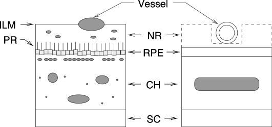
The eye fundus has a multilayer structure, with each layer having its own wavelength-dependent absorption and scattering properties. The structures of interest are retina vessels, the retinal pigmented epithelium (RPE), the choroid (CH), and the sclera (SC). Figure 1 illustrates the layout of the ocular fundus along with the model used for the eye phantom. Veins, arteries, and capillaries are the observable vessels in the retina (as large as 250 μm in diameter for veins, 150 μm for arteries, and 10 μm for capillaries). The vessels are strongly absorbing in the visible range of the spectrum due to hemoglobin, as well as highly scattering due to the presence of erythrocytes. The vessels are surrounded by a 250-μm-thick layer called the neural retina (NR) that includes the photoreceptors (PR). The next layer is the RPE, a one-cell layer filled with melanin approximately 10 μm thick. The choroid is a spongy layer of interlaced fibers interwoven with both large and small blood vessels and capillaries; it is approximately 250 μm thick. Finally, the sclera (SC) is a 700-μm-thick layer composed of collagen fibrils (type I and type III). The sclera is highly scattering and exerts little absorption. Our model for the eye phantom neglects the neural retina since it is a low-absorbing23 and a low-scattering layer compared to the RPE and the CH. Accordingly, the eye phantom includes a retinal vessel and three layers: the SC, the CH, and the RPE.
Figure 1.
Simplified version of the ocular fundus (left) and the model used for the eye phantom (right). Retinal vessel diameters are within 10 and 250 μm. The layer starting with the inner limiting membrane (ILM) and ending with the photoreceptor (PR) is the neural retina (NR). The retinal pigmented epithelium (RPE) is a 10-μm-thick layer. The main absorber in this layer is the melanin. The choroid (CH) is a complex 250-μm-thick structure comprising large blood vessels, melanocytes, and connective tissues including collagen. The sclera (SC) is a 700-μm-thick layer composed of collagen fibrils.
Since our phantom layers are thicker than the corresponding layers in the real eye, their optical properties were scaled to obtain similar optical thicknesses. We refer here to optical properties of human and cow eyes as they have been documented by Hammer et al.24 and Preece and Claridge.9 The product was scaled to match Hammer’s values.
Eye Phantom
Description
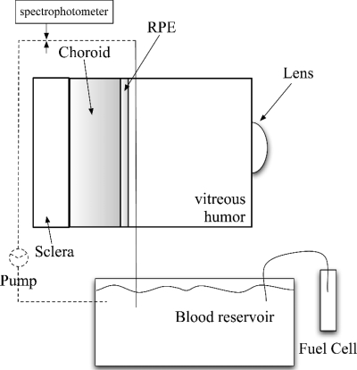
The main elements of our eye phantom are shown in Fig. 2. A mechanical housing made of black Delrin® (width=5 cm, height=5 cm, and depth=3 cm) was constructed to simulate the eyeball. The pupil diameter of the model eye was set to 6 mm with a small hole drilled in the front of the mechanical housing. A planoconvex lens (f=17 mm, Rolyn Optics, Coviana, California) was positioned in front of the pupil to mimic the crystalline lens. A microtube with an inner diameter of 150 μm was used as a retinal blood vessel (index of refraction of the tube: n=1.34). A micropump (Bio-Chem Fluidics Inc., Boonton, New Jersey) was used to pump blood through the vessel delivering 34 μl∕min. The microtube, the pump, and a blood reservoir were connected in a closed circulatory system. The experiment was performed with both human or cow hemoglobin (Sigma Co., St. Louis, Missouri), although data collected with cow hemoglobin are presented in the results section. Changes in oxygen saturation in the capillary tube representing the retinal vessels are desirable to test the reliability of oximetry models and to calibrate a retinal oximeter.8 Therefore, a reversible fuel cell (Horizon Fuel Cell Tech, Shanghai, China) was used to create the oxygen supply to the system. A reversible fuel cell uses water and electricity to produce oxygen and hydrogen gas. Oxygen from the fuel cell was redirected into a blood reservoir to reoxygenate originally fully deoxygenated blood. Initial total deoxygenation was achieved by adding sodium hydrosulfide (Fisher Scientific, Pittsburgh, Pennsylvania) to the blood reservoir that was sealed to avoid air contamination. A tungsten halogen lamp and a spectrophotometer (Ocean Optics, Dunedin, Florida) were connected on either side of the capillary tube via two fiber optics (200 μm core) to obtain real-time values of oxygen saturation of the recirculating blood.
Figure 2.
The dynamic eye phantom realization. A planoconvex lens (f=17 mm) mimics the crystalline lens. A microtube (inner diameter=150 μm, index of refraction of the tube n=1.34) represents a retinal blood vessel. A reversible fuel cell supplies oxygen to a mixture of hemoglobin and water. The oxygen saturation of the recirculating hemoglobin is estimated by spectroscopic measurements. The background layers of the eye phantom are the RPE, the CH, and the SC.
Fabrication
The fundus phantom is composed of two background layers, i.e., the RPE and the CH, plus the SC. The RPE and the CH phantoms were designed as square-shaped solid plastic materials (width=35 mm and height=40 mm). These phantom layers were cast in different Teflon® molds. Two types of design were chosen for the choroid phantom. First, a set of three stackable 2-mm-thick slabs was considered. Hence, the corresponding mold was machined to obtain a 2-mm-thick flat layer. To more closely mimic the spongy structure of the choroid, a second design was proposed: The choroid phantom was then designed as a tank to be filled with fully oxygenated hemoglobin. Accordingly, the CH phantom was composed of two tank walls glued together. Each tank wall was cast in 2-mm-thick molds with a central 1-mm-thick insert; the resulting tank was 2 mm thick with 2-mm-thick walls. The RPE phantom mold was machined to obtain a 1-mm-thick flat layer.
Construction of the phantom layers requires three components: the casting material, the absorbing chromophores, and the scattering agent. Following Moffitt et al.,11 selection of the component was driven by our choice of absorbing dyes. We used a waterproof ink (Black Magic Ink, Higgins, Bellwood, Illinois) as the absorber. It has a flat absorption spectrum on the region of interest,18 i.e., 450 to 800 nm. Madsen et al.25 showed that molecular ink can not be considered as a pure absorber, since it is composed of ink particles of different sizes that can exhibit scattering properties. However, small ink particles have proven to have a small scattering efficiency and a high absorption component. Hence, a stock solution of ink plus purified water was prepared and sonicated to break the longer aggregates. We assumed that this solution was mostly absorbing. Commonly used scattering agents are TiO2, Al2O3, and calibrated microspheres. We used TiO2 as the scatterer. Moreover, both ink and TiO2 present greater stability in solids. We considered three casting materials: polyurethane, casting resin, and epoxy. Polyurethane mixes homogeneously with most materials, but takes 24 h to harden and requires degassing in a vacuum chamber. Casting resin hardens quickly but has a shorter shelf life (a yellow color develops within a few hours), must be degassed in a vacuum chamber, and does not mix homogeneously with materials. Epoxy (Enviro Tex Lite) mixes homogeneously with materials and can be degassed with CO2, but takes 24 h to harden. Since epoxy is simple to operate and easy to mold, and gives long-lasting phantoms, this material was used as the bulk material of our phantom layers.
Preparation of phantom layers started by weighing the desired amount of TiO2 powder and mixing it with 1 ml of deionized water. This mixture was placed in an ultrasonic bath for 5 min to break the aggregates. Next, we added 10 cm3 of epoxy resin and mixed until visibly homogenous. We added the required volume of a sonicated ink plus purified water stock solution in our resin mixture and again mixed it until we achieved visible homogeneity. Finally, 10 cm3 of epoxy hardener was added and mixed for 2 min. The mixture was poured into Teflon® molds and degassed with CO2. Once cured, each phantom was slightly sanded to prevent specular reflection (wet sandpaper, grit size 3 μm). Building phantoms was a long process requiring many trials and errors to achieve the desired optical properties. Bubbles remaining in the casting material, sedimentation in the TiO2 batch, and possible conglomerates of the ink are to be cited as typical problems. Since RPE contains melanin, a strong light absorber, note that this layer was considered only an absorbing layer, i.e., no scatterers were added to the composition of the RPE phantoms. However, scattering properties due to ink were measured for these phantoms. A 0.4-cm-thick Spectralon standard slab was attached to the back of the mechanical housing to represent the SC as a highly scattering layer. The housing was filled with purified water to represent the vitreous humor.
Measurements of Phantom Optical Properties
An integrating sphere and IAD (Ref. 22) were used to estimate the optical properties of the phantom layers. With the IAD method, the radiative transport equation is iteratively solved until the calculated total reflection and transmission match the measured values. It is an entirely numerical method in which the optical properties of the sample are calculated from the reflection and transmission values. The optical parameters are then the absorption coefficient μa, the scattering coefficient μs, and the scattering anisotropy parameter (mean cosine of the angle of scattering from the incident direction of light). Hence, the assessment of these parameters requires three measurements: the total reflection, the total transmission, and the unscattered transmission. In our case, only the measured total reflection and the measured total transmission were available to our measuring method and the IAD computed μa and [the reduced scattering coefficient, ]. However, g can be calculated from Rayleigh or Mie theory, provided that the scatterer particle type and size is known26, 27 or estimated by goniometric measurements. Hence, one can estimate μs from estimates of and g.
All measurements were obtained with an integrating sphere (Labsphere, 10.2 cm diameter, calibrated wall reflectance of 97.1%) and a tungsten halogen lamp connected by a fiber optic to a spectrophotometer (Ocean Optics, Dunedin, Florida). The IAD program requires total reflectance and transmittance measurements as inputs. In each experimental situation, i.e., reflection and transmission, three intensities were measured and the total diffuse reflection and the total diffuse transmission were computed following Eq. 1:
| (1) |
where superscripts R and T, respectively, stand for reflection and transmission measurements; and Isample, Istandard, and Idark are the light intensities measured for the sample, on a 99% reflectance spectralon standard (certified by The National Institute of Standards and Technology) and without any target, respectively. The details on how to make these optical property measurements with an integrating sphere can be found elsewhere.11 The IAD method was then used to calculate μa and .
Results
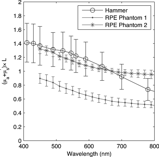
Results for two RPE phantoms are presented Fig. 3. We repeated the reflection measurements and the transmission measurements five times for each phantom to ensure measurement validity. The RPE phantoms were designed to match results obtained by Hammer for a 10-μm-thick RPE with an anisotropy coefficient g=0.84 for all wavelengths.24 Figure 3 presents the computation of versus wavelength and shows that our two RPE phantom values are close to Hammer’s values.
Figure 3.
Computation of versus wavelength for two RPE phantoms compared to Hammer’s values24 for a 10-μm-thick RPE.
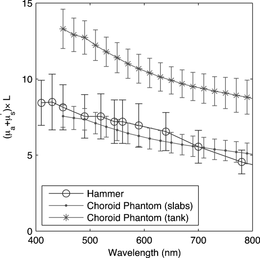
Results for two CH designs are presented Fig. 4. The type 1 CH design corresponds to a stack of three slabs, whereas in the type 2 design, the CH is a tank filled with a mix of ink, TiO2, and water. The reflection and transmission measurements required by IAD computation were performed five times on each slab as well as on the CH tank wall and the filling ink-TiO2-water mix. Ultimately, the tank could be filled with blood or hemoglobin to better simulate the choroidal structure. Figure 4 presents the computation of versus wavelength for type 1 (slabs) and type 2 (tanks) CH designs. Our experimental data show that our CH phantoms encompass Hammer’s values. Notes however, that Hammer’s assumption of a wavelength-independent anisotropy coefficient is very unlikely as biological media tend to have a wavelength-dependent g coefficient.
Figure 4.
Computation of versus wavelength for two CH phantoms compared to Hammer values24 for a 250-μm-thick bloodless CH.
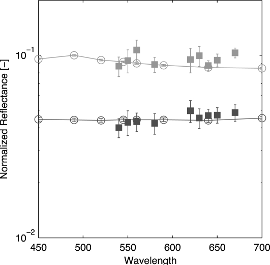
We measured the reflectance of the fundus phantom with a newer version of our retinal oximeter28 and compared the results to Monte Carlo simulations of a combined RPE and CH phantom. The absorption and scattering coefficients used in the simulations are illustrated in Fig. 34. All simulations were conducted with Monte Carlo for multi-layered media29 (MCML) and 1 million photons. An incident pencil beam was set at eight different wavelengths, distributed between 450 and 700 nm. MCML is an ideal program for this type of simulation because of its ability to model light transport into layered structures. We used the average values μa=⟨μa⟩ and μs=⟨μs⟩ resulting from IAD computations for both the CH slabs and the RPE. As suggested by Moffitt et al.,11 a scattering anisotropy of g=0.5 for TiO2 was used for these simulations. Measurement of the reflectance of the eye phantom was made with our retinal oximeter setup, which provides nine wavelength-dependent images of the fundus in a snapshot (λ=540,550,560,580,610,630,640,650,670 nm). We conducted the measurements with the type-1-design CH (slabs). We also used the whole set of RPEs. Hence, two reflectance curves were calculated using
| (2) |
where A is a scaling factor accounting for the setup apparatus. The intensity reflected from the eye phantom Iphantom is normalized by the intensity reflected from the SC Isclera. A dark image was also captured by keeping the light source off. This image was subtracted from every image. The results presented in Fig. 5 show that the measured reflectance is close to the simulated reflectance resulting from the Monte Carlo simulations.
Figure 5.
Reflectance measurement issued of nine wavelength-dependent snapshot images (filled symbols) and comparison to Monte Carlo simulations (lines). The fundus phantom was a two-layer model composed of the RPE and the type-1-design CH slabs (light symbols, RPE phantom 1; dark symbols, RPE phantom 2).
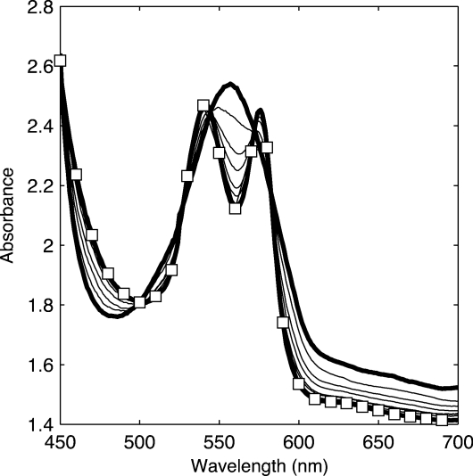
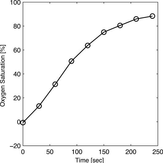
The reliability of the incoming oxygen control was estimated by absorption spectrometric measurements on bovine hemoglobin circulated in the vessel phantom. This measurement did not involve the eye fundus phantom, but only the vessel. Although this experiment does not use the retinal oximeter, the same experiment for oxygen saturation estimations using a former version of the retinal oximeter can be found elsewhere.30 However, in this former experiment, no eye fundus phantoms were used and the vessel phantom was set in front of the Spectralon slab mimicking the SC. The blood reservoir was filled with a mixture of 0.1 g bovine hemoglobin combined with 100 ml of water. The reoxygenated blood absorption was measured using a spectrophotometer and 30-s intervals. Figure 6 shows initially a classic deoxygenation curve as the thick line curve with one maximum around 560 nm. Over time, there is a noticeable transition to the classic two-maxima oxygenated Hb curves (thick line with squares). Once it was shown that a gradual reoxygenation of the blood over time could occur, the oxygen saturation was computed using the equation from Delori,5 and the results are shown in Fig. 7. This figure shows that oxygen saturation increases with the introduction of oxygen.
Figure 6.
Absorption spectrum of reoxygenated cow hemoglobin. The thick line corresponds to fully deoxygenated hemoglobin measurements, whereas the line with squares corresponds to 90% oxygenated hemoglobin measurements.
Figure 7.
Oxygen saturation of reoxygenated hemoglobin computed with Delori’s equation.5
Conclusions
We presented the construction of an optical model of the eye, composed of a retinal vessel and three layers: the RPE, the CH, and the SC Epoxy was used as the main phantom material since it gives long-lasting phantoms and can be easily constructed. The absorbing agent was a waterproof ink and the scattering agent was TiO2. The RPE and CH layers were considerably thicker than their eye counterparts, but the optical thicknesses of the phantom layers were matched to the optical thicknesses of each layer. Phantom optical properties were measured with an integrating sphere and the IAD model. Interchangeable phantoms with different optical properties were constructed for the RPE and the CH. The oxygen content of the hemoglobin circulating in the mock vessel could be dynamically controlled by using an inverted fuel cell that generates oxygen. Oxygen saturation was then estimated with spectrometric measurements.
Note that the CH layer in our eye model did not capture the spongy structure of a real CH. Moreover, we used a mixture of water and hemoglobin instead of blood in our phantom. Hence, the scattering properties of red blood cells were neglected. Ultimately, the ideal solution would be to circulate real blood.
This eye phantom was designed for total diffused reflectance measurements. Our Monte Carlo simulations of the diffuse reflectance were compared to actual reflectance measurements, showing the validity of the eye phantom. Owing to the thicknesses of the various layers, this phantom could not be used for other structure-dependent measures such as optical coherence tomography (OCT) or confocal microscopy. However, our group is currently working on an optical phantom that mimics the optical properties and the actual thicknesses of the eye layers that could be used for such measurements.
Acknowledgments
The authors thank A. Nabili, D. Bardakci, K. Helling, C. Matyas, and S. Muro for their collaboration in making the phantom and D. Smolley for technical assistance in achieving the mechanical items. We are grateful for the support from the Coulter Foundation and the National Institutes of Health (NIH) Grant No. EY017577-01A11.
References
- Nguyen Q. D., Shah S. M., Anden E. V., Sung J. U., Vitale S., and Campochiaro P. A., “Supplemental oxygen improves diabetic macular edema: A pilot study,” Invest. Ophthalmol. Visual Sci. 45, 617–624 (2004). 10.1167/iovs.03-0557 [DOI] [PubMed] [Google Scholar]
- Wangsa-Wirawan N. D. and Linsenmeier R. A., “Retinal oxygen: Fundamental and clinical aspects,” Arch. Ophthalmol. (Chicago) 121, 547–557 (2003). [DOI] [PubMed] [Google Scholar]
- Hickam J. B., Frayser R., and Ross J. C., “A study of retinal venous blood oxygen saturation in human subjects by photographic means,” Circulation 27, 375–385 (1963). [DOI] [PubMed] [Google Scholar]
- Hickam J. B. and Frayser R., “Studies of the retinal circulation in man: Observations on vessel diameter, arteriovenous oxygen difference, and mean circulation time,” Circulation 33, 302–316 (1966). [DOI] [PubMed] [Google Scholar]
- Delori F. C., “Noninvasive technique for oximetry of blood in retinal vessels,” Appl. Opt. 27, 1113–1125 (1988). 10.1364/AO.27.001113 [DOI] [PubMed] [Google Scholar]
- Delori F. C. and Pflibsen K. P., “Spectral reflectance of the human ocular fundus,” Appl. Opt. 28, 1061–1077 (1989). 10.1364/AO.28.001061 [DOI] [PubMed] [Google Scholar]
- Schweitzer D., Leistritz L., Hammer M., Bartsch U., and Srobel J., “Calibration-free measurement of he oxygen saturation in retina vessels of men,” Proc. SPIE 2393, 210–218 (1995). 10.1117/12.209850 [DOI] [Google Scholar]
- Ramella-Roman J. C. and Mathews S. A., “Spectroscopic measurements of oxygen saturation in the retina,” IEEE J. Sel. Top. Quantum Electron. 13, 1697–1703 (2007). 10.1109/JSTQE.2007.911312 [DOI] [Google Scholar]
- Preece S. J. and Claridge E., “Monte carlo modelling of the spectral reflectance of the human eye,” Phys. Med. Biol. 47, 2863–2877 (2002). 10.1088/0031-9155/47/16/303 [DOI] [PubMed] [Google Scholar]
- Bargo P. R., Prahl S. A., and Jacques S. L., “Optical properties effects upon the collection efficiency of optical fibers in different probe configurations,” IEEE J. Sel. Top. Quantum Electron. 9, 314–321 (2003). 10.1109/JSTQE.2003.811287 [DOI] [Google Scholar]
- Moffitt T., Chen Y.-C., and Prahl S. A., “Preparation and characterization of polyurethane optical phantoms,” J. Biomed. Opt. 11, 041103 (2006). 10.1117/1.2240972 [DOI] [PubMed] [Google Scholar]
- Bargo P. R., Prahl S. A., and Jacques S. L., “Collection efficiency of a single optical fiber in turbid media,” Appl. Opt. 42, 3187–3197 (2003). 10.1364/AO.42.003187 [DOI] [PubMed] [Google Scholar]
- Linford J., Shalev S., Bews J., Brown R., and Schipper H., “Development of a tissue-equivalent phantom for diaphanography,” Med. Phys. 13, 869–875 (1986). 10.1118/1.595948 [DOI] [PubMed] [Google Scholar]
- McDonald M., Lochhead S., Chopra R., and Bronskill M. J., “Multi-modality tissue-mimicking phantom for thermal therapy,” Phys. Med. Biol. 49, 2767–2778 (2004). 10.1088/0031-9155/49/13/001 [DOI] [PubMed] [Google Scholar]
- Durkin A., Jaikumar S., and Richards-Kortum R., “Optically dilute, absorbing, and turbid phantoms for fluorescence spectroscopy of homogeneous and inhomogeneous samples,” Appl. Spectrosc. 47, 2114–2121 (1993). 10.1366/0003702934066244 [DOI] [Google Scholar]
- Hebden J. C., Veenstra H., Dehghani H., Hillman E. M. C., Schweiger M., Arridge S. R., and Delpy D. T., “Three-dimensional time-resolved optical tomography of a conical breast phantom,” Appl. Opt. 40, 3278–3287 (2001). 10.1364/AO.40.003278 [DOI] [PubMed] [Google Scholar]
- Firbank M. and Delpy D. T., “A phantom for the testing and calibration of near infrared spectrometers,” Phys. Med. Biol. 39, 1509–1513 (1994). 10.1088/0031-9155/39/9/015 [DOI] [PubMed] [Google Scholar]
- Pogue B. W. and Patterson M. S., “Review of tissue simulating phantoms for optical spectroscopy, imaging and dosimetry,” J. Biomed. Opt. 11, 041102 (2006). 10.1117/1.2335429 [DOI] [PubMed] [Google Scholar]
- Denninghoff K. R. and Smith M. H., “Optical model of the blood in large retinal vessels,” J. Biomed. Opt. 5, 371–374 (2000). 10.1117/1.1289144 [DOI] [PubMed] [Google Scholar]
- McNaught A., Mordant D., Alabboud I., Ritchie P., Muyo G., and Harvey A., “Development of a model eye to validate oximetric measurements in the human retinal vasculature using hyperspectral imaging,” in Proc. Assoc. Res. Vis. Ophthalmol. Annu. Meeting (2008).
- Drewes J. J., “Four-wavelength retinal vessel oximetry,” PhD thesis, University of Alabama Huntsville (1999). [Google Scholar]
- Prahl S. A., “The adding-doubling method,” in Optical-Thermal Response of Laser Irradiated Tissue, Welch and van Gemert M. J. C. Eds., Chap. 5, pp. 101–129, Plenum Press, New York (1995). [Google Scholar]
- Hammer M. and Schweitzer D., “Quantitative reflection spectroscopy at the human ocular fundus,” Phys. Med. Biol. 47, 179–191 (2002). 10.1088/0031-9155/47/2/301 [DOI] [PubMed] [Google Scholar]
- Hammer M., Roggan A., Schweitzer D., and Müller G., “Optical properties of ocular fundus tissues-an in vitro study using the double-integrating-sphere technique and inverse Monte Carlo simulation,” Phys. Med. Biol. 40, 963–978 (1995). 10.1088/0031-9155/40/6/001 [DOI] [PubMed] [Google Scholar]
- Madsen S. J., Patterson B. C., and Wilson M. S., “The use of india ink as an optical absorber in tissue-simulating phantoms,” Phys. Med. Biol. 37, 985–993 (1992). 10.1088/0031-9155/37/4/012 [DOI] [PubMed] [Google Scholar]
- Van de Hulst H. C., Light Scattering by Small Particles, Dover, New York: (1981). [Google Scholar]
- Bohren C. F. and Huffman D. R., Absorption and Scattering of Light by Small Particles, Wiley, New York: (1983). [Google Scholar]
- Lemaillet P., Lompado A., and Ramella-Roman J. C., “Improvement of a snapshot spectroscopic retinal multi-aperture imaging camera,” in Medical Imaging 2009 Biomedical Applications in Molecular, Structural and Functional Imaging, Proc. SPIE 7262, 72622G (2009). 10.1117/12.811565 [DOI] [Google Scholar]
- Wang L., Jacques S. L., and Zheng L., “MCML Monte Carlo modeling of light transport in multi-layered tissues,” Comput. Methods Programs Biomed. 47, 131–146 (1995). 10.1016/0169-2607(95)01640-F [DOI] [PubMed] [Google Scholar]
- Ramella-Roman J. C., Mathews S. A., Kandimalla H., Nabili A., Duncan D. D., D’Anna S. A., Shah S. M., and Nguyen Q. D., “Measurement of oxygen saturation in the retina with a spectroscopic sensitive multi aperture camera,” Opt. Express 16, 6170–6182 (2008). 10.1364/OE.16.006170 [DOI] [PubMed] [Google Scholar]


