Abstract
This letter reports the development of an optofluidic Fabry–Pérot (FP) resonator, which consists of a microcavity and a pair of liquid microlenses. The microcavity forms part of the microchannel to facilitate sample injection. The liquid microlenses are used for efficient light coupling from the optical fiber to the microcavity. The liquid microlens collimates the diverging light from the optical fiber into the FP cavity, which provides real-time tuning to obtain the highest possible finesse up to 18.79. In volume refractive index measurement, a sensitivity of 960 nm per refractive index unit (RIU) and a detection range of 0.043 RIU are achieved.
INTRODUCTION
Recently, volume refractive index (RI) measurement in microfluidic systems has gained attention from researchers to explore and develop the measurement techniques for better sensitivity and higher resolution, such as fiber-based Fabry–Pérot (FP) resonator,1 Fiber–Bragg-grating (FBG) interferometer,2, 3 and Bragg reflector type resonator.4 All these devices use the change in optical path length in the cavity when light propagates through different samples to determine the RI of the sample. Based on the measured RI value, researchers can determine the concentration of solute in a solution or study the relation of living cell’s RI with the cell permeability, cell viability, or hematology.5, 6, 7 Among these techniques, FP resonator has the advantages of simplicity as compared to FBG, which requires complex grating writing process, and Bragg reflector, which requires deep reactive ion etching.
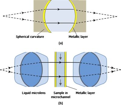
In the FP resonator, a pair of optical fibers with gold-coated facets is aligned and separated by a microchannel that acted as the resonant cavity. Ideally, the light should be effectively trapped in the cavity, i.e., parallel light beam in a perfectly aligned planar cavity. However, light that emerged from an optical fiber is diverging and induces optical loss in the FP resonator, which limits the finesse of the FP resonator, i.e., about 5 as reported in Ref. 1. In order to improve the optical quality of the resonator, light collimation mechanism has to be included. Light collimation for optical fiber has been demonstrated using graded index fiber end,2 hollow-core waveguide,8 or epoxy microlens.9 However, using graded index fiber end for collimation not only makes the control of the length for full collimation difficult but also reduces the measurement range as the cavity length is increased. Inserting hollow-core waveguide is costly and difficult in integration. Epoxy microlens is more suitable for single chip integration. However, it lacks flexibility in fabricating the desired microlens as it is not easy to control the curvature and the height of the microlens. In addition, with the fiber facets which acted as resonator, fiber misalignment and poor facet quality degrade the finesse or the quality factor of the resonator. To provide better light manipulation and confinement, spherical FP resonator, which is less sensitive to geometrical misalignment, is a better and more stable configuration, as shown in Fig. 1a. The spherical curvatures provide two functions, i.e., diverging light is collimated by the spherical curvature and collimated light is confined to undergo resonance between the highly reflective spherical surfaces.
Figure 1.
Schematic illustrations of (a) the physics model of spherical FP resonator that consists of a pair of spherical curvature coated with highly reflective metallic layer and (b) optofluidic FP resonator with a pair of liquid microlenses for light confinement.
Optofluidics is the class of optical system that is synthesized with fluids to provide unique optical properties, such as real-time tunability, optically smooth interface, compact, and easy integration.10 These optical properties cannot be achieved using solid-state components. Different optical components have been developed, such as optical waveguide,11 optical filter,12 fluidic microlenses,13, 14 etc. In this letter, an optofluidic FP resonator uses a pair of highly optical performing liquid microlenses to provide the function of light collimation with real-time tunability, as shown in Fig. 1b. A gold-coated microchannel between the liquid microlenses provides the function of light resonance and also sample manipulation. The microchannel is prealigned during fabrication to avoid losses due to geometrical misalignment. The optofluidic FP resonator separates light collimation from the resonant cavity, which provides greater flexibility in the design of sample manipulation for measurement.
DESIGN AND FABRICATION
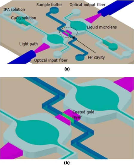
Figure 2a shows the schematic of the optofluidic FP resonator, which consists of a pair of expansion chambers with two inlets for liquid microlens formation, a central microchannel as the FP cavity, and a pair of optical fiber for optical input and output. The liquid microlens is formed in the expansion chamber with 250 μm width using three laminar flows.13, 14 The curvatures of the microlenses can be easily tuned by controlling the ratio of the flow rates to improve the optical coupling efficiency. The sidewalls of the central microchannel are coated with gold layer to increase the reflectance, which is critical for high-finesse resonator, as shown in Fig. 2b. The microchannel, which is 15 μm, is prealigned during fabrication to avoid losses due to geometrical misalignment. For RI measurement, the sample is injected into the microchannel and the transmission resonant spectrum is recorded.
Figure 2.
Schematic illustrations of (a) the optofluidic FP resonator and (b) the microcavity with gold-coated sidewalls.
The liquid microlens is formed in the expansion chamber with the central and the side flow streams injected with 4.16 mol l−1 CaCl2 solution (RI=1.4621) and isopropyl alcohol solution (RI=1.3802). The diffusion at the liquid interfaces due to the concentration difference between the two liquid layers is minimized because the diffusion distance of Ca2+ and Cl− ions is reduced when the flow rate is very fast.14 Therefore, the diffusive broadening of the interfaces is eliminated and the microlenses formed have a better match with the ideal lens. In addition, the liquid microlenses have optically smooth curvatures, which ensure high quality light manipulation and collimation. The expansion chamber has an aspect ratio of 1: 1 and an injection angle of 70° to minimize the deviation of the lens curvature from the ideal lens shape and also to avoid the formation of recirculation zones in the expansion chamber, which will cause instability.14 As the RI of the central flow stream is higher than that of the side flow streams, biconvex converging microlenses with different radii of curvature (r) can be formed by tuning the ratio of the flow rates between the central and the side flow streams. The distance between the fiber facet and the center of the expansion chamber is 1 mm.
The chip is fabricated in polydimethylsiloxane (PDMS) material using soft lithography process. The mold is fabricated using SU-8 50 on a silicon wafer. On the PDMS chip, the sidewalls of the central microchannel are coated with about 40 nm gold layer using the sputtering system. The patterned PDMS slab is bonded to the other PDMS slab using plasma bonding. PDMS with a RI of 1.412 is transparent in visible and infrared wavelengths that meets the design criteria of optofluidic chips. In the characterization of the optofluidic FP resonator, a superluminescence light emitting diode (SLED) with a central wavelength of 1275 nm and a bandwidth of 70 nm is used. The transmission spectrum is detected using the optical spectrum analyzer with a resolution of 0.01 nm. All liquids are injected into the chip using syringe pumps. In order to visualize the light path, fluorescein dyes are introduced into the liquid flows. The SLED is replaced with the argon ion laser with an output wavelength of 488 nm for the fluorescent excitation. In RI measurement, certified RI liquids (series AA, Cargille Laboratories, USA) with RI ranging from 1.493 to 1.528 are used. The RI liquids have low temperature dependence (0.0004 °C−1) to avoid measurement error due to the surrounding temperature.
RESULTS AND DISCUSSIONS
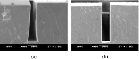
In order to realize a high-finesse FP cavity, several issues need to be investigated, i.e., the parallelism between the sidewalls and the surface roughness of the sidewalls. Figure 3 shows the scanning electron microscope photographs of the FP cavity in the cross-sectional view. Low finesse resonator is formed if the two sidewalls are slanted and not in parallel, as shown in Fig. 3a. For high-finesse resonator, the PDMS sidewalls are in parallel and the imperfection is measured to be smaller than 0.1°, as shown in Fig. 3b. Vertical PDMS sidewalls can be obtained using SU-8 master mold. SU-8 can ensure uniform exposure conditions in the near-UV range and produce structures with highly vertical sidewalls and smooth features.15 The surface roughness of the sidewalls is measured to be less than 100 nm. Therefore, the surface roughness has negligible effect on the finesse of the FP cavity.
Figure 3.
SEM micrographs of (a) unparallel FP cavity and (b) parallel FP cavity.
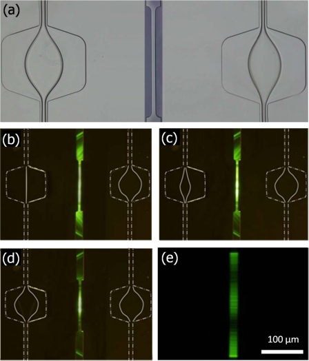
The collimation efficiency with respect to the radius of curvature (r) of the microlenses is shown in Fig. 4. The liquid microlenses are shown in Fig. 4a. The radii of curvature of the liquid microlenses are tuned by changing the flow rate of the core flow stream. Without the formation of the liquid microlens, only a small portion of the light (parallel light at the central beam) undergoes resonance within the FP cavity and diverging light is observed outside the FP cavity in the microchannel, as shown in Fig. 4b. However, when the liquid microlens of r=150 μm is formed, it can be seen that more light is collimated and undergoes resonance, as shown in Fig. 4c. Less diverging light is observed outside the FP cavity in the microchannel. The light that emerged from the optical fiber is fully collimated when a liquid microlens of r=138 μm is formed, as shown in Fig. 4d. It can be clearly seen that most light is collimated and undergoes resonance in the FP cavity and nearly negligible diverging light is observed outside the FP cavity in the microchannel. The light beam in the FP cavity is collimated when observed using a 40× objective lens, as shown in Fig. 4e.
Figure 4.
(a) Microphotograph of the formation of liquid microlenses in the expansion chambers. Optical micrographs of the light beam when (b) no microlens, (c) microlens with r=150 μm, and (d) microlens with r=138 μm is formed. Zoom view of the collimated beam in the cavity that is captured using a 40× objective lens.
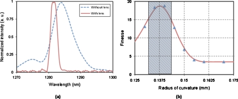
Figure 5a shows the quality of the FP cavity without and with liquid microlenses. The free spectral range (FSR) of the FP resonator is 40.21 nm. With the full width half maximum (FWHM) of 11.55 nm, the finesse (FSR∕FWHM) of the FP cavity without liquid microlenses is 3.48. The finesse of the FP cavity is greatly improved from 3.48 to 18.79 when liquid microlenses with r=138 μm are formed. At this condition, most of the light is collimated, undergoes resonance, and efficiently couples back to the detection fiber. As the highest finesse is achieved when liquid microlenses with r=138 μm are formed, it can be deduced that the light is collimated in the FP cavity. When the radius of the curvature of the liquid microlenses is further reduced, the light from the optical fiber is converged. Converging light is inefficient in undergoing resonance. Therefore, the FP cavity becomes lossier and the finesse is reduced, as shown in Fig. 5b. The finesse of the FP cavity is greatly improved as compared to the previous reported FP resonators in microfluidic systems, which are 5–7.1, 4
Figure 5.
(a) The transmission spectra of the optofluidic FP resonator without microlenses and with microlenses (r=138 μm). (b) The finesse of the resonant cavity vs the radius of curvature of the microlenses.
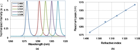
Figure 6a shows the output transmission spectra when the RI liquids are injected into the microcavity. Using the de-ionized water (RI=1.321 in 24 °C) as the reference, the refractive indices of the RI liquids are measured. The relation between the resonant peak and the RI of the sample liquid in the microcavity is shown in Fig. 6b. The sensitivity of the FP resonator is measured as 960 nm∕refractive index unit (RIU), which is in good agreement with the theoretical calculated result based on the perturbation method.16 The detection range is measured to be 0.043 RIU. The detection limit (FWHM∕sensitivity) is estimated to be 0.01, which can be improved by further increasing the finesse of the cavity. However, ultimately it will be limited by the damping in the liquid flow when the quality of cavity confinement becomes sufficiently high.17
Figure 6.
(a) The transmission spectra of the buffer solutions with different refractive indices. (b) The shift of the resonant peak as a function of the RI of the buffer solution.
In order to show the importance of achieving a higher finesse FP cavity, the precision of the measurement is investigated using different finesses of the FP cavity. In the experiment, 30 output spectra are captured in each cases and a peak is located. The standard deviation and standard error are calculated based on the 30 output spectra. A low finesse cavity of 3.48 has a standard deviation of 0.0228 and a standard error of 0.0046, as shown in Table 1. When a high-finesse cavity is used, the standard deviation and standard error are reduced to 0.0027 and 0.0008, respectively. The standard deviation achieved is improved as compared with previous devices.1, 3, 4 Based on the experimental results, the precision of the measurement is increased by employing a high-finesse cavity.
Table 1.
Precision of peak localization.
| Finesse | 3.48 | 18.79 |
|---|---|---|
| Standard deviation | 0.0228 | 0.0027 |
| Standard error | 0.0046 | 0.0008 |
The developed optofluidic FP resonator provides several advantages as compared to previous techniques. First, the finesse of the FP resonator is greatly improved by collimating the diverging beam emerged from the fiber. Second, the liquid microlenses are optically smooth to reduce light scattering or propagation loss. The diffusion broadening effect of the interfaces can be reduced using higher flow rates.14 Third, the cavity length is not limited by the resonator as found in the Bragg reflector type resonator.5 Smaller cavity length is preferred to have a larger detection range. Fourth, as the FP cavity is not formed by the fibers, the alignment of the fibers has less effect on the finesse of the resonator. In addition, the fiber grooves are prealigned in the design and the fabrication of the microfluidic chip. The alignment of the fibers with the liquid microlenses and the FP cavity is relatively easy.
The liquid microlenses provide collimation along the plane of the microchannels, which cannot avoid the diffraction loss in the plane perpendicular to the plane of the microchannels (vertical plane). To improve the light collimation in the vertical plane, three-dimensional liquid microlenses can be employed to reduce the diffraction loss. The finesse of the FP resonator is expected to be further improved.
CONCLUSIONS
In conclusion, an optofluidic FP resonator is designed, fabricated, and demonstrated. A pair of liquid microlenses is integrated onto the FP cavity. It is a simple way to realize a real-time tunable FP resonator such that light is manipulated easily using liquid microlenses and confined in the FP cavity. The collimated light propagation enhances the finesse and reduces the loss of the FP resonator. In the optofluidic FP resonator, the resonant cavity is formed in the central microchannel with the sidewalls coated with gold layers. The gold layers increase the reflectance of the sidewalls and subsequently the finesse of the FP cavity. By tuning the radii of the curvature of the liquid microlenses, the finesse of the FP cavity can be enhanced by 5.4 times, i.e., 18.79. The optofluidic FP resonator has a measuring range of 0.043 RIU and a detection sensitivity of 960 nm∕RIU for buffer solution measurement. The optofluidic FP resonator has the advantages of real-time monitoring, high precision, low cost, simple fabrication, and single chip integration. It has high potential for single cell measurement.
ACKNOWLEDGMENTS
This work was supported by the Environmental and Water Industry Development Council of Singapore (Grant No. MEWR C651∕06∕171).
References
- Song W. Z., Zhang X. M., Liu A. Q., Lim C. S., Yap P. H., and Hosseini H. M., Appl. Phys. Lett. 89, 203901 (2006). 10.1063/1.2387965 [DOI] [Google Scholar]
- Domachuk P., Littler I., Cronin-Golomb M., and Eggleton B., Appl. Phys. Lett. 88, 093513 (2006). 10.1063/1.2181204 [DOI] [Google Scholar]
- Chin L. K., Liu A. Q., Lim C. S., Zhang X. M., Ng J. H., Hao J. Z., and Takahashi S., Appl. Phys. Lett. 91, 243901 (2007). 10.1063/1.2823610 [DOI] [Google Scholar]
- St-Gelais R., Masson J., and Peter Y. A., Appl. Phys. Lett. 94, 243905 (2009). 10.1063/1.3152286 [DOI] [Google Scholar]
- Barer R., Ross K. F. A., and Tkaczy S., Nature (London) 171, 720 (1953). 10.1038/171720a0 [DOI] [PubMed] [Google Scholar]
- Liang X. J., Liu A. Q., Lim C. S., Ayi T. C., and Yap P. H., Sens. Actuators, A 133, 349 (2007). 10.1016/j.sna.2006.06.045 [DOI] [Google Scholar]
- Barer R., J. Opt. Soc. Am. 47, 545 (1957). 10.1364/JOSA.47.000545 [DOI] [PubMed] [Google Scholar]
- Marcuse D. and Stone J., J. Lightwave Technol. 7, 869 (1989). 10.1109/50.19128 [DOI] [Google Scholar]
- Jiang Y. and Tang C., Smart Mater. Struct. 17, 055013 (2008). 10.1088/0964-1726/17/5/055013 [DOI] [Google Scholar]
- Psaltis D., Quake S. R., and Yang C., Nature (London) 442, 381 (2006). 10.1038/nature05060 [DOI] [PubMed] [Google Scholar]
- Wolfe D. B., Conroy R. S., Garstecki P., Mayers B. T., Fischbach M. A., Paul K. E., Prentiss M., and Whitesides G. M., Proc. Natl. Acad. Sci. U.S.A. 101, 12434 (2004). 10.1073/pnas.0404423101 [DOI] [PMC free article] [PubMed] [Google Scholar]
- Levy U., Campbell K., Groisman A., Mookherjea S., and Fainman Y., Appl. Phys. Lett. 88, 111107 (2006). 10.1063/1.2182111 [DOI] [Google Scholar]
- Tang S. K. Y., Stan C. A., and Whitesides G. M., Lab Chip 8, 395 (2008). 10.1039/b717037h [DOI] [PubMed] [Google Scholar]
- Seow Y. C., Liu A. Q., Chin L. K., Li X. C., Huang H. J., Cheng T. H., and Zhou X. Q., Appl. Phys. Lett. 93, 084101 (2008). 10.1063/1.2976210 [DOI] [Google Scholar]
- Natarajan S., Chang-Yen D. A., and Gale B. K., J. Micromech. Microeng. 18, 045021 (2008). 10.1088/0960-1317/18/4/045021 [DOI] [Google Scholar]
- Mortensen N. A., Xiao S., and Pederson J., Microfluid. Nanofluid. 4, 117 (2008). 10.1007/s10404-007-0203-2 [DOI] [Google Scholar]
- Skafte-Pedersen P., Nunes P. S., Xiao S., and Mortensen N. A., Sensors 9, 8382 (2009). 10.3390/s91108382 [DOI] [PMC free article] [PubMed] [Google Scholar]


