

Abstract
Activated Iridium microelectrodes were implanted for 450 to 1282 days in the sensorimotor cortex of 7 adult domestics cats and then pulsed for 240 hours (8 hours per day for 30 days) at 50 Hz. Continuous stimulation at 2 nC/phase and with a geometric charge density of 100 μC/cm2 produced no detectable change in neuronal density in the tissue surrounding the microelectrode tips. However, pulsing with a continuous (100% duty cycle) at 4 nC/ph and with a geometric charge density of 200 μC/cm2 induced loss of cortical neurons over a radius of at least 150 μm from the electrode tips. The same stimulus regimen, but with a duty cycle of 50% (1 sec of stimulation, then 1 second without stimulation repeated for 8 hours) produced neuronal loss within a smaller radius, approximately 60 μm from the center of the electrode tips. However, there also was significant loss of neurons surrounding the unpulsed electrodes, presumably as a result of mechanical injury due to their insertion into and long-term residence in the tissue, and this was responsible for most of the neuronal loss within 150 μm of the electrodes pulsed with the 50% duty cycle.
Keywords: Intracortical microstimulation, Neuronal damage, Neuroprostheses, Sensory prostheses, Cats
Introduction
Microstimulation by penetrating (intraparenchymal) microelectrodes affords better spatial resolution of the electrical stimulus than is possible with stimulating microelectrodes on the surface of the brain (1-3) which may be essential for successful implementation of a cortical-level visual prosthesis (2, 4-7). A neural prosthesis that is safe and effective should activate the requisite population of neurons or axons without causing injury to the neural elements or to other tissue elements. Electrical stimulation excites neurons by inducing a voltage gradient, or a function thereof, across or along the excitable neural elements, as a result of the injection of charge into the tissue. Thus, electrical stimulation is an effective but also an unnatural means of inducing neuronal activity, and appropriate precautions must be observed in order to minimize neuronal injury (8-13). The problem of specifying safe and effective stimulus parameters can be envisioned as determining the boundaries of a multidimensional “therapeutic window” for which the bounds are the threshold for activation of the requisite neural population and the threshold for tissue injury.
There are many application in the basic neurosciences that require microstimulation in the cerebral cortex, and several emerging clinical applications, including sensory feedback for a brain-machine interface (14, 15) and cortical-level visual prostheses (4, 5, 16-18). The feasibility of a visual prosthesis for the blind using intracortical microstimulation of the visual cortex was studied in a 42-year-old woman who had been totally blind for 22 years (4, 5). Thirty-eight microelectrodes were implanted in the right visual cortex, near the occipital pole, for a period of 4 months. Visual percepts described by the subject as small spots of light (phosphenes) were produced with 34 of the 38 implanted microelectrodes. Threshold currents for phosphene percepts induced by trains of biphasic pulses were as low as 1.9 μA, and most microelectrodes elicited phosphenes with thresholds below 20 μA (4 nC/ph) with a stimulus pulse width of 200 μs. This is significantly less than the thresholds of visual percepts (in humans) or evoked potentials (in animal subjects) elicited by epiretinal stimulation (25-700 μA), by subretinal stimulation (70-100 μA), suprachoroidal stimulation (16-94 μA) or by stimulation with microelectrodes on the surface of the visual cortex (0.8 - 4 mA) (see Table 1 in (7), and the accompanying text, for a comparison of the electrical parameters used with different approaches to visual prostheses and for a list of original references). However, the charge density of the intracortical microstimulation and the current density and voltage gradients in the surrounding tissue are relatively high, due to the small active surface areas of the microelectrodes. In the present study, we evaluated the effects of moderately prolonged microstimulation (8 hours/day for 30 consecutive days) on the neurons of the cat post-cruciate gyrus, using stimulus parameters similar to those employed by Schmidt et al. The microelectrode arrays were implanted in the PCG since we have considerable prior experience with microstimulation and recording of neuronal activity in that part of the brain(9, 19, 20).
Methods
Fabrication of the microelectrode arrays
The shafts of the discrete iridium microelectrodes were formed from iridium wire, 35 μm in diameter. One end of each shaft was etched electrolytically to a cone terminating in a blunt tip with a radius of curvature of 5-6 μm. A Teflon-insulated wire lead was microwelded near the upper end of the shaft. The shafts were insulated with parylene-C and the insulation was laser-ablated from their tips, to yield a geometric surface area of 2,000 ± 150 μm2. The individual microelectrodes (Figure 1A) were assembled into arrays of 16, with the microelectrodes spaced approximately 380 μm apart and extending 1.1-1.2 mm beneath an epoxy button superstructure 3 mm in diameter (Figure 1B). The arrays also contain three longer, electrically inactive stabilizing pins, whose tracks also serve as fiducial marks for identifying the individual electrode during the subsequent histologic analysis.
Figure 1.

(A) Scanning micrograph of an iridium microelectrode (B) An array of 16 microelectrodes extending from an epoxy button, which rests on the surface of the brain.
The microelectrodes were “activated” (a layer of high-valence iridium oxide was formed) by potentiodynamic cycling between -0.8 and +0.7 V with respect to a saturated calomel electrode, with the microelectrodes immersed in saturated sodium phosphate solution (21) to a total charge capacity of approximately 200 nC. The arrays are then cleaned and sterilized in Ethylene oxide, in preparation for implantation.
Surgical Procedure
Aseptic technique and general anesthesia was used during implantation of the arrays into the sensorimotor cortex (postcruciate gyrus) of young adult cats (age 10 mo-2 years) of either sex. With the animal's head fixed in a stereotaxic apparatus, the scalp and temporalis muscle were reflected and a craniectomy was made over the left frontal cortex extending into the frontal sinus. The sinus was partly filled with bone cement. A flap was made in the dura over the postcruciate cortex and parietal cortex, and the microelectrode array was inserted into the cortex using an axial introducer mounted on the stereotaxic frame. The dura flap was then sutured loosely over the array. A percutaneous connector was fixed to the skull with stainless steel screws and dental acrylic, and the muscles and skin were closed around the percutaneous connector.
Stimulation protocol
The stimulation regimen was initiated 318 to 1252 days after implantation of the electrode arrays. In each array, 8 of the 16 electrodes (distributed evenly across the array) were selected for stimulation. The selected electrodes were pulsed for 8 hours per day on 30 successive days, using a “compliance-limited” backpack stimulator (22, 23). Each electrode was pulsed at 50 pps with cathodic pulses 200 μs in duration and 10 or 20 μA in amplitude (2 or 4 nC/phase). The activated iridium microelectrodes were biased to + 0.6 volts with respect to the platinum indifferent electrode, in order to increase their charge capacity. The cathodic stimulus pulse is controlled current. Immediately after the termination of the cathodic pulse, the stimulus current reverses polarity in order to recover the cathodic charge and return the microelectrode's potential to the 0.6 v bias level. During this phase, the (anodic) current amplitude is proportional to the difference between the electrode voltage (relative to the large platinum indifferent electrode) and the +0.6 v bias. Figure 2A shows an example of the current pulse sequence and the resulting voltage transient at the microelectrode. By returning the stimulating electrodes to the bias potential, the stimulator ensures that the electrodes are returned to a specific electrochemical state prior to the next stimulus pulse and thus ensures that no net charge is injected into the tissue, provided that all charge injection is by reversible processes (24). The compliance-limited stimulator ensures that the later condition is met by restricting the electrode voltage no more that -0.6 volts vs. the indifferent electrode. It achieves this by reducing the stimulus charge per phase when the electrode voltage attempts to exceed that value (22). Microelectrodes whose voltage transient reached the stimulator's compliance limit were removed from the study.
Figure 2.
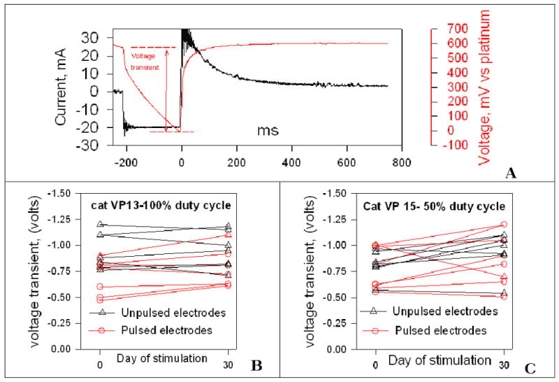
(A) 4 nC cathodic current stimulus pulse and the resulting voltage transient recorded from an implanted microelectrode. (B,C) The amplitude of the cathodic voltage transient from two cats, recorded before and after 30 days of stimulation for 8 hrs/day at 4 nC/phase. During the 30-day stimulation, a 100% duty cycle was used in cat VP13, while cat VP15 was stimulated with a 50% duty cycle.
During the 8 hours of daily stimulation, the cats were able to move about freely and they exhibited no adverse behavioral responses to the stimulation. To reduce problems related to electrostatic discharge, relative humidity within the enclosures was maintained above 55%. The electrodes selected for stimulation were pulsed in succession (“interleaved stimulation”). For a particular animal, the stimulus either was continuous for 8 hours (100% duty cycle), or 8 hours with 1second of stimulation, then 1 second without stimulation (50% duty cycle (1). In one animal stimulated with the 100% duty cycle, the stimulus amplitude was 10 μA (2 nC/phase), approximately the lowest threshold for the induction of visual percepts by intracortical microstimulation in a human subject (5). In 6 other cats, the stimulus amplitude was 4 nC/phase, which was at or above the threshold for induction of visual percepts by most of the microelectrodes implanted in the human patient. Three of theose cats were stimulated with a 100% duty cycle and 3 with a 50% duty cycle.
Data analysis
Twenty-four to 48 hours after the end of the last day of stimulation, the cats were deeply anesthetized with Phenobarbital and perfused through the ascending aorta with1 liter of Phosphate-buffered saline prewash followed by 3 liters of phosphate-buffered 4% formalin solution. After 24 hours the electrode array was withdrawn from the fixed brain and a block containing the tracks of the electrode shafts was embedded into paraffin. The tissue was sectioned perpendicular to the electrode shafts and photographed with a 1600×1200 dpi digital camera.
The paraffin sections that include the electrode sites were stained for GFAP, a marker for astrocytic processes, and for the neuronal marker NeuN. We have developed a double-staining procedure in which these markers are visualized in the same histologic section. The chromophore for the NeuN is Vector Red, yielding a reddish brown reaction product, and Vector nickel-DAB for the GFAP yielding a blue-gray product against the pale yellow background (Figure 3). In each of 3 adjacent 7-μm sections through the electrode tip site, the distance of the nucleolus of each neuron from the center of the electrode track was recorded using custom software. The distance of each neuron's nucleolus from the center of the electrode tips site was sorted to one of 5 concentric annuli, each 30 μm in width, surrounding the electrode tip site. The data set was analyzed with a 2-factor analysis of variances (fully randomized ANOVA model) in which the factors are (A) electrode site pulsed or not pulsed (2 levels) and (B), the radial distance from the center of the electrode track to the middle of each of the 30-micron annuli surrounding the track (5 levels). The independent variable is neuronal density within each annulus for each electrode (number of neurons in the annulus for that electrode / annulus area). Neuronal counts in each of the annuli were normalized on the annulus area in order to preserve homogeneity of variances across ANOVA cells, which is required for the analysis to be valid. The analysis was conducted using the ANOVA algorithm of GB-Stat (Dynamic Microsystems, Inc) which can handle differences in the number of entries (number of electrode sites) in different cells. Acceptable homogeneity of cell variances for the normalized data was confirmed using Bartlett's test. A significant Factor A indicates a difference in the density of neurons at the unpulsed vs. the pulsed electrode sites across all 5 annuli, within the 150 μm radius of measurement). A significant Factor B indicates a difference in the density of neurons as a function of distance from the center of the tip site. A significant A×B (cross-term) indicates an interaction between factors A and B, in essence signifying that the difference in neuronal density as a function of radial distance from the electrode (factor B) is dependent upon whether the electrode was or was not pulsed (factor A).
Figure 3.

Histologic sections through the tip sites (T) of unpulsed (A,C,E) and pulsed (B,D,F) microelectrodes from three cats in which the electrodes were pulsed with a 50% or 100% duty cycle, and with a pulse amplitude of 2 or 4 nC/phase. The microelectrodes had been implanted in cat VP 11 for 701 days, in VP15 for 1007 days and in VP16 for 348 days. Neuronal somas stained for NeuN are reddish-brown. Astrocyte processes stained for GFAP are black. Bar = 100 µm
Results
Figure 2B,C shows the amplitude of the cathodic voltage transient recorded from two cats, before and after 30 days of stimulation for 8 hrs/day at 4 nC/phase. These results are typical of those from the 6 cats stimulated for 8 hours/day for 30 days. During the 30-day stimulation, cat VP 13 was stimulated with the 100% duty cycle, while cat VP15 was stimulated with a 50% duty cycle. During the 30 day stimulation, the amplitude of the voltage transient of the pulsed electrodes tended to increase slightly, while those of the unpulsed electrodes exhibited no discernable trend. With few exceptions (e.g., one of the pulsed electrodes in cat VP15), the amplitude of the voltage transients changed by 20% or less.
Figure 3 shows histologic sections through the tips sites and perpendicular to the shaft of microelectrodes from arrays in which half of the electrodes were pulsed with the 100% or with the 50% duty cycle. The microelectrodes had been implanted in cat VP 11 for 701 days, in VP15 for 1007 days and in VP16 for 348 days. The profile of the electrode track, about 30 μm above the tip (“-T-“), is shown. The red-brown neurons, the fibrous astrocytes, the astrocytic fibers around the electrode track, and the astrocytic end-feet around blood vessel are visible. In all cases, there was some enhanced GFAP reaction surrounding the unpulsed tip sites (Figure 3 A,C,E). This response was greater around the tips of microelectrodes pulsed for 30 days with either the 50% or the 100% protocols and at 4 nC/phase, (Figure 3 D,F), indicating a reactive astrocytosis in response to the prolonged stimulation, in addition to an increased loss of viable neurons close to the tip sites. There are few NeuN-stained (and presumably viable) neurons within the region of reactive astrocytosis.
Figure 4 shows the histogram of neuronal density vs. distance from the electrode tips site for cat VP11, in which 8 of the microelectrodes were pulsed continuously (100% duty cycle) for 8 house per days for 30 days. The stimulation was begun 910 days after implanting the array. The neuronal density within each 30 μm annulus is essentially identical for the pulsed and unpulsed electrodes, even within 60 μm of the tip site, and Factor A of the ANOVA was not significant (p=0.66), indicating no significant effect of the stimulation on neuronal density. As suggested by inspection of the histogram, the cross-factor effect, A×B, is not significant (p = 0.81)
Figure 4.

Distance-neuronal density histogram for a cat in which 8 electrodes were pulsed for 8 hours/day for 30 days at 50 pps, continuous (100% duty cycle). The stimulus amplitude was 2 nC/phase. The error bars are the standard deviations of the neuronal counts in each annulus, for the 8 electrode tip sites in each group. The neuronal density surrounding the pulsed and unpulsed electrodes was not significantly different (p=.0.61, from the 2-factor ANOVA)
Figure 5 show the histograms of neuronal density vs. distance for the pulsed and unpulsed electrodes sites from 6 cats in which approximately half of the electrodes were pulsed for 8 hours/day for 30 days at 50 pps (Six of the pulsed electrodes were withdrawn from the study when the cathodic voltage transient exceeded the stimulator compliance voltage.) The stimulus amplitude was 4 nC/phase (20 μA with a pulse duration of 200 μA). The geometric charge density was approximately 200 μC/cm2. Figure 5A is the composite histogram for the 3 cats in which the stimulus amplitude was 4 nC/phase and the duty cycle was 100%, and Figure 5E is the composite for the 3 cats in which the duty cycle was 50% (1 sec with stimulation, 1 sec without stimulation).
Figure 5.
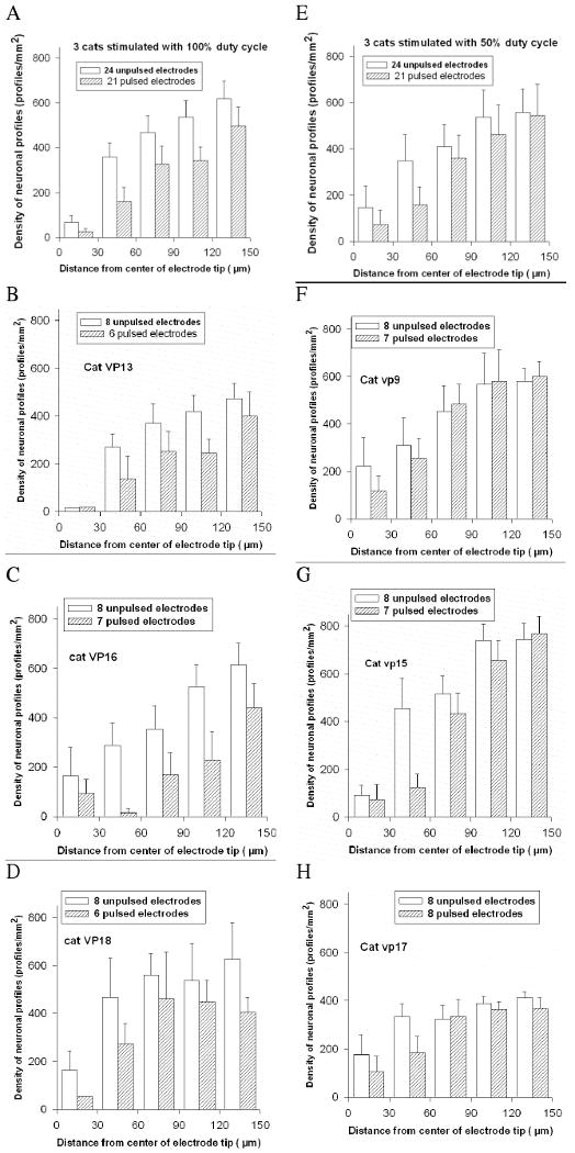
Left column (A)-Histogram of neuronal density vs. distance from the electrode tips sites for 3 cats in which the electrodes were pulsed continuously (100% duty cycle) for 8 hr/day for 30 days at 4 nC/phase and 50 Hz. (B,C,D) the distance-density histograms for the individual cats stimulated with the 100% duty cycle. For the three cats, the neuronal density surrounding the pulsed and unpulsed electrodes was significantly different (p < .001, from the 2-factor ANOVA) Right Column:(E) Distance-density histogram for the electrode tips sites from 3 cats in which the electrodes were pulsed with a 50% duty cycle for 8 hr/day for 30 days, also at 4 nC/phase. (F,G,H) Distance-density histograms for the individual cats stimulated with the 50% duty cycle. The error bars are the standard deviations of the neuronal counts in each annulus, for the electrode tip sites in each group. For the three cats, the neuronal density surrounding the pulsed and unpulsed electrodes was significantly different (p =.021, from the 2-factor ANOVA)
For each of the 7 cats (Figure 4 and Figure 5), Factor B of the ANOVA is highly significant (p < .0001) indicating a significant difference in neuronal density as a function of radial distance from the center of the electrode tip sites. This is evident by just by inspection of the distance-density histograms. Presumably, the loss of neurons around the tips of the unpulsed electrodes is due to mechanical injury arising from insertion and long-term residence of the intraparenchymal electrodes. For the group of 3 cats in which the electrodes were pulsed with a 100% duty cycle, Factor A of the ANOVA is highly significant (p < .0001), indicating a marked difference (reduction) in the neuronal density surrounding the pulsed vs. the unpulsed electrodes. However, the cross-term A×B is not significant (p = 0.6), indicating that the difference in neuronal density vs. distance from the electrode is similar for the pulsed and unpulsed electrodes, within the 150 μm radius of measurement. Stated differently, the neuronal loss due to the stimulation extends beyond the 150 μm radius of measurement.
For the group of 3 cats in which the electrodes were pulsed with a 50% duty cycle, Factor A of the ANOVA is significant (p =.021), indicating a small but significant difference (reduction) in the neuronal density surrounding the pulsed vs. the unpulsed electrodes. However, the cross-term A×B also is significant (p = .045), indicating that the reduction in neuronal density due to the stimulation is dependent upon radial distance from the center of the tip site. In the distance-density histogram for the 3 animals stimulated with the 50% duty cycle group (Figure 5E), the difference in neuronal density around the pulsed and unpulsed electrode sites is greatest in the innermost 2 annuli (within 60 μm of the center of the electrode track). A post-hoc comparison (unpaired 2-sided t-test) of the neuronal density in the innermost annulus around the pulsed and unpulsed electrodes was not significant (p= 0.47), probably because of the small number of neurons within 30 μm of the electrode tips, which would render the test underpowered. However, the post-hoc test for the second (30 to 60 μm) annulus was significant (p = 0.015 after the Bonferroni correction for 5 comparisons). For each of the outer 3 annuli, between 60 and 150 μm from the electrode tips, the post-hoc comparisons of neuronal density around the pulses and unpulsed electrodes were not significant (p > 0.5, both with and without the Bonferroni correction for 5 comparisons).
Discussion
We found that for microelectrodes implanted chronically in cats' sensorimotor cortex, continuous stimulation for 8 hours per day for 30 days at 2 nC/phase and with a geometric charge density of 100 μC/cm2 at 50 Hz (Figure 3) produced no detectable change in neuronal density in the tissue surrounding the microelectrode tips. However, we also found that continuous (100% duty cycle) electrical stimulation for 8 hours per day for 30 days at 4 nC/ph, and at a geometric charge density of 200 μC/cm2 and at a pulse repetition rate of 50 Hz, there was a loss of neurons over a radius of at least 150 μm from the microelectrode (Figure 5). This is equal to, or greater than the radius over which there is neuronal loss around the unpulsed electrodes. In any sensory neuroprosthesis, the amplitude of the electrical stimulation delivered through any particular electrode would be time-variable and the protocol employing the 50% duty cycle was intended to approximate this reality. In the animals stimulated with the 50% duty cycle (1 sec of stimulation alternating with 1 sec without stimulation), the electrical stimulation also induced some neuronal loss within 60 μm of the center of the electrode tracks, in addition to the neuronal loss that is unrelated to the electrical stimulation. However, with the 50% duty cycle, the latter mechanism was responsible for most of the neuronal loss within 150 μm of the electrode tip. The 50% duty cycle is not intended to represent the temporal pattern of stimulation that would be used in a functioning visual prosthesis. It does, however, illustrate the influence of modulating the stimulus amplitude on the extent of the tissue injury that may occur during prolonged intracortical microstimulation. In a functional cortical level visual prosthesis, the stimulation would be modulated since continuous stimulation conveys no information, and in fact, Schmidt et al. (5) noted that phosphenes faded rapidly when the intracortical stimulation was prolonged. In a functioning visual prosthesis, it should be possible to include a provision that no individual electrode would be active more than 50% of the time
In the present study, in which the microstimulation was applied for 8 hrs per day on 30 successive days at 50 pps, the threshold for stimulation-induced tissue injury lay between 2 and 4 nC/ph and a charge density of 100-200 μC/cm2. This is similar to the threshold of tissue injury (approximately 3 nC/phase) induced by microstimulation in the cat cochlear nucleus using activated iridium microelectrode with the same active surface areas as those used in the present study, but in which the stimulation was delivered at a much higher rate (500 pps) and for a total of only 7 hours (McCreery et al. 1994). In that study, the threshold for neural injury was strongly correlated with stimulus charge per phase. This concordance of the neuronal injury thresholds in the two studies does suggest that a common mechanism may be responsible for the stimulation-induced neuronal injury in these quite different neuronal substrates.
The distance (d) over which a stimulus pulse of amplitude (I) is able to evoke an action potential in a neuron is determined by the neuron's current- distance constant (k) where d=(I/k)1/2. In several studies, the values of k for the cell bodies and axons of cerebral cortex neurons was found to range from 250 to 3,500 μA/mm2 for a stimulus pulse duration of 200 μs (2). Thus a 20 μA, 200 μs stimulus pulse (the parameters used in the present study) should activate neurons with low excitability (k = 3,500 μA/mm2) within 75 μm of the electrode and should activate neurons with high excitability (k = 250 μA/mm2) within a radius of approximately 280 μm. We detected a significant loss of neurons within 60 μm of the electrodes pulsed for 30 days (240 hours) with a 50% duty cycle. In the case of a visual prosthesis implemented by intracortical microstimulation, if the vulnerability of the neurons of the human visual cortex to injury by prolonged pulsatile stimulation is similar to that of neurons in the cat sensorimotor cortex having similar excitability, we would expect some stimulation-induced loss of neurons within about 60 μm of electrodes pulsed with the parameters used in the present study, and we would expect that this neuronal loss would engender at least some compression of the relation between stimulus pulse amplitude and the thresholds and intensity of the elicited visual percepts. The magnitude of this compression would depend upon the neurons' current- distance constant and also upon the size and spatial distribution of the neuronal population that must be activated in order to produce the percepts. Thus, if a large number of low-threshold neurons within a relatively large volume of cortex must be excited in order to evoke the visual percept, the loss of neurons within 60 μm of the electrode probably would be relatively inconsequential. Conversely, if the percept is elicited by activating a small number of neurons with very high threshold (and which therefore must be very close to the electrode in order to be activated) then the consequences of the loss of these neurons on perceptual threshold and recruitment would be greater. There also is the issue of whether the excitability (threshold) of these neurons would remain stable over time. The excitability of the cortical neurons was not measured in the present study, but in an earlier study (9), we found that a stimulus regimen in which all 16 intracortical electrodes were pulsed for 7 hours in the interleaved mode at 20 μA, 200 μs/ph and at 50 Hz, the threshold for neural excitation increased by an average of about 30% during the 7 hours of stimulation. However, the same study also demonstrated that this stimulation-induced depression of neuronal excitability could be minimized by a stimulus protocol in which the intrinsic spatial resolution of an array of penetrating microelectrodes is used to maximum advantage; namely, sequential pulsing at amplitudes for which there is minimum overlap of the effective stimulus from adjacent electrodes.
Six of the 48 pulsed microelectrodes were deleted from the study because, at some point during the 30 days of stimulation, their voltage transient reached the stimulator's compliance limit of -0.6 volts vs. the platinum counter electrode. The criterion of a total cathodic voltage excursion of -0.6 volts vs. the platinum counter electrodes was adopted to minimize the likelihood that the electrode-electrolyte interface might reach a potential at which electrolysis of water could occur. It should be regarded as extremely conservative, since undoubtedly part of the voltage excursion can be attributed to “access voltage, “ which is generally attributed to the voltage drop across resistive medial surrounding the electrode, whereas the electrochemical potential that drive the various charge injection processes at the electrode-electrolyte interface is determined only by the portion of the voltage excursion that correspond to polarization of the interface (24). While this simplified view of the “access voltage” is debatable, certainly some portion of the total voltage excursion does not contribute to the polarization of the electrode-tissue interface. In any chronic stimulation protocol, some additional access voltage drop, beyond the -0.6V can be tolerated without concern for the integrity of the electrode-tissue interface. Therefore it would be expected that in a chronically implanted neural prosthesis, electrode cathodic voltage excursions could safety exceed -0.6V. However, in this study we used the more conservative rule of limiting the total cathodic voltage excursion to -0.6V in order to separate the effects of electrochemical effects from those of biological effects. Since our findings demonstrate neuronal loss, despite our conservative method of voltage excursion limitation, this suggests that mechanisms other than irreversible electrochemical processes at the electrode-tissue interface are responsible. It is noteworthy that about 12% of the anodically-biased activated iridium microelectrodes reached the compliance limit, despite the relatively low stimulus amplitude (4 nC per pulse, and a geometric charge density of approximately 200 μC/cm2). Whether this indicates a possible charge injection limitation for our present electrode design is unclear. Pending development of electrode materials that have a significantly greater charge injection capacity, our results suggest the merits of using intracortical stimulation electrodes with surface areas at least as great, or possibly greater than the 2,000 μm2 used in this study.
The study's findings raise several questions whose resolution must await future studies, perhaps the most germane being whether the distribution of the neuronal loss around the electrodes pulsed with the 50% duty cycle would come to resemble that surrounding the electrode pulsed with the 100% duty cycle if the duration of the stimulus regimen was extended beyond 30 days. More generally, does the situation depicted in Figures 4 and 5 after 30 days (240 hours) of stimulation represents a steady-state condition or would additional neuronal loss occur in the ensuring weeks and months?
During long-term implantation, the microelectrode arrays become encased within a capsule of loose connective tissue, and they also tend to indent the surface of the cerebral cortex. However, we have been able to record resolved neuronal action potentials from the intracortical microelectrodes for more than 1,000 days (19, 20), which suggests that the neurons beneath the array remain viable for an extended period of time. We can be reasonably confident that the loss of neurons around the unpulsed electrodes does represent a steady state condition, since the electrodes were implanted for 348 to 1,282 days prior to the start of the stimulation. However, the amount of neuronal loss around the tips of unpulsed electrodes does demonstrate the need for improved electrode designs and improved methods of inserting the electrodes. The formation of a glia capsule with accompanying loss of neurons close to the microelectrodes has been observed with virtually all types of penetrating microelectrodes and in a large number of species (25-29). There is good evidence that the tissue injury and neuronal loss derives from both the trauma of inserting the electrodes and also from their continued residence within the brain. The latter might be mitigated by controlling the sub-acute phase of the inflammatory response induced by the electrodes (27, 30-32)}. Tissue injury might also be mitigated by a judicious change in the physical configuration of the electrodes and /or by modifying the physical properties of the electrode array surface, including appropriate modifications to the shanks' tip region and fabrication of the shanks from other materials such as nanoporous silicon (25, 33, 34)
Acknowledgments
We thank Dr. Panya Manoonkitwongsa, Mr. Clarence Graham and Mr. Jesus Chavez for preparation of the histologic material, Mr. David Minik, Mr. Aloysius Kowalewski and Ms. Victoria Cheng for fabricating the microelectrode arrays, and Mr. Leo Bullara for assistance with the design of the arrays. Mr. Kowalewski also assisted with the 30-day stimulation procedures. Mrs. Yelana Smirnova and Nijole Kuleviciute performed the computerized image analysis of the histologic sections. The animal studies were approved by the Animal Care & Use Committee of HMRI, and were performed under the guidelines set forth in the Guide to Care and Use of Laboratory Animals (1996 edition). Mrs. Edna Smith managed and assisted with the animal surgeries, and we thank Mrs. Smith and her animal care staff for excellent care of the animals.
This work was funded by a Bioengineering Research Partnership grant from the National Institutes of Health (R01-NS40690-01) and by the Huntington Medical Research Institutes.
Footnotes
Author's Contributions: Drs. Douglas McCreery and Philip Troyk designed the study and wrote the manuscript. Dr. McCreery conducted all phases of the animal studies, and performed the data analysis. Dr. Troyk designed the compliance-limited stimulators used in the animal studies. Dr. Victor Pikov wrote the image analysis software used to determine the neuronal density vs. distance from the stimulating microelectrode sites.
Competing Interests: The authors have no personal or financial interests that would influence the interpretation of the data or the presentation of the information. This work was funded by a Bioengineering Research Partnership grant from the National Institutes of Health (R01-NS40690-01) and by the Huntington Medical Research Institutes.
References
- 1.Jankowska E, Padel Y, Tanaka R. The mode of activation of pyramidal tract cells by intracortical stimuli. J Physiol. 1975;249:617–636. doi: 10.1113/jphysiol.1975.sp011034. [DOI] [PMC free article] [PubMed] [Google Scholar]
- 2.Tehovnik EJ. Electrical stimulation of neural tissue to evoke behavioral responses. J Neurosci Methods. 1996;65:1–17. doi: 10.1016/0165-0270(95)00131-x. [DOI] [PubMed] [Google Scholar]
- 3.McCreery DB, Han M, Pickov V. Comparison of the electrophysiologic responses evoked in the inferior colliculus of the cat by surface macroelectrodes and penetrating microelectrode implanted in the cochlea nucleus. Conference on Implantable auditory prostheses; Lake Tahoe, CA. 2009. [Google Scholar]
- 4.Bak M, Girvin JP, Hambrecht FT, Kufta CV, Loeb GE, Schmidt EM. Visual sensations produced by intracortical microstimulation of the human occipital cortex. Med Biol Eng Comput. 1990;28:257–259. doi: 10.1007/BF02442682. [DOI] [PubMed] [Google Scholar]
- 5.Schmidt EM, Bak MJ, Hambrecht FT, Kufta CV, O'Rourke DK, Vallabhanath P. Feasibility of a visual prosthesis for the blind based on intracortical microstimulation of the visual cortex. Brain. 1996;119(Pt 2):507–522. doi: 10.1093/brain/119.2.507. [DOI] [PubMed] [Google Scholar]
- 6.Veraart C, Duret F, Brelen M, Oozeer M, Delbeke J. Vision rehabilitation in the case of blindness. Expert Rev Med Devices. 2004;1:139–153. doi: 10.1586/17434440.1.1.139. [DOI] [PubMed] [Google Scholar]
- 7.Cohen ED. Prosthetic interfaces with the visual system: biological issues. J Neural Eng. 2007;4:R14–31. doi: 10.1088/1741-2560/4/2/R02. [DOI] [PubMed] [Google Scholar]
- 8.McCreery D. Tissue reaction to electrodes: The problem of safe and effective stimulation of neural tissue. In: Horch KW, Dhillon GS, editors. Neural Prosthesis: Theory and Practice. World Scientific Publishing; River Edge, NJ: 2004. pp. 592–607. [Google Scholar]
- 9.McCreery DB, Agnew WF, Bullara LA. The effects of prolonged intracortical microstimulation on the excitability of pyramidal tract neurons in the cat. Ann Biomed Eng. 2002;30:107–119. doi: 10.1114/1.1430748. [DOI] [PubMed] [Google Scholar]
- 10.McCreery DB, Agnew WF, Yuen TG, Bullara L. Charge density and charge per phase as cofactors in neural injury induced by electrical stimulation. IEEE Trans Biomed Eng. 1990;37:996–1001. doi: 10.1109/10.102812. [DOI] [PubMed] [Google Scholar]
- 11.McCreery DB, Agnew WF, Yuen TG, Bullara LA. Relationship between stimulus amplitude, stimulus frequency and neural damage during electrical stimulation of sciatic nerve of cat. Med Biol Eng Comput. 1995;33:426–429. doi: 10.1007/BF02510526. [DOI] [PubMed] [Google Scholar]
- 12.McCreery DB, Yuen TG, Agnew WF, Bullara LA. Stimulation with chronically implanted microelectrodes in the cochlear nucleus of the cat: histologic and physiologic effects. Hear Res. 1992;62:42–56. doi: 10.1016/0378-5955(92)90201-w. [DOI] [PubMed] [Google Scholar]
- 13.McCreery DB, Yuen TG, Agnew WF, Bullara LA. Stimulus parameters affecting tissue injury during microstimulation in the cochlear nucleus of the cat. Hear Res. 1994;77:105–115. doi: 10.1016/0378-5955(94)90258-5. [DOI] [PubMed] [Google Scholar]
- 14.Carmena JM, Lebedev MA, Crist RE, O'Doherty JE, Santucci DM, Dimitrov DF, Patil PG, Henriquez CS, Nicolelis MA. Learning to control a brain-machine interface for reaching and grasping by primates. PLoS Biol. 2003;1:E42. doi: 10.1371/journal.pbio.0000042. [DOI] [PMC free article] [PubMed] [Google Scholar]
- 15.Lebedev MA, Nicolelis MA. Brain-machine interfaces: past, present and future. Trends Neurosci. 2006;29:536–546. doi: 10.1016/j.tins.2006.07.004. [DOI] [PubMed] [Google Scholar]
- 16.Bradley DC, Troyk PR, Berg JA, Bak M, Cogan S, Erickson R, Kufta C, Mascaro M, McCreery D, Schmidt EM, Towle VL, Xu H. Visuotopic mapping through a multichannel stimulating implant in primate V1. J Neurophysiol. 2005;93:1659–1670. doi: 10.1152/jn.01213.2003. [DOI] [PubMed] [Google Scholar]
- 17.Troyk P, Bak M, Berg J, Bradley D, Cogan S, Erickson R, Kufta C, McCreery D, Schmidt E, Towle V. A model for intracortical visual prosthesis research. Artif Organs. 2003;27:1005–1015. doi: 10.1046/j.1525-1594.2003.07308.x. [DOI] [PubMed] [Google Scholar]
- 18.Troyk PR, Bradley D, Bak M, Cogan S, Erickson R, Hu Z, Kufta C, McCreery D, Schmidt E, Sung S, Towle V. Intracortical visual prosthesis research - approach and progress. Conf Proc IEEE Eng Med Biol Soc. 2005;7:7376–7379. doi: 10.1109/IEMBS.2005.1616216. [DOI] [PubMed] [Google Scholar]
- 19.Liu X, McCreery DB, Bullara LA, Agnew WF. Evaluation of the stability of intracortical microelectrode arrays. IEEE Trans Neural Syst Rehabil Eng. 2006;14:91–100. doi: 10.1109/TNSRE.2006.870495. [DOI] [PubMed] [Google Scholar]
- 20.Liu X, McCreery DB, Carter RR, Bullara LA, Yuen TG, Agnew WF. Stability of the interface between neural tissue and chronically implanted intracortical microelectrodes. IEEE Trans Rehabil Eng. 1999;7:315–326. doi: 10.1109/86.788468. [DOI] [PubMed] [Google Scholar]
- 21.Robblee LS, Lefko J, Brummer SB. Activated Ir: An electrode suitable for reversible charge injection in saline solution. Journal of the Electrochemical Society. 1983;130:731–733. [Google Scholar]
- 22.Cogan SF, Troyk PR, Ehrlich J, Plante TD, Detlefsen DE. Potential-biased, asymmetric waveforms for charge-injection with activated iridium oxide (AIROF) neural stimulation electrodes. IEEE Trans Biomed Eng. 2006;53:327–332. doi: 10.1109/TBME.2005.862572. [DOI] [PubMed] [Google Scholar]
- 23.Troyk PR, Detlefsen DE, DeMichele GAD. A multifunctional neural electrode stimulation ASIC using NeuroTalk interface. Engineering in Medicine and Biology Society, 28th annual meeting; 2006. pp. 2944–2997. [DOI] [PubMed] [Google Scholar]
- 24.Cogan SF. Neural stimulation and recording electrodes. Annu Rev Biomed Eng. 2008;10:275–309. doi: 10.1146/annurev.bioeng.10.061807.160518. [DOI] [PubMed] [Google Scholar]
- 25.Edell DJ, Toi VV, McNeil VM, Clark LD. Factors influencing the biocompatibility of insertable silicon microshafts in cerebral cortex. IEEE Trans Biomed Eng. 1992;39:635–643. doi: 10.1109/10.141202. [DOI] [PubMed] [Google Scholar]
- 26.Turner JN, Shain W, Szarowski DH, Andersen M, Martins S, Isaacson M, Craighead H. Cerebral astrocyte response to micromachined silicon implants. Exp Neurol. 1999;156:33–49. doi: 10.1006/exnr.1998.6983. [DOI] [PubMed] [Google Scholar]
- 27.Shain W, Spataro L, Dilgen J, Haverstick K, Retterer S, Isaacson M, Saltzman M, Turner JN. Controlling cellular reactive responses around neural prosthetic devices using peripheral and local intervention strategies. IEEE Trans Neural Syst Rehabil Eng. 2003;11:186–188. doi: 10.1109/TNSRE.2003.814800. [DOI] [PubMed] [Google Scholar]
- 28.Szarowski DH, Andersen MD, Retterer S, Spence AJ, Isaacson M, Craighead HG, Turner JN, Shain W. Brain responses to micro-machined silicon devices. Brain Res. 2003;983:23–35. doi: 10.1016/s0006-8993(03)03023-3. [DOI] [PubMed] [Google Scholar]
- 29.Griffith RW, Humphrey DR. Long-term gliosis around chronically implanted platinum electrodes in the Rhesus macaque motor cortex. Neurosci Lett. 2006;406:81–86. doi: 10.1016/j.neulet.2006.07.018. [DOI] [PubMed] [Google Scholar]
- 30.Spataro L, Dilgen J, Retterer S, Spence AJ, Isaacson M, Turner JN, Shain W. Dexamethasone treatment reduces astroglia responses to inserted neuroprosthetic devices in rat neocortex. Exp Neurol. 2005;194:289–300. doi: 10.1016/j.expneurol.2004.08.037. [DOI] [PubMed] [Google Scholar]
- 31.Polikov VS, Tresco PA, Reichert WM. Response of brain tissue to chronically implanted neural electrodes. J Neurosci Methods. 2005;148:1–18. doi: 10.1016/j.jneumeth.2005.08.015. [DOI] [PubMed] [Google Scholar]
- 32.Zhong Y, Bellamkonda RV. Dexamethasone-coated neural probes elicit attenuated inflammatory response and neuronal loss compared to uncoated neural probes. Brain Res. 2007;1148:15–27. doi: 10.1016/j.brainres.2007.02.024. [DOI] [PMC free article] [PubMed] [Google Scholar]
- 33.He W, McConnell GC, Bellamkonda RV. Nanoscale laminin coating modulates cortical scarring response around implanted silicon microelectrode arrays. J Neural Eng. 2006;3:316–326. doi: 10.1088/1741-2560/3/4/009. [DOI] [PubMed] [Google Scholar]
- 34.Moxon KA, Hallman S, Aslani A, Kalkhoran NM, Lelkes PI. Bioactive properties of nanostructured porous silicon for enhancing electrode to neuron interfaces. J Biomater Sci Polym Ed. 2007;18:1263–1281. doi: 10.1163/156856207782177882. [DOI] [PubMed] [Google Scholar]